Thank you , i am new with the foc mode which i will run this year… Didn’t think about this amp"pics" of the motor…
As i was thinking to get the power used by the motor close to the power of the battery in order to stay around a nice torque/trust area ( bigger propeller data will be interesting  )
)
Missing the rpm value on the data for calculating the torque value …
I am trying to get my way around the numbers in order to estimated the best combo pitch/diameter/rpm for my needs
The metr.at tool is just incredible. Therefore, a few questions
1 - Is there another tool on the market that aggregates speed with the real time consumption data (Voltage, current (battery)
2 - can we get instantaneous consumption in WH not averaged (smoothed) on a distance we don’t really know how it has been calculated ? My guestimate would be that the speed is calculated from the derivative of the distance travelled over the last 1 or 2 seconds (from GPS data) which would mean it is the quasi real time speed and consumption which would be a gift.
To compare prop efficiency, we could create a set of indicators:
I propose this first one:
SPUP : Speed Per Unit of Power: kmph reached per consumed power unit (or WH)
= speed (kph) / [ Voltage (V) x Current (Amp)]
Conditions: at identical duty cycles (DC) (could be linearised by a rule of threes even if I am not sure a motor reacts in a linear way)
That’s where the Maytech remote is helpful: 33% DC, 66% DC…
If it is demonstrated that the motor power and Duty Cycle are proportional therefore linear, I propose the SPUP-L
SPUP-L : Linearised Speed Per Unit of Power: kmph reached per consumed power unit (or WH) at any duty cycle.
= speed (kph) x Duty Cycle (%) / [ Voltage (V) x Current (Amp)]
Conditions: none = at any duty cycles (DC)
Xmatic app is worth the try , more worried about the fw update for the new vesc 75/300…
I have set my remote with 2 modes 80 and 100% , will see i just need to finish my board …
1 Like
Lets have further discussion about metr app here:
Hello,
I found this Esc do you think I can achieve with better cooling the promised 200A continuous?
I think It looks quite good, but I can’t see the big capatitors.
https://m.banggood.com/de/HGLRC-Flipsky-High-Current-FSESC-200A-60V-ESC-base-on-VESC6-for-Electric-Skateboard-Rc-Model-p-1476019.html?gmcCountry=DE¤cy=EUR&cur_warehouse=CN&createTmp=1&ID=31476135017&utm_source=googleshopping&utm_medium=cpc_bgs&utm_content=frank&utm_campaign=pla-ods-de&gclid=Cj0KCQjwrdjnBRDXARIsAEcE5YnCXWmbOpUDaZjm1EonXH1lv5ycUykUXnpuMUN1sH5oRM7uEDL9cpMaAsPOEALw_wcB
Max
Very nice. Curr:Currently being tested by @Jasey with 80100 and/or 6384PG outrunner motor(s).
Your link for desktop users (non mobile) and in English New 200A Vesc based Flipsky ESC 225€ at Banggood
So today i drove again with 8" pitch. And it was a hard game. I returned to the pier and other places on land 6 or more times to figure out what was recorded by the metr app and adapted the values by it as well.
I activated High current sampling mode and Sample in V0 and V7
I set Current filter constant to 0
Motor current 110A
Battery current 100A
Control Type Duty Cycle no reverse
I think the current filter was the most important thing.
I still had once ABS HW Overcurrent in the beginning, i think i should also increase the Positive Ramping Time.
I forgot to mention the Stator Saturation Compensation i set to 0.1 , could be also important.
So this is the result:
If you have further suggestions how i can increase the performance of the VESC please let me know.
This is recorded using a large windsurfboard without any wing. It has of cause much higher power demand than any Efoil. As you can see, the 6384PG and Nicks VESC can hold the power up for a long time at a high duty cycle. The metr saved my day, because you can adapt every parameter the VESC Tool shows directly via the app in your smart phone.
1 Like
Activating v0 v7 to double the frequency ?
Measuring current in V0 and V7 means: There are 3 sets of switches, and VESC tags each state the 3 switches can have as V0-V7. V0 is all OFF, V7 is all ON. VESC FOC uses bipolar mode switching, so the switches are all V0 (OFF) once per switching cycle, at the switching frequency. This is when vesc 4 measures freewheeling current through the low side switches. But if you have phase shunts, you can also measure current when all the switches are ON, this is period V7. Measuring current in V0 and V7 means you measure current 2x per switching cycle, which is 2x the control frequency. More data means better control.
Ok , i am still in testing mode Foc , just 5% gain in amp using high frequency 30 instead 15 for my 3 poles motor , v0 v1 didn’t change anything but i did not understood that was just for sampling …
I swapped the 0.5mOhm shunts by 0.3mOhm now. Additionally i added 3x 1.2mF UHW1J122MHD capacitors directly on the current rails.
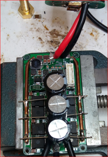
These current rails are copper wire with 3.25mm diameter , AWG8
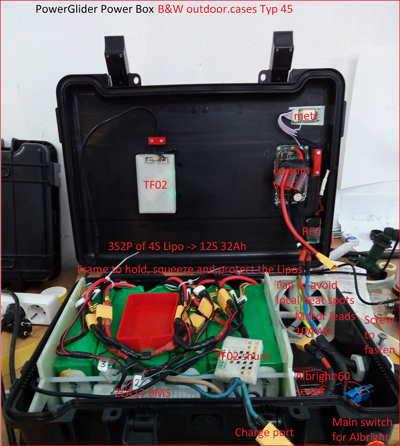
I would like to add battery cables to the middle of the current rail, additionally to the ones you see on the picture in parallel and solder them all together into the XT90 plug going to the relais. That would be two times AWG10 then. I found my battery has inner resistance of 27mOhm by the measured voltage sag from metr VESC data. I will also use no shunt for the battery gauge any more but rely on VESC data recording to my mobile which i mount on my box. The rest of the battery cabling i will redo with 10mm^2. On the motor side i will continue with AWG10, a 3 phase cable sold to me as 3x6mm^2 ,hahaha.
If you have more advice, please let me know.
Nick, could you compile a new FW for the 0.3mOhm shunts for me please?
There is not much power missing, maybe 10% more would be a pleasure, and no more HW ABS OC.
Just ran the motor detection:
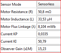
you can find the corresponding pic for the 0.5mOhm in this thread at 3. April 2019 .
So the new shunts might have even little less the 0.3mOhm or the old shunts had little more than 0.5mOhm.
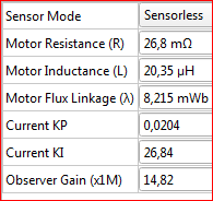
Thanks for the updated FW! Now it shows correct values again:


How much Heat power can take a outrunner watercooled : 200-250w ?
Lets see
Vesc always shows the resistance of one phase in a Wye configuration, thats 27mOhms. But this is not the resistance of the motor alone, i have cables and plugs and connections. I use 3 phase cable with the above mentioned AWG10 with a length of 2,7m, that makes 9-10mOhms per phase.
So we get 17mOhms for each motorphase. This fits also my initial testing with old Vesc4 with short leads.
I have a (hopefully sinus) peak current of 110A tested for 14 minutes.
I would estimate the ohmic losses by 110/sqrt(2), which makes 77A RMS, square this and multiply with 34mOhm, so 205W ohmic losses. Please correct me if this approach is wrong or too simple.
There are other losses of cause, like hysteresis of iron and so forth, but they might not contribute to the hot spot of the winding temperature, because they are cooled by the water at the stator. Same goes for the friction losses. So overall losses at full speed full load i would estimate 400-500W.
Here we got the new data for the 300µohm shunts.
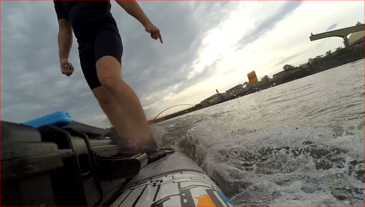
Perfect performance. 95% dutycycle all the time. But the rest of my system is at its limits. Some PLA parts inside battery box are deformed now, especially around the motor cables and connectors. It was a good idea to make a pause in the middle of my trip to Frankfurt downtown.
In the end, after opening the box, the cables were hotter than the batteries.
Its so much fun, there were a lot of waves, i overtook a freighter and i did not fall! The third day in order!
2 Likes
Is this hydro-foiling or an e-surfboard?
This is to power an electric surfboard, but it can be used for any stuff, where you have a battery and a motor or other stuff to power. It can power a BLDC, a DC Motor, another converter, a heater.
The data above shows a continuous load for the new developed Vesc with some practical background.
Like you have a windsurfing with a nice breeze and good sail. And you can maneuvre where ever you want.
I will make more attempts.
Of course! The more things it gets tested on the better. I want you to break it so I can fix the weakest point
I suspect the weakest point on my new design is the capacitor board. I should have made a 6 layer capacitor board instead of a 2 layer board.
Sorry, i do not want to break it! ![]()
The capacitor board is indeed a weak point, one of the caps dissoldered under mechanical stress. That happened before i added the 3x1.2mF to the board directly, and it was my motivation. Tomorrow i will get some new plugs and hopefully also leads to enhance the input section. I also would like to protect the caps against overheating, so i would like to put an NTC to them. Which type do i need?
Some people ask me if its fun to drive with 18-22kmph speed. I have this conclusion at the moment:
In the beginning: Sure, you need to train to drive curves and find your course and estimate the velocity of others.
After learning: If you have calm water, no, it is not challenging anymore. Now you should try waves or choppy water. There you always find challenges, even on the river Main. Its hard to maintain full control and the reaction must be quick not to fall. Yes, that is sporty and its fun.
I tested a new capacitor board sample today with DC current. 2 layer board, 1oz copper, 3x 1200uF nichicon capacitors, with 8awg wire in and out, and a little dab of solder between in and out to help conduction.
It looks like 90A is ok for continuous use, though things do get hot. 125A is ok for a minute or two. At 125A, even the 8awg wires get over 100C after a minute. That’s just going to be a hard limit for the wire size and this class of motor controller. Higher than 125A input can’t be maintained without upgrading EVERYTHING: batteries, cables, heat sink, all of it.
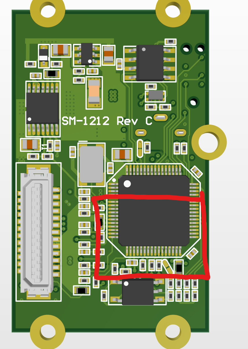
If you want to add an external temp, you’ll likely need a fine soldering tip and a microscope. I didn’t include any of the pieces on the layout so it’s an all jumper wire task. It’s on the bottom side of the logic board also, so…
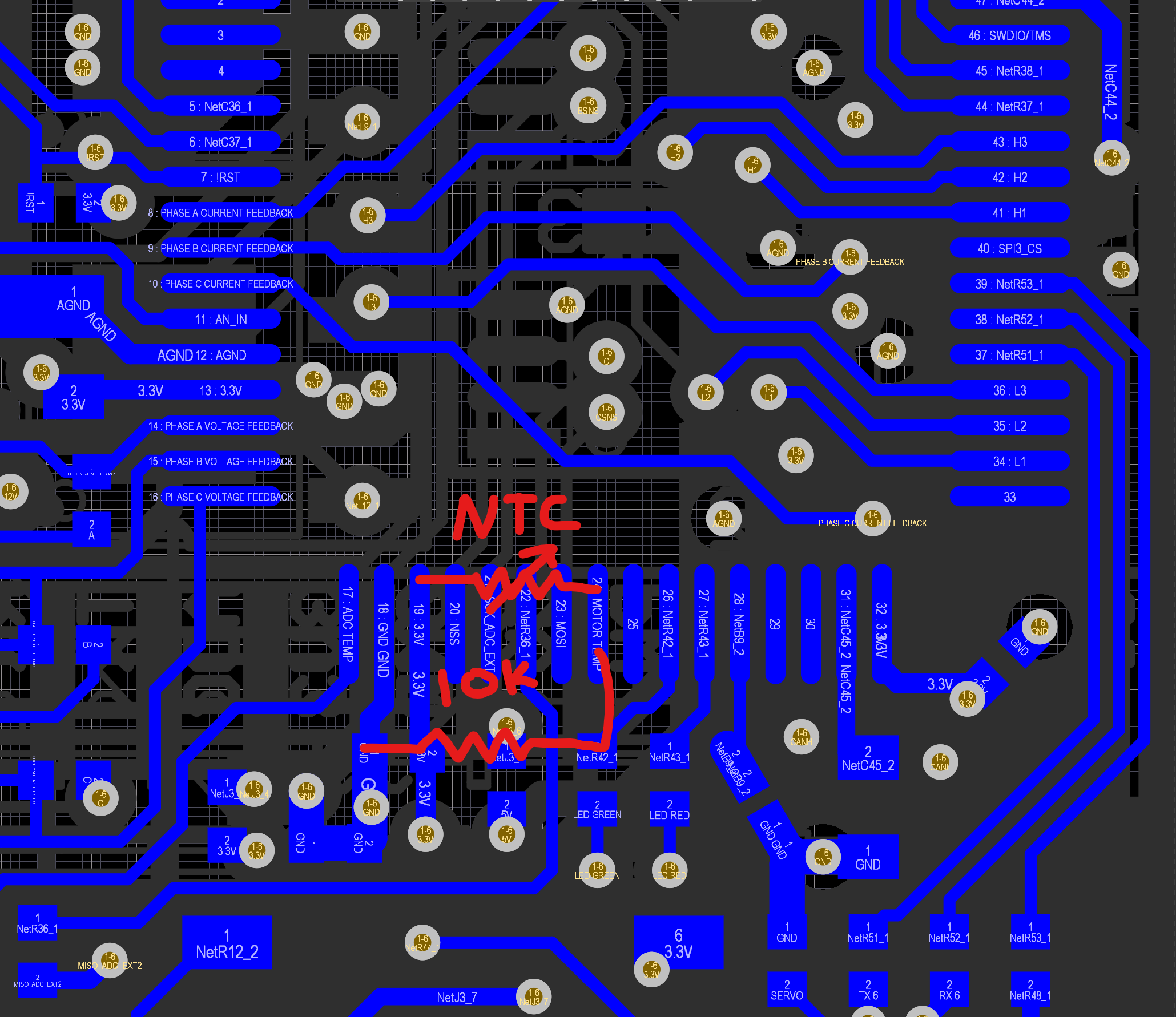
For the divider, you will need a 10k resistor from motor temp input to ground, and an NTC thermister like murata NXRT15XH103FA1B040 from 3.3V to motor temp input.
I also might need to add something to the hw config file to make it work right, it would be copying the equation for the board temp sense.
It sounds like a lot of fun to ride an e-surf!