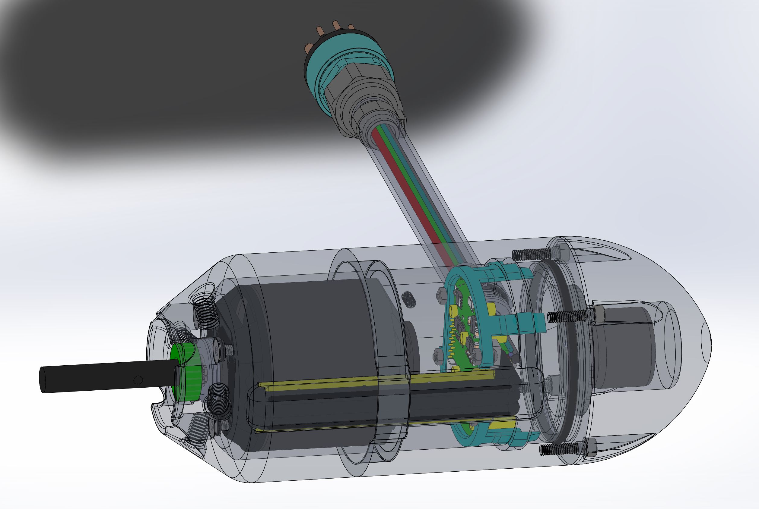
Hey all, I made my own radially arranged ESC for in-thruster operation. Like, the ESC goes in an oil filled thruster, or gets potted or something. It is intended to be installed forward of the motor, like near the nose. Most ESC’s would be perpendicular to the prop plane, requiring a longer thruster body. This one is parallel with it so the body doesn’t need to be especially long. It will fit into a 2.5" diameter cylinder, with openings on top and bottom for wires to go round to plug into the bullets.
The design is based on a VESC. The VESC has some well known problems with the DRV830x drivers at high current, so I replaced the DRV830x with better drivers that can handle more power. It has CAN bus, RS485, TTL serial, PPM, and analog, like the VESC. It works with a standard VESC 4.1x software build.
I guess I am wondering is: Would anyone in this community care or like to use this design? I made 5 for myself but if more people want them we can team up and make some more. If nothing else I’d appreciate help testing if anyone is interested. Design isn’t set in stone either.
I haven’t been able to get a good test out of it as I don’t have a swimming pool or hot-tub. I tried a cattle trough but its not deep enough and the prop sucks air.
Reallly good job !
This is actually what I’ve been thinking about for a long time but I’m not so good with electronics.
What are the caracteristics ? Same as a Vesc 4.XX ? 12S, 50A - 100A Burst ?
Tested it today on a Mejlik 24" model airplane prop with a KDE 7215 135kV. Ran it at 48V. I got it to 80A (~2.5kW). The fets stayed cool but the anti-spark circuit was a little overheated. I added the anti-spark because its a nice feature to save connectors and ripple cap, but it may be more of a liability. Tomorrow I will bypass the anti-spark and run it up again.
It should hit 120A continuous motor current without the anti-spark. Hopefully it will hit 160 . I’ll try running it at 60V as well. Of course this is in the air behind a giant fan. I’ll try and get a video and some numbers tomorrow.
millesth, the black cylinder is the capacitor as you say- it could be multiple smaller caps, that’s just a placeholder until I have test data. In my thruster design I was planning to use the nose as a 1atm pressure vessel. In an e-foil design it might be better to pot the whole electrical assembly, with a heat sink to water on the back of the board.
The goal for my thruster was 100A continuous @ 52V or 12S battery. Hopefully I can get 120A @ 60V. E-foils seem to need a lot of power! Maybe I can push it to 160. Going to call that a stretch goal if power dissipation is low enough at 120. I could do a two board “stack” design with logic on top and switches on bottom if this one can’t get people up and foiling smoothly.
What is the initial purpose of your pod design right now ? More of a paddle pod or is it meant for an efoil-use ? Looks very slick !
What I was initially thinking about was to attach the ESC parallel to the propeller plane (like your design) to an aluminium part with thermal grease to dissipate the heat from the drivers. This aluminium would need to be in direct contact with the water and could be linked to the stator of the motor as well as the ESC.
This way this could provide a great passive cooling for both ESC and motor.
A lot of custom parts and CNC but worth the shot if it works !
Looks amazing, Id certainly buy two if they could handle the current. I don’t know much about electronics design, but is it hard to ad a daughter board of more FETs to increase the current capability without changing the FET drivers to beefier units?
Your idea is very similar to mine- great minds think alike!
If you see my existing thruster above, I would like to re-do the design without a shaft seal. This means the outrunner rotor is in the water, and the stator windings are potted. This requires a special custom stator housing which acts as the electronics housing, heat sink, and allows the bearings to come out the back.
I built the design in the video above because the special motor design will require an order quantity of 50-100 $100ish motors from the factory, and I don’t have that much money
This design will also be very closely tied to the ESC design, since the stator housing is also the ESC heat-sink. I’ll throw up a concept this weekend or early next week so you can see. If we can get people on board we could make some kickass thrusters for super cheap. All you’d need is the foil board, a battery and a controller.
So If I understand properly, your idea is to design a custom outrunner motor with the rotor turning on the water with no water protection whatsoever, probably guided with ceramic bearings, and the copper wires from the stator protected inside a sort of housing that is used for waterproofing as well as heat sink ?
Sounds like a pretty difficut but cool option !
Maybe the only down side I can see is the eddy current (as mentioned by Powerglider for my setup) induced by the rotating electromagnetic field around the stator housing.
Very interesting, but 2.5" is still a bit too large, the ‘standard’ propulsion units here have about 56-57 mm inner diameter due to the SSS motor. It needs to be flush with the aluminum tube so you cant really makr ot bigger. And it would not be elegant to make the nose larger.

 . I’ll try running it at 60V as well. Of course this is in the air behind a giant fan. I’ll try and get a video and some numbers tomorrow.