What about bolting the ESC to an aluminum brick to be a heat spreader, and bonding the heat spreader to the inside of the cooler with epoxy? My fear would be that the fets themselves get too hot because the board has such little thermal mass under the low side switch drains.
Also, without test data, my opinions are just ravings on the internet. I could be totally wrong. I have engineering PTSD and so I am far to conservative sometimes, and I still miss things like @PowerGlider rationale for using non-conductive hardware. I wouldn’t have thought about the board getting wet but it is a possibility in the ocean.
For this level of power and thermal dissipation why not using metal core PCB? It will add to the BOM for sure but I believe it is the way to go. Also instead of kapton tape for thin isolation silicon thermal pad would be better option. It will give great thermal conductivity and electrical isolation
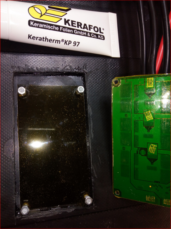
Here you see the M3 stud screws glued into the PR158 through the 0.1mm GFK and Kapton 0.05mm thick.
They shall press the board down by nuts.
The boards back side also has a Kapton foil from the production. It has a roughness of approx. 0.05mm, the via stitching fields which carry the heat are prominent.
The only question remaining is, what is needed in between? Is the Kapton needed? I would say, one Kapton sheet is enough, because i do not trust my handmade GFK, i would vote for one.
Which of them shall remain?
The other open question: Shall i use thermal paste which is specified with 5W/m.K or are there reasons to use other stuff, and what exactly? Time is getting short now for me, only 2 days left for changes.
Very nice ESC: 310€ (290usd exVAT) + shipping. Runs with VEscTool.
What would be the PROS and CONS of this one over the Trampa VESC 6 PLUS ?
VESC 6 PLUS: 248€ (245USD exVAT) + shipping
Yeah, i pressed it slightly, waited some minutes and continued pressing the center where i had the heat paste bead. The sauce came out at the sides first, so i continued with more pressure on the ends until it came out there. Waited some minutes and began tightening the screws. Now it looks static.
@samisin do you have good source and experience with such? I think via stitching is also some cost factor. Kapton is not so bad at higher temperatures. And it is thin. Which thermal pad can i use?
This is great solution for all of us I would be more than happy to help.
I have done lots of power stuff. for work. I will get you some resources on metal PCB later. Having vias on and around mosfets pad’s coppers specially on the thermal pad area will give more mass and way better thermal transfer Which I don’t see in the current PCB design. Kapton thermal conductivity is very bad. use silicon pad (which is designed for this purpose) and thermal paste to fill up any gap in between.
For thermal pad/sheet check below: https://www.digikey.com/products/en/fans-thermal-management/thermal-pads-sheets/218?k=silicon%20thermal%20pad
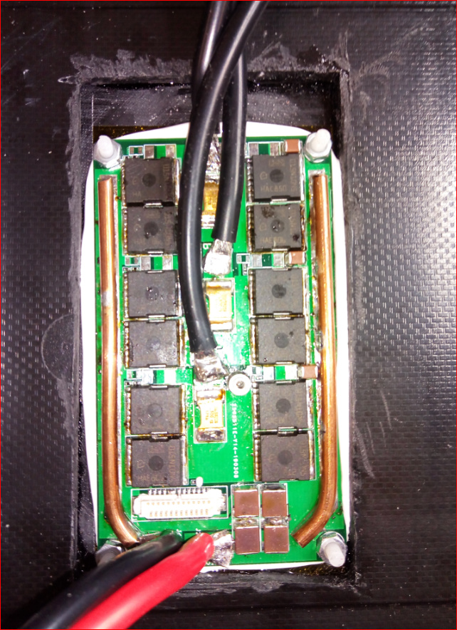
Ahem. Its a 4 layer board, 1mm thick, and the mostfet pads are literally solid vias. I was a little worried that id drilled away so much fr4 the board integrity was compromised.
Do you have some design rule specs for al-core? Like min hole to hole, min plated hole, and stuff like that? I would like to do al-core but i havent been able to figure out the rules yet.
Nick,
It is not that complicated very similar to how you design for FR4. You can find tons of resources online as I found below links very practical.Problem is I don’t know any cheap PCB house that they make metal plate. I wish you could share at least pdf version of your PCB design just for review here. One recommendation I would make is to dedicate enough copper plane in all layers for fets thermal pads and connect the layers thru thermal vias. This will also let the solder to fill the vias all the way to bottom and increase the thermal mass and reduce dielectric thermal isolation. With this, external bus bars and good heatsink you might be able to avoid metal plate and reduce the costs.
Ran it again today at 110A, 55V. Video below. The temp rise is about 1C/4sec. The hottest thing is definitely the gate drive power supply. Fets are around 10C hotter than the board report. I would be comfortable setting the temp cutout in the 130-140C range. The fet packages would be 140-150C, and the die shouldn’t be much hotter than that.
The testing is definitely limited by the motors. I need new motors to get here
I would not recommend to raise the temperature limit. I tried this once with a VESC Enertion FOCBOX and it died within hours. I think the FR4 is degrading at such temperature and also my handmade GFK sheet could suffer. I will start my tests around 85A motor current limit and see how it goes.
Testing at this power class seems to be problematic. Cooling is the clue as always. What motors do you use? Is it 80100? Can you put them under water?
Your thermal camery is a good tool, i see the logic board is heated and also the cables get hot.
I will stay with my fan inside the housing to cool the cables and capacitors.
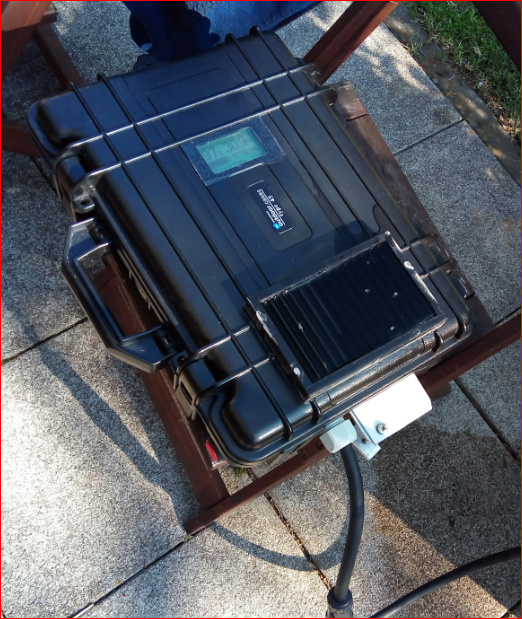
Here is the engineering test, 5kW, 60V 100A input, 150A motor phase current.
This video shows the “battery side” ripple that a user would care about. It’s a little over 2Vpp at 150A motor current. Not sure if this is a deal breaker.
I think my golf cart batteries are still not quite powerful enough to supply the burst. They’re dropping from 60V to 50V, so the power is 5kW instead of 6kW. I’d say it is approximately comparable in size and weight to the Freefly ARC200, except it can do 14s. Obv the mechanical design still leaves something to be desired- if only I had corporate funding and a machine shop…
Finally it’s time to make some more copies for testing in a real world application.