Simmerring
Greetings Frank
Simmerring
Greetings Frank
I think the Simmering is mounted wrong direction.
Lipseal ? I dont think so. It won’t even touch the shaft…
Look at the draw 
Best regards Frank
That’s a contradiction in itself. If the radial bearings are correctly seated, they wont absorb any axial forces (since you ideally place them with axial play). The whole axial load will be held by the axial bearing.
as long as the outer ring of the radial bearings can move, the axial bearing will have the load.
Otherwise put dough before and after the axial bearing and check if it gets deformed by applying load.
If the motor bell transmits the axial pressure from the prop, it pushes in this case first against the radial bearing, which should not be.
The radial bearing can only pass the pressure, if it has so much play in the longitudinal direction that it can walk nicely in the bearing seat, which should not be.
You can easily leave a radial bearing away and have enough space to put the thrust bearing in front of it.
The actual structure is a good idea!
Greetings Frank
The radial full ceramic bearings have an axial play with almost no load of 1/20mm = 0.05mm which i measured.
The brass washer has 0.2mm width not 0.1mm like i draw.
I try to measure the axial play of the combined and preloaded bearings, there is some elasticity around ±0.02mm but it returns to the zero position always. So i resume the bearings are preloaded and there will be no axial force beared by the radial bearings under load.
I had to press in the radial bearings by their outer ring.
If you have a press fit or not does not matter as long as the bearings are sticking out a little from their seat before you glue and/or press them in. There is no need to do without the second radial bearing.
Tested today under water with no load and there was some noise after some minutes. Disassembled everything again, found a plastic piece i do not know where it came from. Than judged the bearings again and found i had too much preload between the thrust and radial bearings. Too much friction, so i loosened the radial bearings a little bit again until i could feel a minimal angular play when only loading the radial bearings. Before there was no angular play. What do you think?
Please leave you comments before i invest another hour of assembling and testing.
If you leave out a radial bearing and put the thrust bearing in between, you will avoid all difficulties.
A radial bearing is completely sufficient for the low forces.
Best regards Frank
Do you know this for sure? You repeatedly write this, but can you prove? I thought about this solution as well, but came to different feeling. I want to make the motor better in some means, but i do not want to make it worse at another place.
Have you done like that? With all the new difficulties? You need a sleeve ring e.g. 16x19x0.2mm to prevent the axial stillstanding part touching the spinning radial part. You can glue it to the axial stillstanding part. Now the axial force goes through the outer ring of the single radial bearing in its weak seat. Should be glued. The konglomerate is also 0.7mm longer. You need to move the rod to hit the snapring groove and have a larger gap.
If i were to produce the motor from scratch with an additional axial bearing and sealing i would do it the same way i did it. There is not only the problem of doubled load for the radial bearing itself (9 balls), but also for the bearing seat in cheap aluminium. Plus the worser lever.
This “simplified” solution implies for me to buy a new motor or at least reconstruct the bearing seat by a ring i have to glue into the stator where i removed some aluminium to have space for the axial bearing.
For what I did if that can help on my last setup ( before going FR) , I just put my gearbox and a thrust bearing after the prop , not even screw the gearbox on the tubing , about 1mm axial and radial play , the prop was self center when spinning
I don’ t think you can apply this on a outrunner , but for me some play is needed and a shim I needs between the spinning plate of the thrust bearing and the center part on the other bearing
Best to put thrust bearing first
A radial bearing belongs on the stator side, and then the thrust bearing, so that the motor bell first passes the load on to the thrust bearing.
Everything else is nonsense!
Second possibility, on the back of the mounting flange, to transmit the forces directly to the motor shaft to the thrust bearing.
Photo of this is already here in the forum with one of my posts.
Best regards Frank
Question. I started that problematic some weeks ago in a German group.
A lot of guys using only 3 radial bearings. I ask is that enough? I can imagine that a trong axis power push to the radial bearings and damage theme quickly.
So my idea was, use on the side where originally 2 bearings, one radial and one axial. It should be enough?
I ask one guy from a special company (skf) if he had such bearings. But still not for a answer because he is ill now.
Did someone know a good axial bearing with the same dimension ( best ceramic ) for my idea?
Ein Radiallager und das Axiallager reicht vollkommen im Stator Sitz aus.
Gruss Frank
Thanxs, i think so too.
But now I need such one and not able to find a ceramic bearing with that dimensions…
SSF10-18M 10x18x5.5 mm
This is the axial thrust bearing i am using in some variation. There are some Ceramic Ball type without SS available. But market is changing.
Build it like power glider …
His ideas are good, just the wrong order for the bearings.
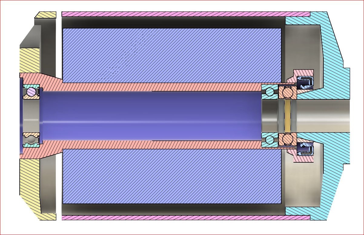
Single Radial Bearing Study:
Very nice 
Best regards Frank
The shim to provide the clearance between axial and radial bearing can be found here e.g.:
If i mount it vice versa, the tension spring would be in sea water. Thats the main reason. Another reason is that the bearing system can get hot and the volume can expand and build up overpressure and i do not want to release oil into the water. You could also try double lip seal.
Most Simmerrings are specified for 0.5bar pressure difference which is a lot. I also thought about a membrane on the closed side of the bearing system to equalize the pressure.
In my last design i had a lubrication nipple at the closed end, but it did not work sufficiently.
There are many solutions available and i am going to add more examples how this can be done.
One way of maintaining bearings which have only sliding rings is to flush it with fresh water after usage in salt water and run it intermittent while the prop is directed to ground. Then leave the water away and let it run at high speed for few minutes. Water has higher density than grease so it sinks down to the last bearing. Than the inner volume will expand by heating and press out the residual water and some grease. Stop it when you can feel the motor is warmed or if you see traces of grease. Flush again, let dry and spin. If i drive in fresh water, i just let it spin with the prop downwards for a minute.