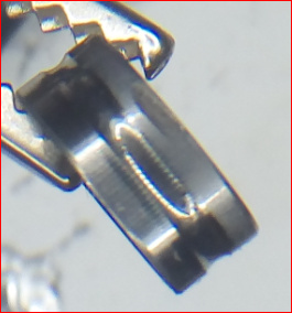
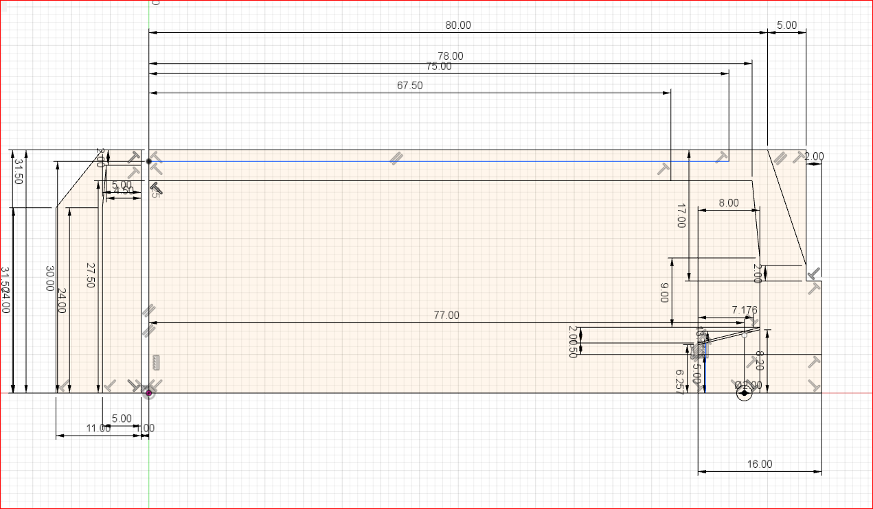
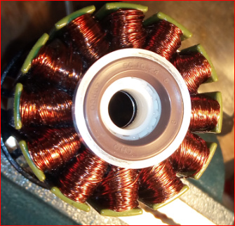
I think the pictures do not show a 63100 but some shorter motor. Also the drawing shows a shorter motor, just <-73-> or <-83-> was replaced by a <-100->. Also i found it very easy to make my own tapped holes and as kotnascher said you can choose your own pattern, so for a three blade prop he made three holes - why not? Anyhow, this motorbell with all its arms is optimized for use in air where you want good ventilation. In water, the closed endbell of the real 63100 is more efficient and allows the use without major modifications.
I also made some holes to my 63100 to have controlled water flow amount across the stator through the rotor end bell. I just ran a test under water without prop: VESC recorded 380W, my BMS showed 490W. I use hybrid ceramic bearings.
I guess you are right.
380W/490W at full throttle? Thats much less than the 80100
I am not sure, if this “no load” test under water reflects the real losses when driving at high velocity, because the radial current it produces is steady. While driving this current cannot build up in this form, because the rotating bell surface moves in a helical path through the water.
This test is mainly testing the surface of the end bell on the outside i believe. Do not overestimate it.
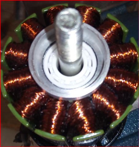
Of course you should have the magnets covered inside the rotor to form a nearly cylindrical face.
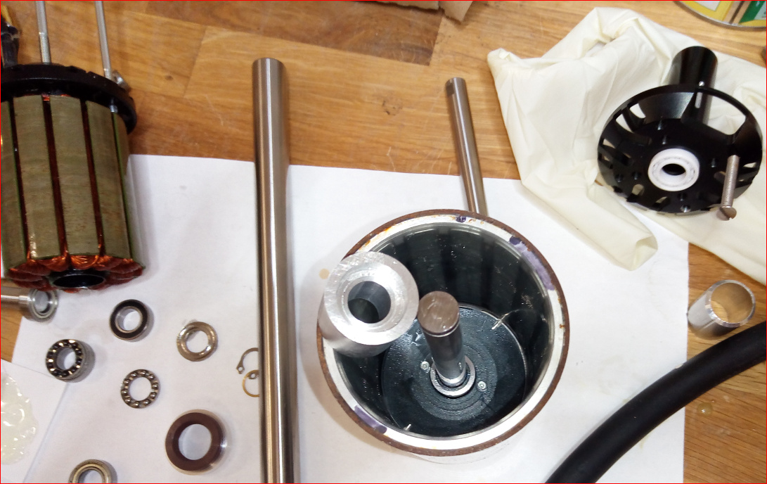
Next thing to solve are the bearings. I use hybrid ceramic bearings and they really performed bad because of a production failure. They produced a high frequent steady noise but only under load. So i disassembled the motor and bearings. Otherwise they were fine, after around 50-70km driving in mediterrian sea there is almost no rust visible on the most outer bearing where there was contact to blank aluminium and sea water.
One of the bearings had a defect from production only visible after disassemble so i assume this was the root cause. It had also a feelable play which already was irritating me when originally assembling.
These bearings contain 9 balls only and the grooves are not deep so now i understand that people were worrying about the axial load and longetivity of this solution. The technical data sheet is also not so promising.
So i search for a solution to integrate an additional axial bearing plus a sealing.
To integrate them i need to work on my lathe, but clamping the complete hub with stator at the end precisely seems to be impossible.
So i will make an adaptor of 19mm aluminium which i turn down to 15mm, the inner diameter of the hub, so i can put the hub on this rod without unclamping it providing excellent precision.
To mount the axial bearing i need a deeper seat with 18 or maybe 18.1 mm. To mount the sealing i need a deeper seat of 5mm with 19mm.
One of the parts i am still missing is the stainless steel polished ring 10x12x5 as counterpart for the simmerring.
I just realized the hole is not exactly 15mm and differs from motor to motor and even within the length. So i will need to make some clamping device with slots, a screw and conical parts.
Wich bearings you bought?
Added link above …
Okay, I ordered not cheap one. Mine costs around 25€ per pice. I got theme from my customer, he have food experience with theme
So what is your experience with them?
I have a customer, he is specialist with such things.
I talk with him about my project and I ask him about bearings. He said, you should take theme.
So I belobe him. I am still waiting for that bearings.
When I got mir informations, I store the info in my thread.
Maybe you can ask your customer if he can have a look at this design and name the flaws?
We have 2000-4000RPM, a bad balancing of the rotational load, and an axial load static 30kg, with peaks from cavitation. We want 1000km lifetime so we need 16 million revolutions.
Okay
20 characters and more
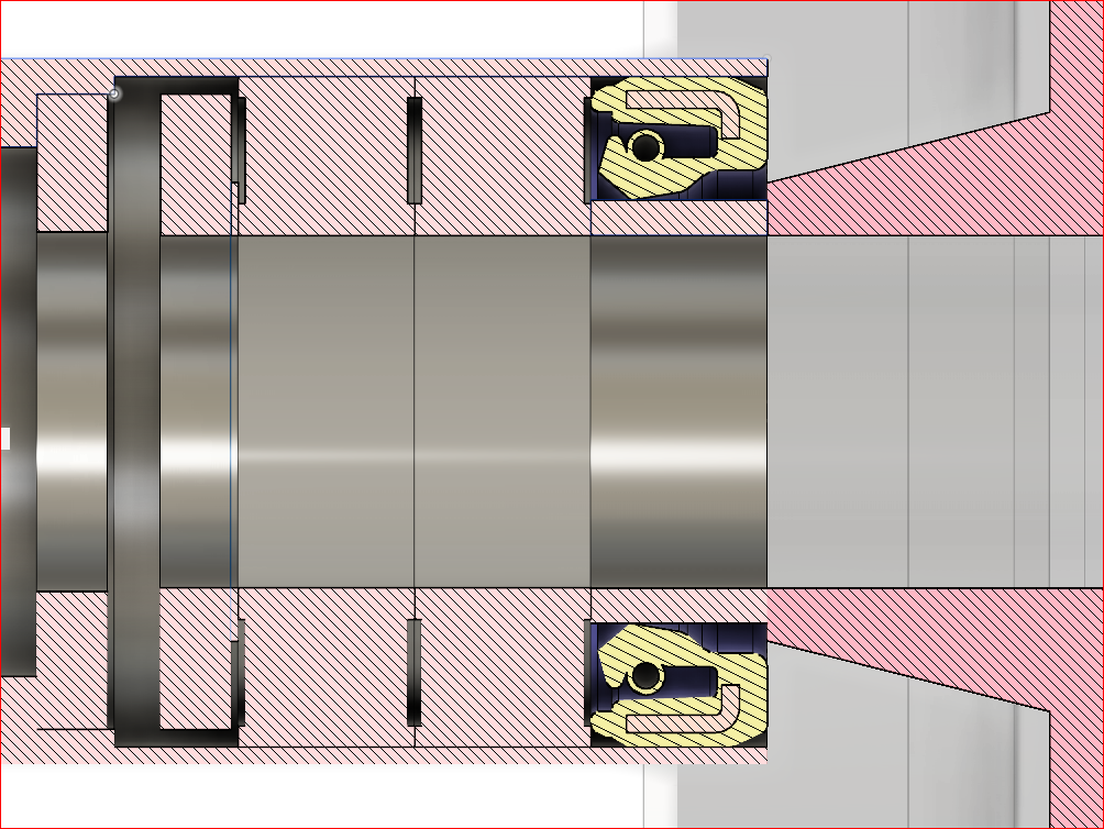
To shorten the design and make it as stiff as possible i made a new approach. I will glue a ring made of a honed and hardened 16mm stainless shaft with conical inner diameter onto the conical aluminium part of the end bell. Additionally i will glue an aluminium part to the stators bearing holder, prolonging it by 5 mm and with an inner diameter of 24mm. This will enable the usage of a 16x24x5mm simmerring.
By this the bearings are completely sealed with a single rotating seal, without changing the stiffness of the original radial bearing design and adding the stiffness for thrust by an axial bearing. All bearings can have ceramic balls, the radial can be full ceramic. This isolates the rotating parts from the standing parts electrically and prevents electro corrosion through the ball bearings.
This is preliminary. It lacks precision here and there. But i think its a good starting point. If some people show interest to contribute i would publish the drawing to support building a community here.
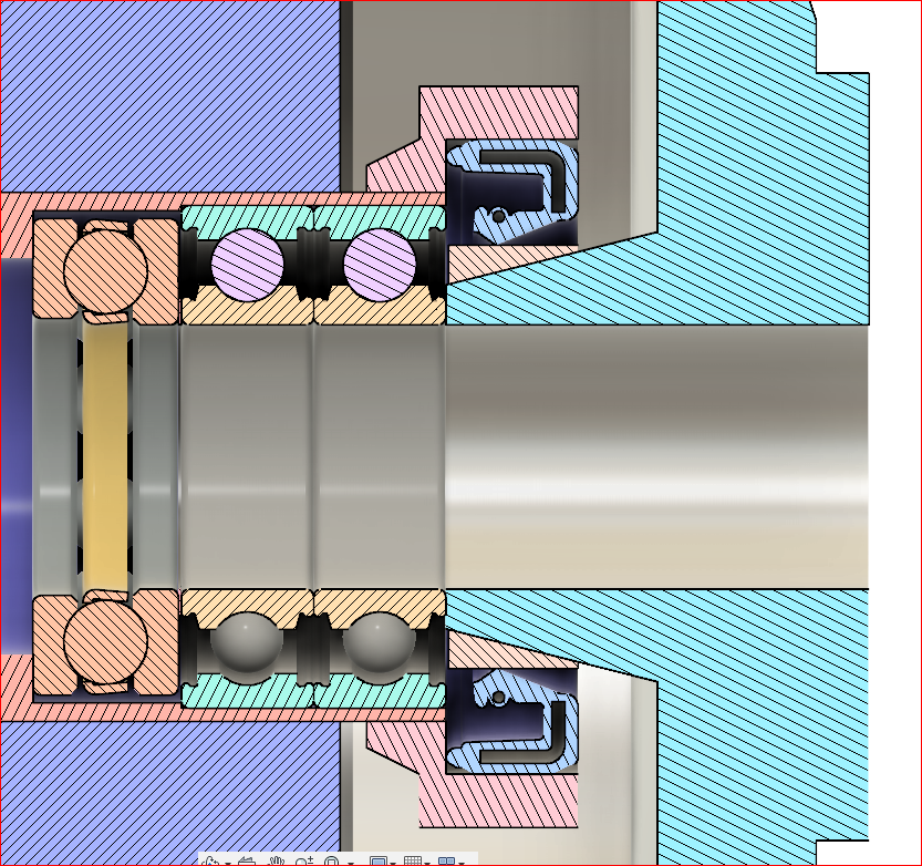
The axial bearing ist wrong at this place.
It’s must before the radial bearing.
Greeting Frank
Please give me a hint why you think its the wrong position.
It doesn’t matter where the axial bearing is (as long as it is at the shaft obviously), as long as your radial bearings are not fixed axial (or have enough axial play).
If i had the axial bearing in front of the radial ones, the lever for the radial bearings is longer, so the system is not so stiff. And there is also a practical reason. I cannot manufacture a perfect radial bearing seat after the whole part was produced and with the stator being glued. The axial bearing can also be placed outside the complete motor at the back. But this implies a very precise mounting of the motor.
And yes, the radial bearings have some axial play but no sliding is possible. So i mounted them with a little preload against the axial bearing.
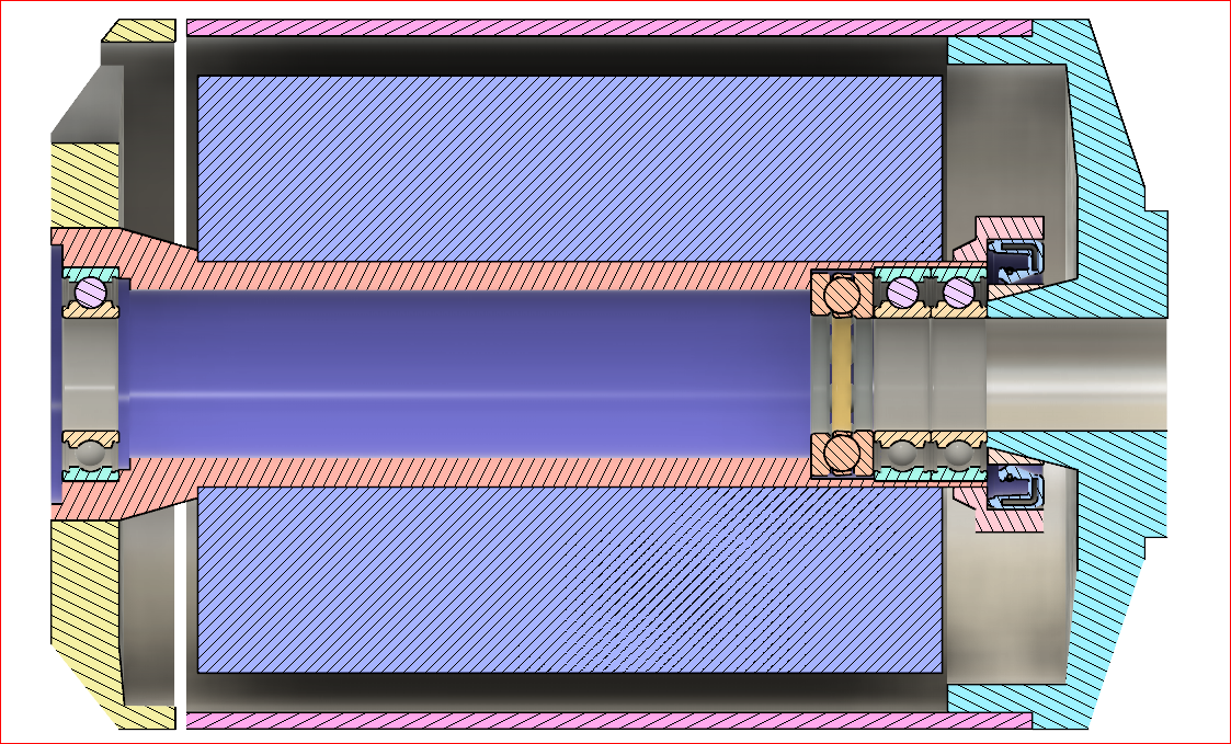
I poured some gearbox oil into the inner compartment.
I mounted the motor with two radial full ceramic bearings, a hybrid axial and a hybrid radial at the back, because it has some sealing lips so i do not loose the oil when handling the assembled motor. Later it is additionally sealed by the back plate (picture in former article).
So i let it run some seconds and the sound is good. Current consumption in air at 12S full speed is 2.9A recorded by BMS and 1.4A by VESC.
If the radial bearings are correctly seated, the axial bearing hardly absorbs the forces.
Behind the engine or in front of the radial bearing is much better.
Have long developed and produced brushless motors.
Beste regards Frank
Yes, this is a clear tendency. My drawing is not correct at this point. I made the cut in a little shorter and also wider than i drew it. This was the theoretical plan at that day and it developed when doing it. I had to press the radial bearings in after i mounted the sealing holder. I used a large washer and a ring covering the outer ring. So now they should be neutral under axial load? Before i used force, the bearings sticked out a little bit. So you might be right. How can i test or check the effect of axial bearing?
PS: Sorry for my corrections, this is complex to describe. Never mind, lets go further.
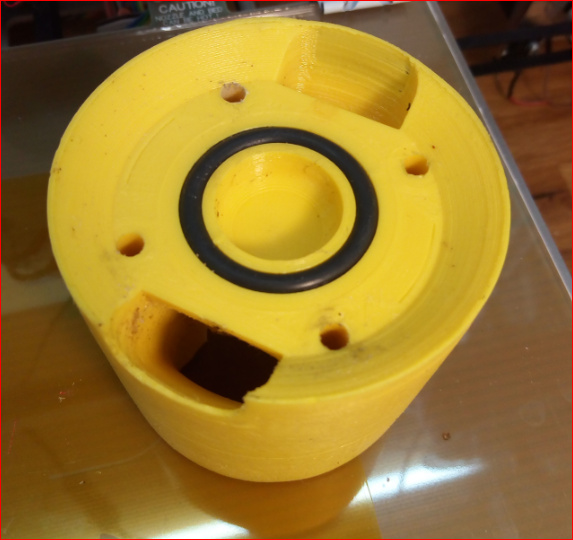
May I ask what this brown ring is and where we could get it ?