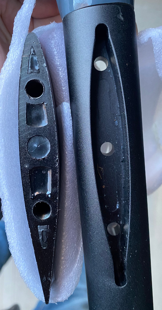
I have a mast that is thicker in every direction comparing the fuselage insert. The holes don’t match too.
Goals:
Make a very rigid connection between the mast and fuselage. Preferably as rigid as usual factory-build where mast fits fuselage perfectly
Still keep the fuselage compatible with the old mast. This is not mandatory but would be really nice to have.
Ideas:
Somehow find some small CNC shop that would be able to scan the mast and then CNC the fuselage. Cost probably will be high. The extra hole or two will not be that good for the fuselage, but probably not too damage to structural strength.
Weld a small piece of the old mast to this new mast. The good thing that the fuselage will be still compatible with the old mast. Probably some risk that the welded seam will not hold the load.
Sand down the thick mast so it fits into the old fuselage. Will need to drill two extra holes on the fuselage. I don’t think it’s possible to sand down the mast accurately so the final outcome probably will not be that rigid.
Or buy a Gong mast at 50usd that should fit into your fuselage female part.
What you need to avoid is that the adapter you develop cost more than on the shelf elements.
The good point with Gong is that the Takuma mast plate should fit the Gong mast 59€ (or 47€ export) for a 65cm mast.
Looks like a slingshot mast. Great masts. Super strong. I use a 90cm.
Just grind the mast till it fits. Use a “flapper wheel disk” in a angle grinder. Mark where to grind, and grind and test fit in stages. That deep aluminum hole mount doesn’t need to be a perfect fit. Get it close, and hammer it in!
.
Good luck!
@Takuma One last thing to check you’re not going to remove 1mm on each wall thickness
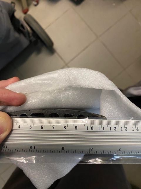
Before launching the grinding process, using a caliper, could you give us the Slingshot mast width and the Takuma fuselage slot wdth ?
SS mast should be around 114 x 15.2mm with 50.7mm screw spacing.
A Takuma surfoil mast is around 109.5 x 14.9mm meaning that the SS mast chord should be longer than the Takuma one.
So your SS mast should need to be cut by 4.5mm (+clearance) and 0.15mm (+ 0.2 clearance) grinded on each wall like the Slingshot mast to Moses adapter below
If you don’t want neither grinding / cuting your mast nor re-drilling your fuselage, you could try 3D printing an adaptor to fit between mast and fuselage:
Thanks everyone! My mast is actually Moses mast, which appears to be the same as Slingshot. However, if that’s the case then I don’t understand why there is need for this Slingshot to Moses adapter:
Can anybody who has Slingshot mast confirm that it’s the same measurement as this:
And my fuselage is Takuma, which appears to use the same mast as Gong and others.
I’m thinking maybe it makes sense to try to build such adapter? I’m just wondering maybe somebody tried this production adapter. Does it introduce flex? Or has any other problems?
I actually went the other way. I have slingshot foils but have switched to a gong mast instead. I found the key to making my mast appear stiff was to run the adaptor up into the mast. That way I get zero play at the foil.
We know for sure that the Gong mast is 14.7mm thick but according to @Alexandre (if I remember correctly), the Takuma mast is a bit wider than Gong’s by a few 0.1mm, so possibly 14.9 or 15mm
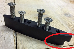
This adaptor (SS to Moses) will not be ideal as :
1- Moses fuse slot is cone shaped with a narrow base (12.6mm above, 8.7mm below), so is the adapter,
2- this adaptor screw spacing is not 2 x 40mm as Takuma/Gong so a third pair of holes should be drilled into it (not fun and fragile)
So you have to use the following method (a calliper is compulsory):https://projectcedrus.com/adapter_fab/
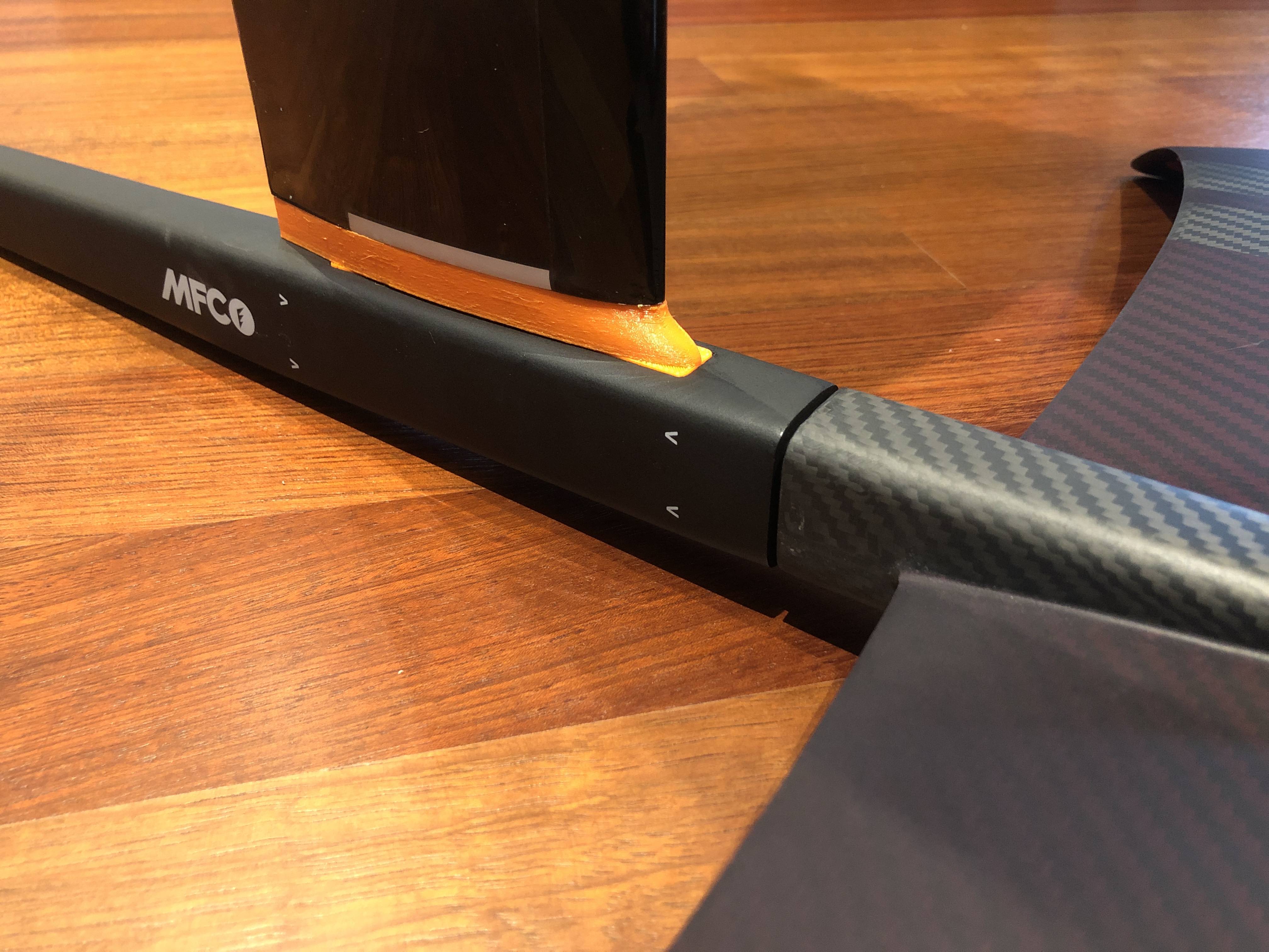
Just to clarify, this image pulled from my website is showing a fitment check of the MFC adapter for Project Cedrus. You cannot 3D print out of plastic an adapter with adequate strength/stiffness to be used in service. So don’t try, unless you have access to a metal 3D printer and can sinter aluminum or titanium parts.
Thanks for chiming in. May I ask why what is possible for the MFC insert wouldn’t be possible with another fuse slot, I mean using a material with high tensile/shear strength (PC max maybe) with a bit of elasticity ? Also because, I might be wrong but is seems that the mast to insert screws take 90% of the strain, the two fuse to insert screws being there to maintain the insert in the slot.
It is not possible for the MFC adapter, either. Again, I 3D print adapters before I machine them to ensure they fit properly. All of my adapters for customers are machined out of aluminum. I did not have a machined aluminum MFC adapter at the time, so I used a picture of the 3D printed part for illustration purposes.
3D printed parts do not even have the strength of Polycarbonate. Depending on print direction, you can have 1/10 the the strength in the Z direction vs. X-Y. Also because of the low modulus of the material, there is more bending load in the fasteners which further increases strain on the plastic. Plastic also has a tendency to soften in water and degrade under UV exposure.
@ProjectCedrus as you have a lot of experience could you tell me do these aluminum adapters decrease the rigidity of the setup? I want to eliminate the flex so I go with a stiff mast, however, this mod doesn’t make much sense if the rigidity will be lost at the adapter. Or do you agree that it would be best to just grind the mast so it fits in the small insert in the fuselage?
How much would cost such a custom adapter including shipping to Europe?
Trust me, I weigh 90kg and have made adaptors for interchangeable systems for:
Gong - Slingshot
Gong - Unifoil
Axis - Unifoil
Axis - Slingshot
Slingshot - Unifoil
I do not notice one single bit of flex in the Gong mast when I foil it with an adaptor to either the slingshot fuselage or the Unifoil fuselage. (but I notice a lot of twitch/shudder with the slingshot to slingshot native system)
Most guys notice the “shudder” where the where the mast connects to the fuselage and think that its the mast that is flexing.
On your system, you need either the mast or an adaptor to properly wedge into the Takuma fuselage with zero play.
If you use an adaptor, you also want it to run up into the mast if it can. This completely eliminates any play.
In which materials where they made ? Have you tried adaptors in 3D printed material only (no aluminium). If yes which material has the best strain resistance ?
I print test adaptors in PLA. Once I am happy with them I mill from of aluminium.
I would not trust an adaptor made from 3D printed material…or even milled “plastics” for that matter.
resin casting with pre-positioned screws could be an option too from a male then female mold of the fuse slot prepared with release agent, the way people mold their windsurfing tuttle or deep tuttle fin base in their board fin slot giving giving an extremely strong and durable fin base.
Aluminum adapters do not have any impact on total stiffness of the system. Assuming adequate fasteners, all of the load is transferred in bearing between the various surfaces. It helps to have a thicker mast to react the short couple between the parts. I’m sorry but I don’t make adapters for other masts, only Project Cedrus.
If you are interested in learning more about structural mechanics of materials, the property “Modulus of Elasticity” will yield the “best strain resistance.” Note that even the stiffest plastics have a modulus of around 2GPa, while aluminum is 68GPa. Yield strength of most plastics are in the 10-20MPa range, and again aluminum is 20x higher at 275MPa. Delrin is stronger, but still 10x weaker than aluminum at 69MPa. The biggest problem with 3D printed parts is you cannot get the fasteners tight enough without shearing the threads off. If your fasteners are not tight, you introduce more bending into the fasteners and bending into plastic. You don’t get good load transfer in bearing and stresses are very high.
The example above regarding the tuttle box is inaccurate. The tuttle joint is effective because the structural component (mast or fin) is encased in resin. The resin simply transfers the load to the structural core of the joint by bearing. The resin itself is never subject to bending loads. Also it’s important to note that there are [metallic] threaded inserts in the resin for the screws. Finally, thermosetting resins used for casting (epoxy, urethane) typically have a higher young’s modulus than thermoplastic polymers (Nylon, ABS, PLA, Delrin/HMWPE) due to the cross-linked polymer chains.
Thanks for the explanation. Aluminium seems to be tailored for the task but requires a CNC. At this point, the best thing to do would be testing the assumptions. However, as we are on a DiY forum, here is a last bunch of questions :
which fraction of the 68GPa (Alu modulus of elasticity) and of the 275MPa (Alu yield strength) would make a durable mast to fuse adaptor ?
Should that be a problem since we are looking for a stiff and possibly strong material ? What are the figure in Pa of a “good” cast epoxy/urethane modulus of elasticity (Young modulus) and yield strength to compare it with thermoplastic polymers?
I have friends making durable threads in an epoxy resin + microsphere mix (unless it is resin + silicate, can’t remember). He is using that for boards, not for adaptors.
A copper IKEA radial bolt type could be used in the adaptor to set a durable thread up though.