Latest revision works great! This revision can handle 120A motor in FOC mode easily. Unfortunately I was not able to make a better video since the dyno blew up (it seems my dyno building skills are not very good). The headline is that it can do some serious power and the electrical switching noise is within an acceptable level.
As @PowerGlider mentioned, this design is far superior to the round design I started with. Like the round design. the components are all on the same side so the board can be mounted to any flat heat sink or cooler. But this design is also suitable for a much wider set of applications. It could be set in the battery box above the waterline, or it can be mounted in the motor tube under the water, or in an e-skateboard or bike or anything.
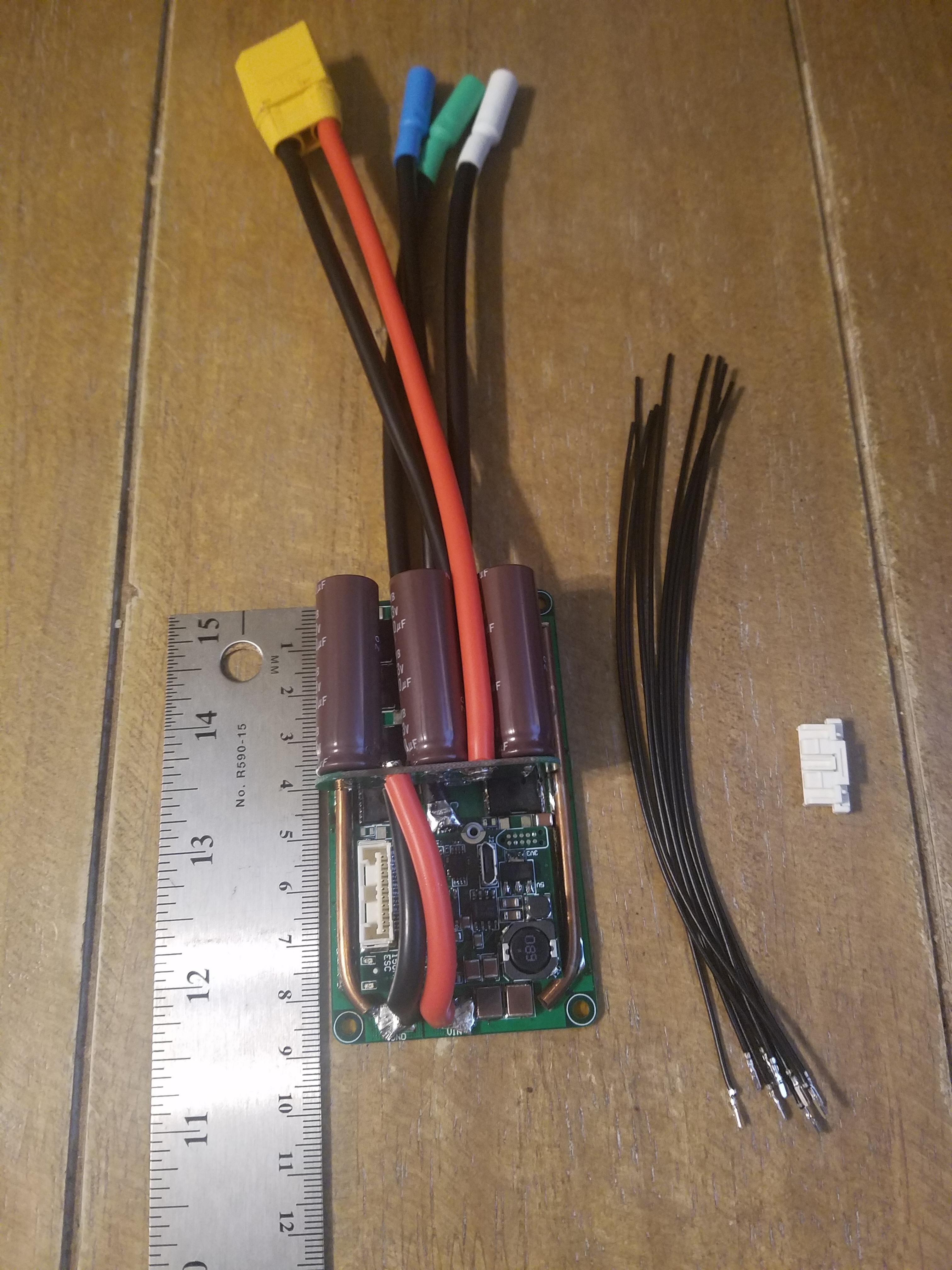
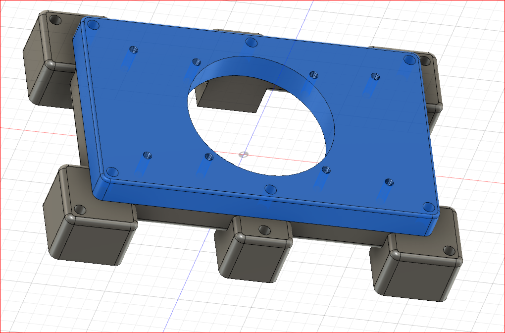
Here is a picture, sitting on a 12mm aluminum block. Dimensions are 2"x3.5" (50.8x88.9mm). The capacitors are intended to sit on top of the phase wires.
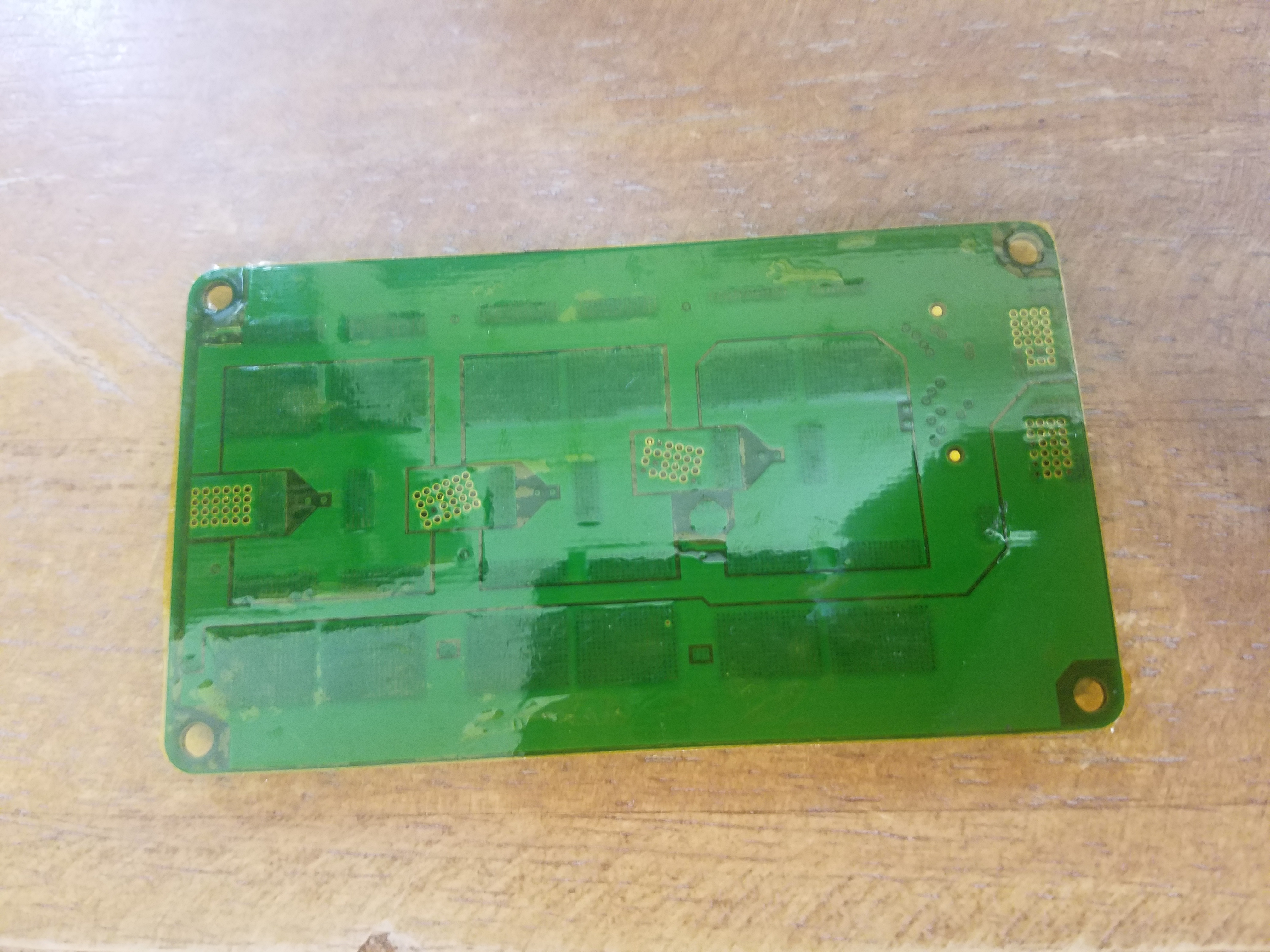
Here is a photo of the back of the board. What is different from most ESC is that the back has no components on it, and thus can be put flat on a heat sink. The vias under the transistors are very efficient at conducting heat through the board, ~1-1.5 C/W. That means each transistor can generate a lot of heat without getting too hot. The intention is for this board to be mounted on a heat plate.
I haven’t seen the inside of a FreeFLY ARC200 or the NOLO pro 110A but I assume those have a similar layout, due to their similar size. I will do my best to figure out how to make this available for an affordable price.
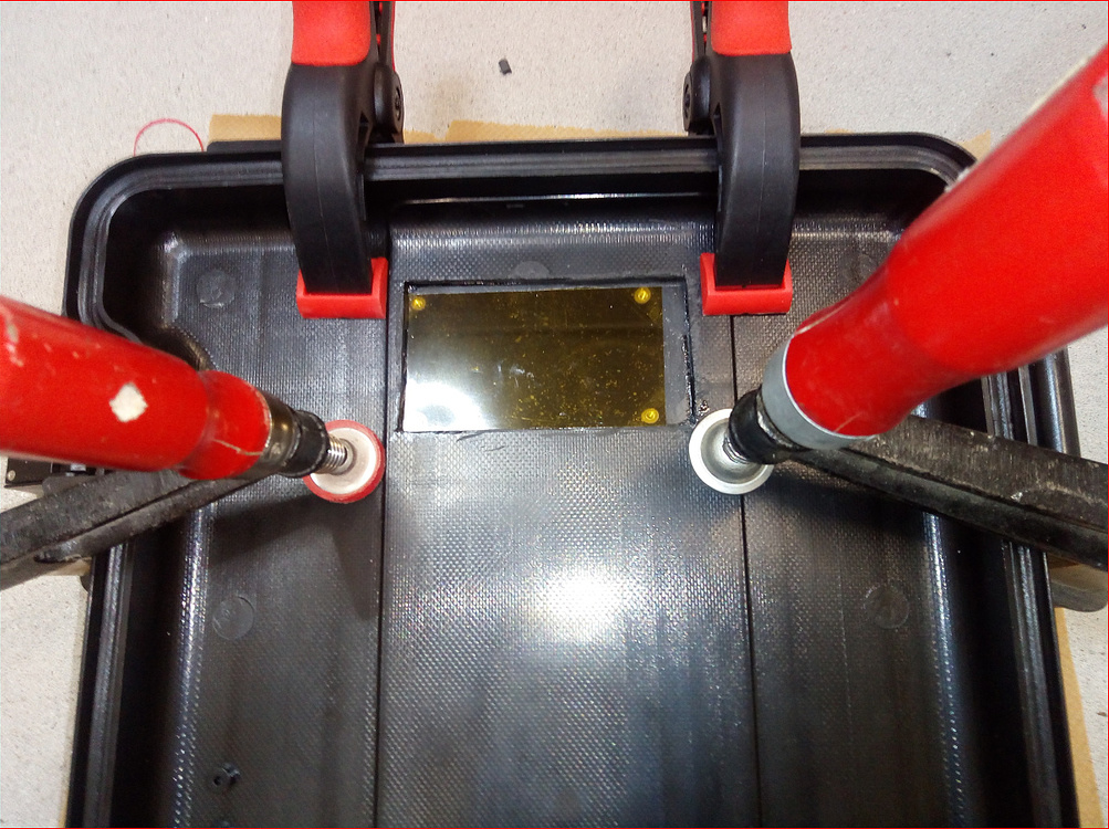
That is kapton (1-mil polyamide) tape. I use it to keep the solder from flowing through the vias and making bumps on the heat-sink surface. Before it is installed on the heat-spreader / water-block / heat -sink, I take it off and put a new piece of tape onto the heat sink.
My theory is that the heat-sink is really flat and the kapton will adhere smoothly to it without trapping any air, while the board is lumpy and bumpy due to the copper etching and board warping and stuff. So I put thermal paste between the pcb and the kapton to fill all the lumps and bumps.
@nickw1881 I’m very interested in your design. It seems to be very well made and thought. I really like the coolling side free of any component, the big mosfet with the copper bus bar and the dual pcb design. What is the continous and max current that it is “rated” for ? At what price do you think that your design can be sold ? If you want to sell some of this babies, count me in. Thx !
I cant say how much power it can do until I get test data, and itll be another week before I can get test data and video. I’m waiting on a bunch of 1kw power resistors to dissipate the load. Im very impatient so all the waiting is killing me.
I sure hope itll do 150A @ 60V. I have reason to think it will, but you never know until you actually run it.
The price isnt going to be good. Theres so many low cost 12-14s 200A esc out there now I almost regret making this one. Maybe $240 ish
For the low cost 12/14S ESCs out there, there is no good one at not to expensive price, Flier ESC and other are not very good quality and prone to smoke. And no one support FOC. And the mgm, kontronics, yge, schulze-elektronik are all very expensive and/or for helicopter
It is very difficult (impossible in fact) to find a well though, well ingeneered, well built VESC6 with high current/power capability, other thant the one sold by tampaboards wich is very expensive too… So I think there is room space for your ESC.
If you know a 12/14S high power, high reliability, high tunability, usable in all application AND for say, 250 to 400$, let me know !
Well, that is every VESC6 based ESC (any other, not OS ESC, will lag the tunability in some point; for 14S only with 75V or higher rated fets; the 60V ones wont like 14S).
High power only depends on your ability to cool it. The standard VESC4.12 has mosfets good up to 245A continous…if you are able to keep them < 25C…maybe with liquid nitrogen cooling.
So most realistic and most likely in stock there might be this:
e class="onebox allowlistedgeneric" data-onebox-src="https://teamtriforceuk.com/a200s-v4/">
TeamTriforceUK
Still I think this price is quite good. Especially if you take into account that you cant compare a self developed and tested ESC to some china versions where you see a 30secs video like from Flipsky…sure they are cheaper, but this is as well what you get.
Prototype arrived today already! Thank you Nick!
First no load test showed perfect behaviour! PPM Input is working fine.
Tomorrow i will work on the cooling concept.
The design is really compact.
In the past months i read a lot about special materials and i think we should have some discussion here, because this design is suited very well to test and use such innovative materials for highest power density and miniaturisation.
I think its a good step forward. One can depart the logic board easily to reach every solder point on the power board. When handling for e.g. glueing the logic board with its sensitive sockets it makes sense to remove it and cover the socket of the power board with another empty plug and some tape cover.
Its curing right now.
I had to find a decision, i had my cooler made up with 3 layers of glasfibre 25g/sqm, adding up to 0.08mm according to Laminatrechner - R&G Faserverbundwerkstoffe GmbH
This i covered with additional capton self adhesive. So the laminated cooler is glued to the outside of the battery box lid. Into the four threaded borings i will glue stubs and use some kind of plastic nuts to mount the board. This will lead to almost no possibility to get a connection between PCB and cooler on the one hand and between cooler inside and outside on the other hand. The latter becomes important in case one capsizes and there is water ingress into the box for some reason. In this case water would make a connection between the PCB and the thread stubs. This i need to prevent, because water ingress could happen when capsizing more propable.
Lets assume the GFK is 0.1mm thick and lambda is 1W/m.K . Lets assume the area is limited to the area surrounded by the srews, which is 1.75"x3.25" =5.6875sqinch=0.0036693475m^2.
So the thermal resistance of the part is l/(lambda x A) = 0.0001m/(1W/mK x 0.0036693475m^2)= 0.02725 K/W. That is very low. Even at 250W it would only add 7K.
I assume a Kapton tape would add the same or even less, but its dependent on parameters i do not know. I think the highest resistance comes from the thermal grease and the unevenness of the PCB and the fact the thermal conductivity of the PCB is not evenly distributed.
I just had a look at the roughness of the PCB including the kapton tape and it is around 0.05mm. That would fit to EYG-S091210DP
I had to go my own way regarding the mounting of Nicks VESC6. I have the aluminium cooler outside the box, and i bored it through and made threads for M3. I am using Nylon screw stubs, i just glued them in, for safety reasons. I follow a rule, that there may be only one loose end, one point of electrical leakage, and that is the motor. So the other side, the battery box must be isolated under any circumstance, even if it has water ingress. So it is not an option to mount the PCB to an aluminium cooler with metal screws, because the screw heads sit right beneath the electrics and you would need a single drop of (salt) water to make a bridge to the cooler. As the motor is driven with voltage between 50 and 0 volts, any leakage from plus or minus of the battery voltage to the cooler would cause an alternating or direct voltage differential of different frequency. I got zipped by this voltage before by leaking dead man switch and i definitely do not want it. So i have to keep the barrier tight. So i have to use isolating (plastic) screws.
I also experimented with 3DP cap nuts, but there remains a slot. Maybe its small enough to limit the current by some amount.
I tried other approaches as well, like a frame which spans the complete VESC and has screws to press the board to the cooler without perforating it. It is also promising, maybe i get back to it, 3DP parts can be used. But its also complex and i love simplicity. One needs to mount a lot of screws, if its precise it could work.
 (it seems my dyno building skills are not very good). The headline is that it can do some serious power and the electrical switching noise is within an acceptable level.