@Manu No, I will not sell mine.The Gerber files I have published, is for everyone to order their own, from the manufacturer of their choice
4 Likes
Update on the sun visibility problem
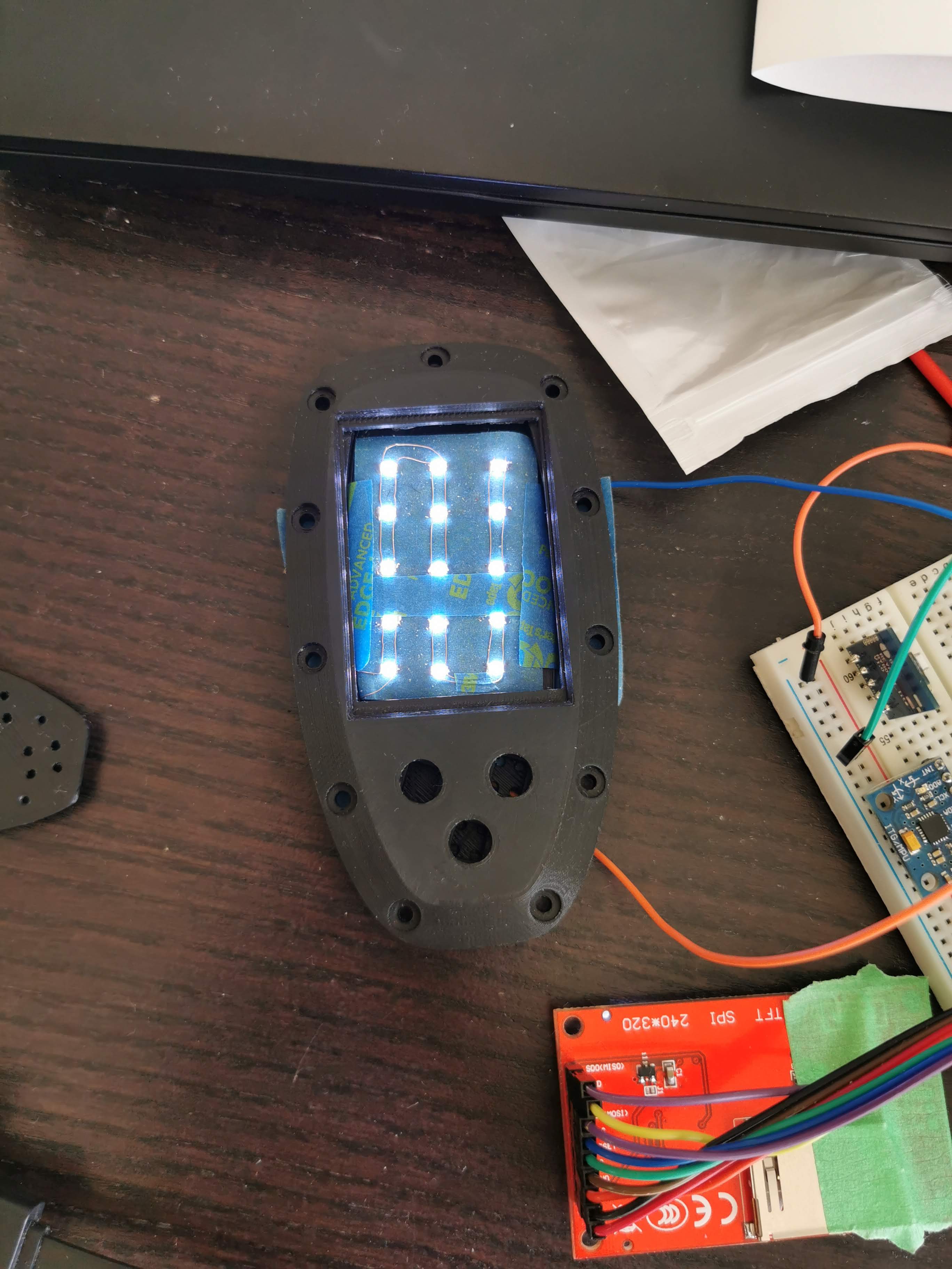
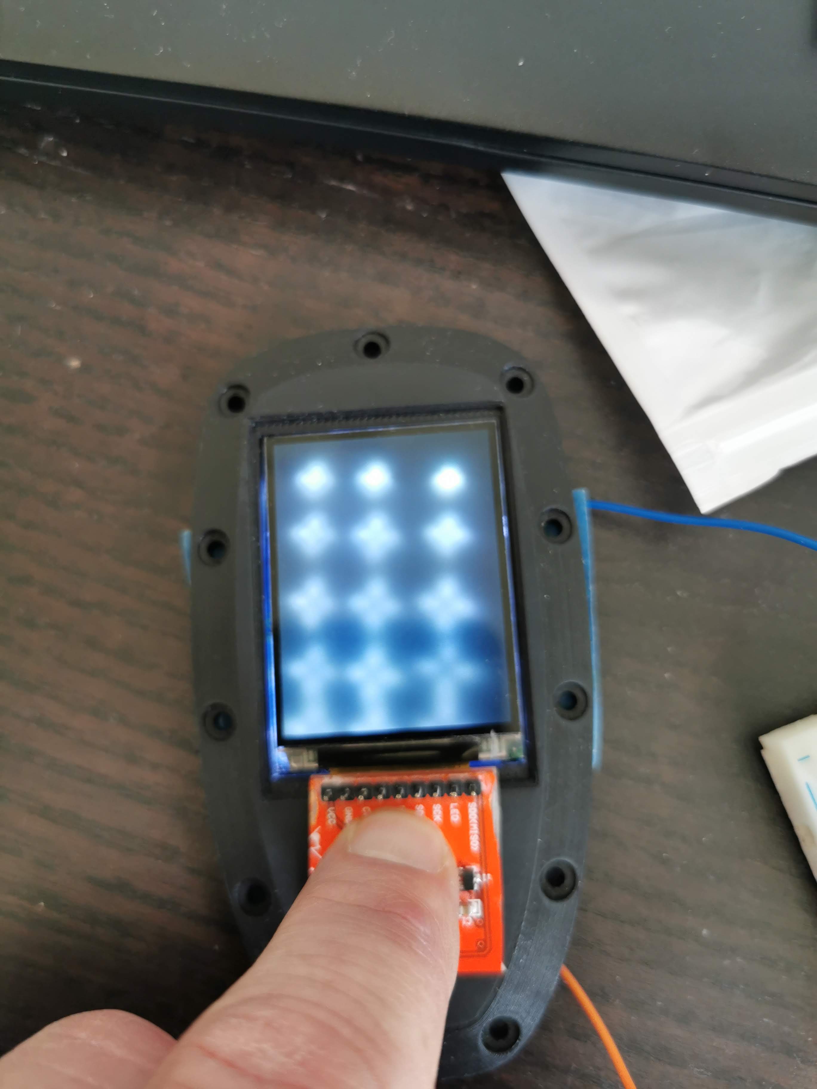
I found 15 small 1206 smd leds in my drawer. Don’t know the specs, don’t remember where I bought them but any how. In the first attempt I just soldered the leds together in parallel and mounted them behind the LCD.
Big failure! I just saw stars and I don’t think any diffuser can fix that problem.
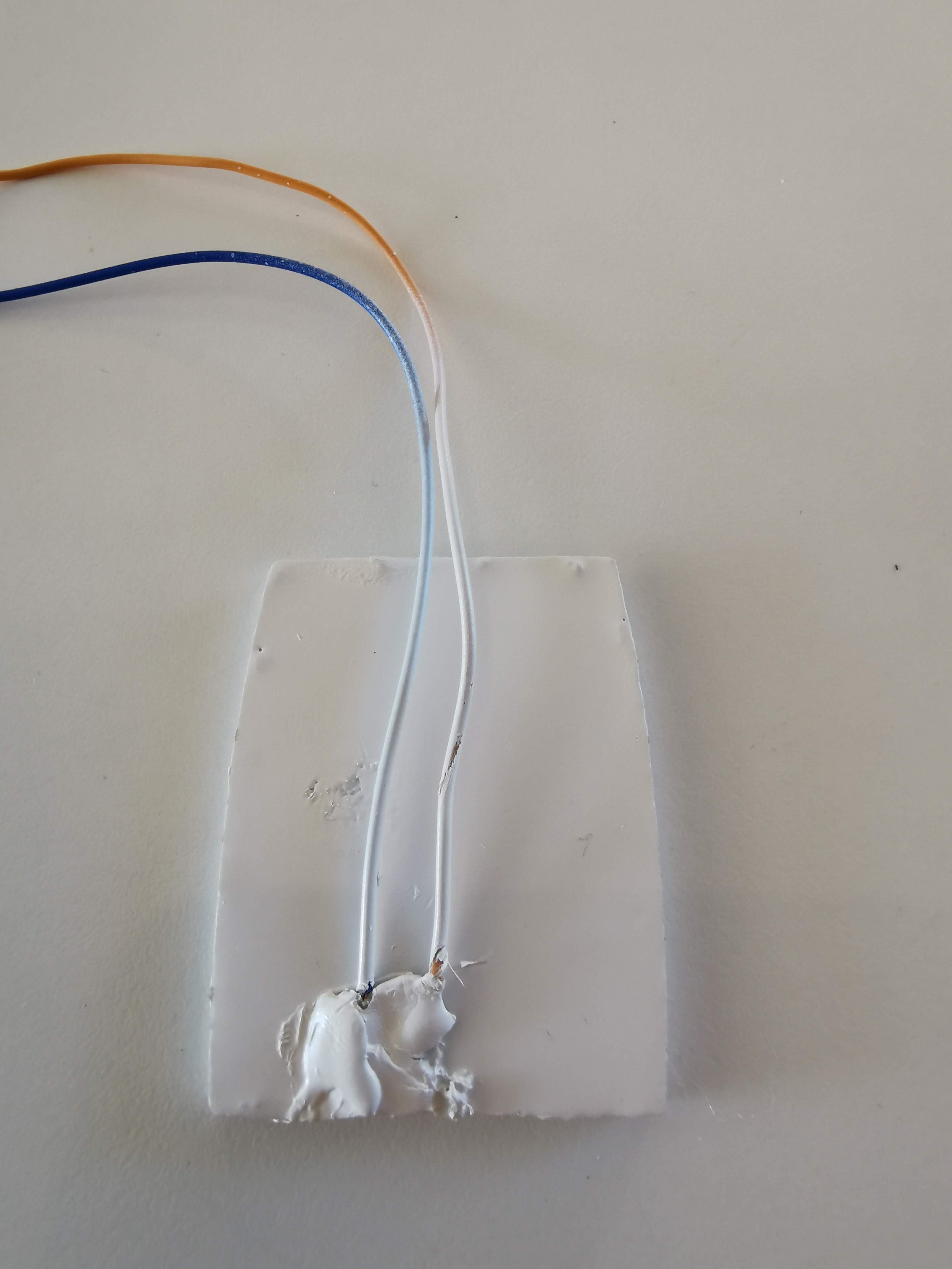
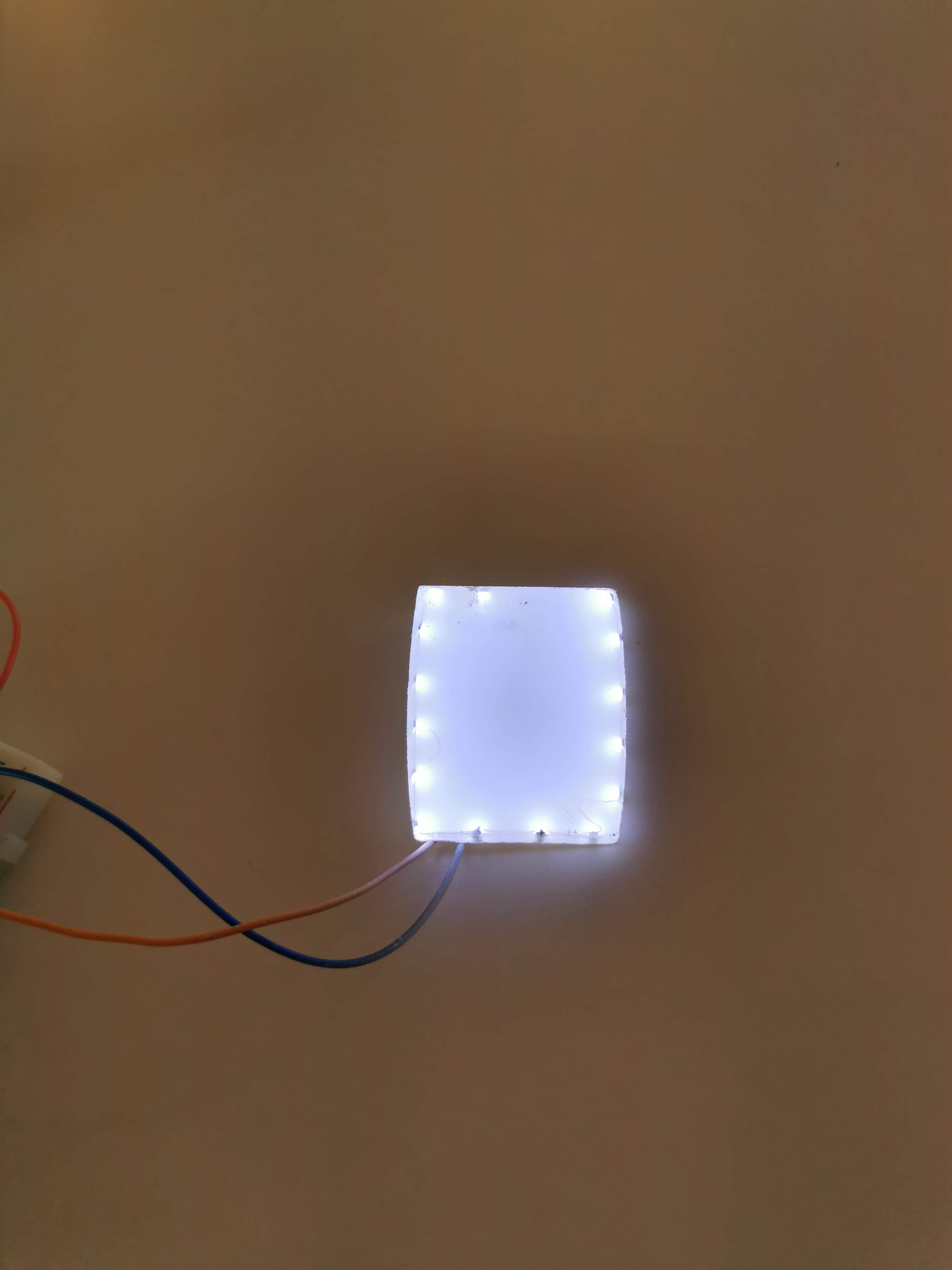
So back to the drawing board. So what if I created a small mould, glued the leds to the side of the wall, filled the mould with clear epoxy resin and spray painted the back and sides for preventing the light to escape. Here is the result.

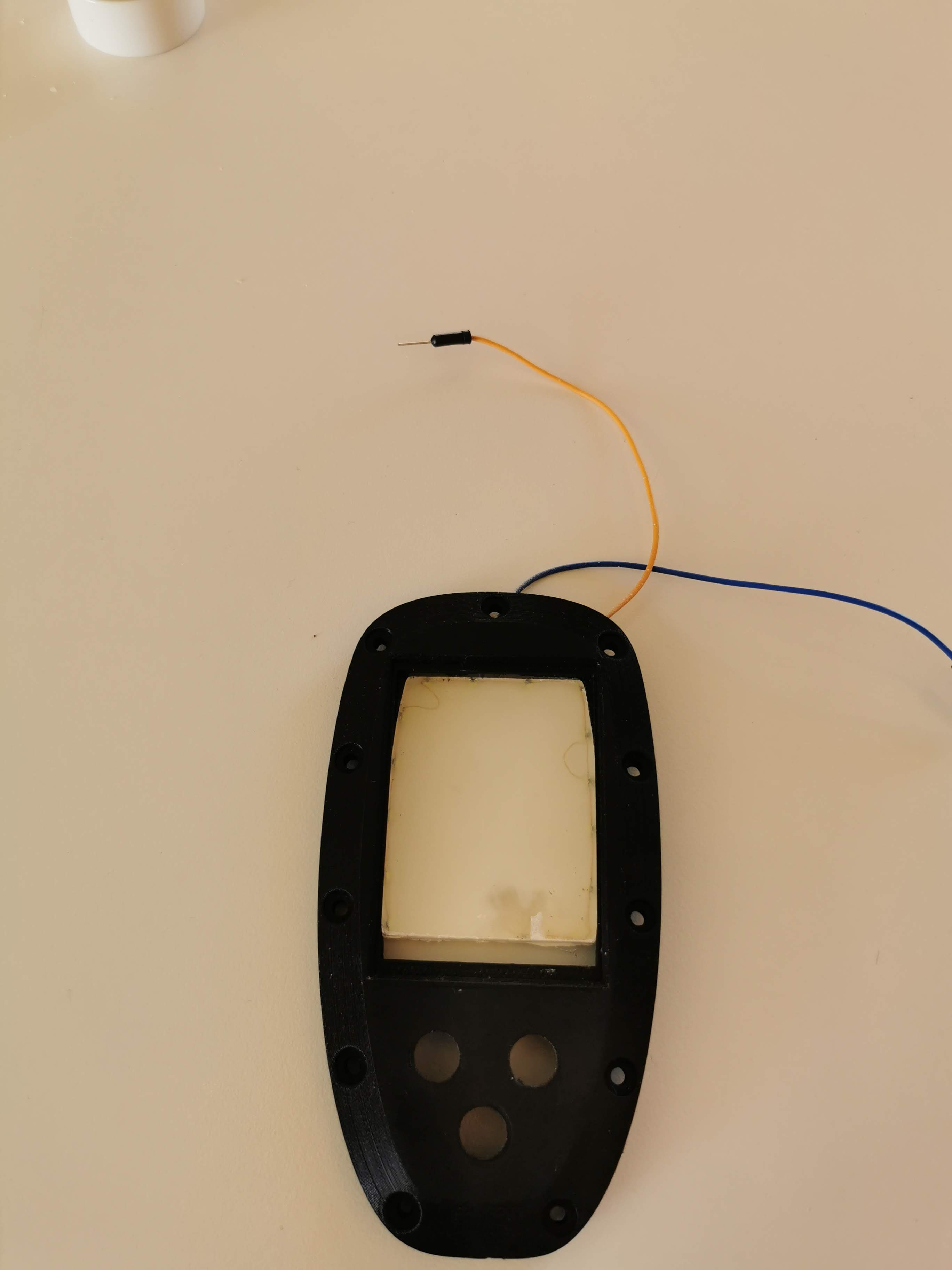
!
It’s not perfect, not as good as putting my torch behind the LCD but I think I’m on to something, considering that all 15 leds only draws 150 mA, that’s 10 mA per led. I’m quite sure I can find leds that draws 20 or 30 mA, have to look that up and order some.
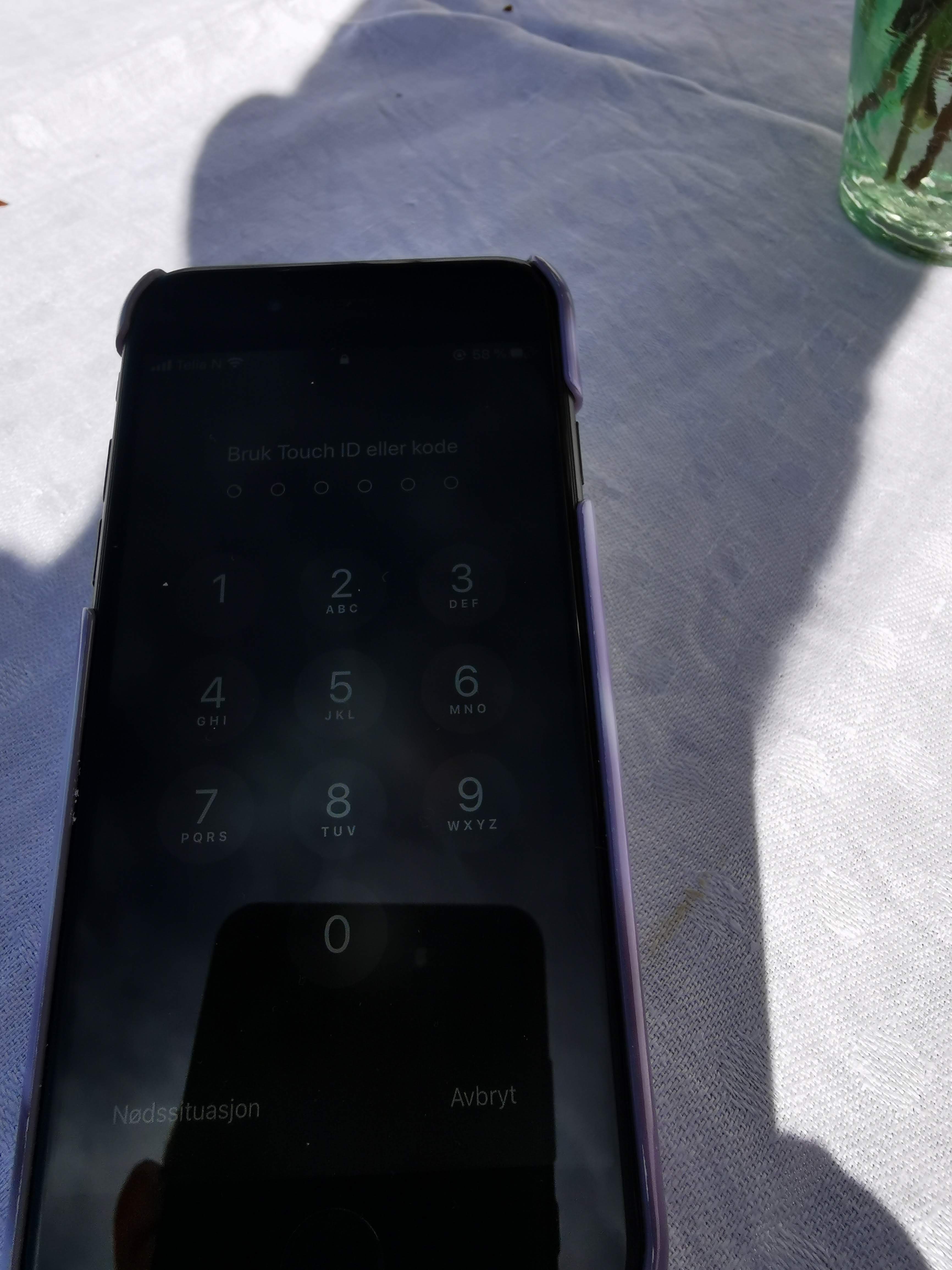
Also, compared to my daughters iPhone 8, I think I have much better readability. No point showing the iPhone in direct sunlight. Didn’t see much.
4 Likes
Hi
Regarding ordering with the gerberfile… would you say that the circuitboard in it’s final version or should we wait a while until you are finished with this amazing remote project.
Br
Magnus
Hej Magnus, alltid trevligt med en landsman på tråden.
Well, I would perhaps wait until I’ve tested the PCB, hopefully later this week If I haven’t had a total barinfart, most of the things can be fixed with small patches. The extra led for sunlight visibility CAN be connected to the existing LED pin on the display, perhaps just changing one PNP transistor (Q2) to a more powerful one. But ultimately I will change the PCB slightly, perhaps a new connector for the extra leds and a new connector for the IMU because it might not fit between the PCB and the display any more.
I will wait untill working circuit board and control. otherwise I will just have to order a new board.
What motor and controler do you use for your foil. Any thoughts about the batterypack yet?
Br
Magnus
I’m using the Flipsky 200A VESC and the FS65161 motor. I will start with the battery pack (13s12p) I used for my Segway a couple of years ago (hopefully it will be enough)
1 Like
How did you make the tactile switches waterproof? Epoxy the silicone caps into the lid or something?
@Mantafoils suggested one but since they are doing well in direct sun light but rather small, what about using two Maytech V2 remote OLED screens side by side ?
I used something called Tec7, It’s a kind of flexible glue.
1 Like
Yes, that might be one way to go, but I have one problem though. I don’t have enough pins left on my Teensy to run SPI on two displays. I2C can perhaps be used instead, but that will slow down the refresh rate significantly.
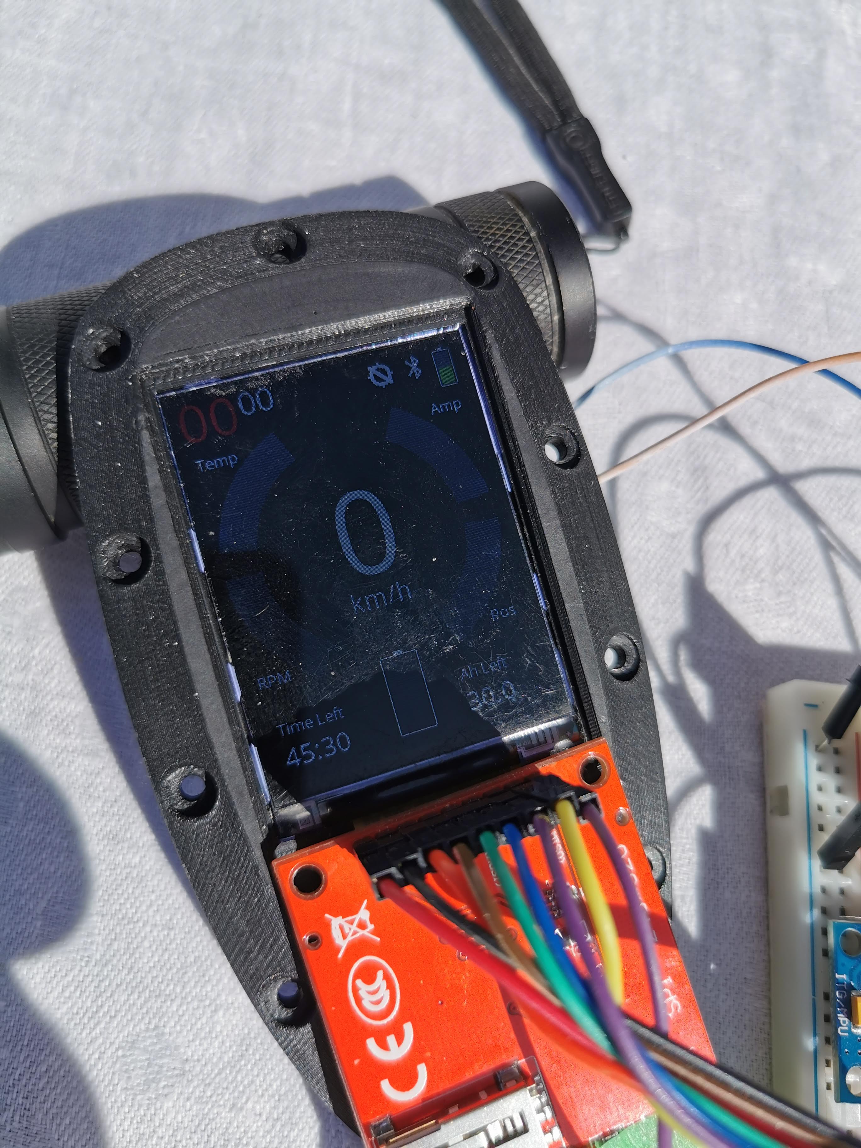
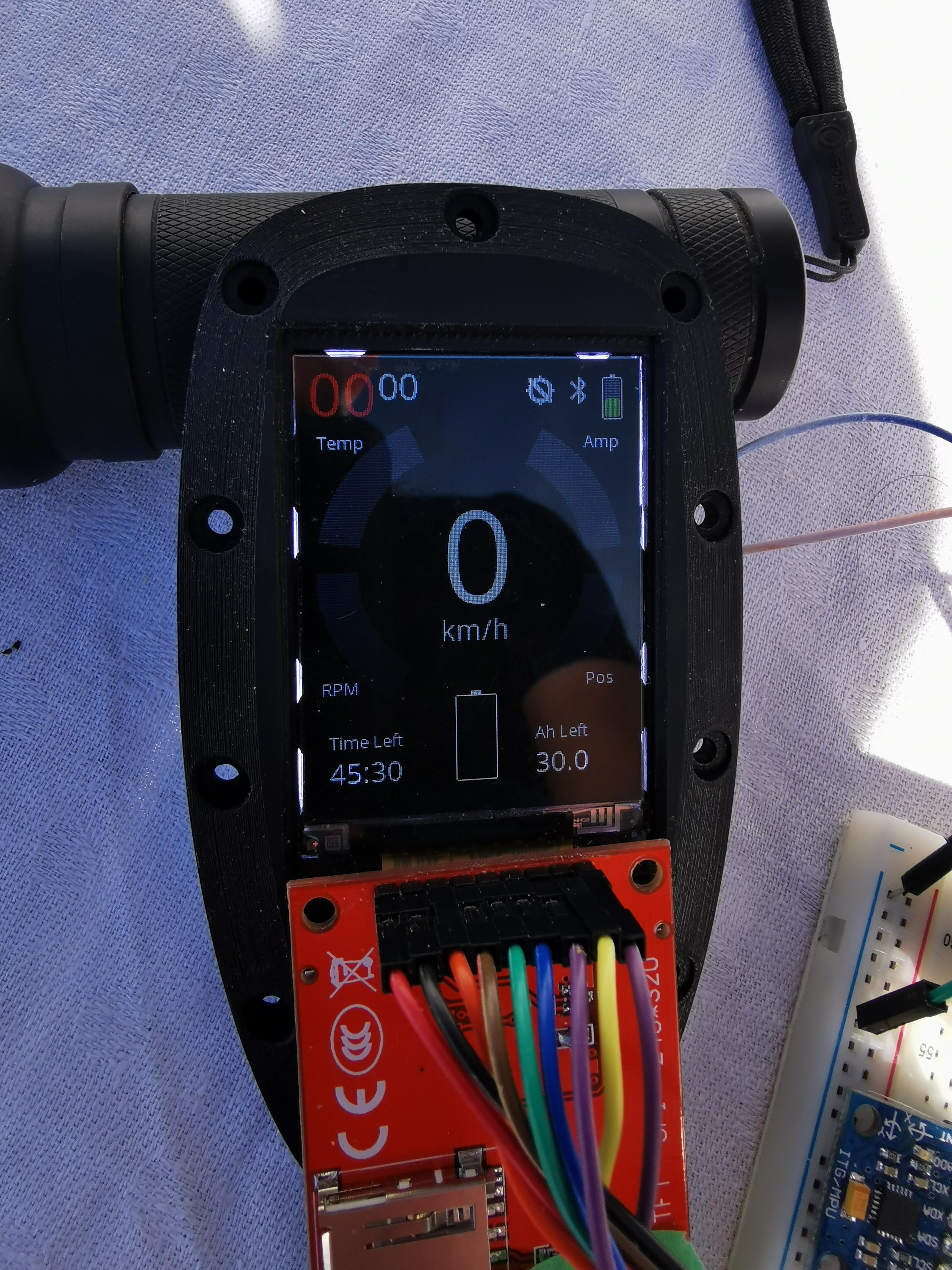
Following @samisin sugesstion from an earlier post, I ordered two Newhaven NHD-2.4-240320CF-BSXV-F displays, and on Friday I got a package from Mouser. After spending some hours coding on Saturday I finally got the ST7789 driver to play with my Teensy and luckily we had some sun today and here is the result.
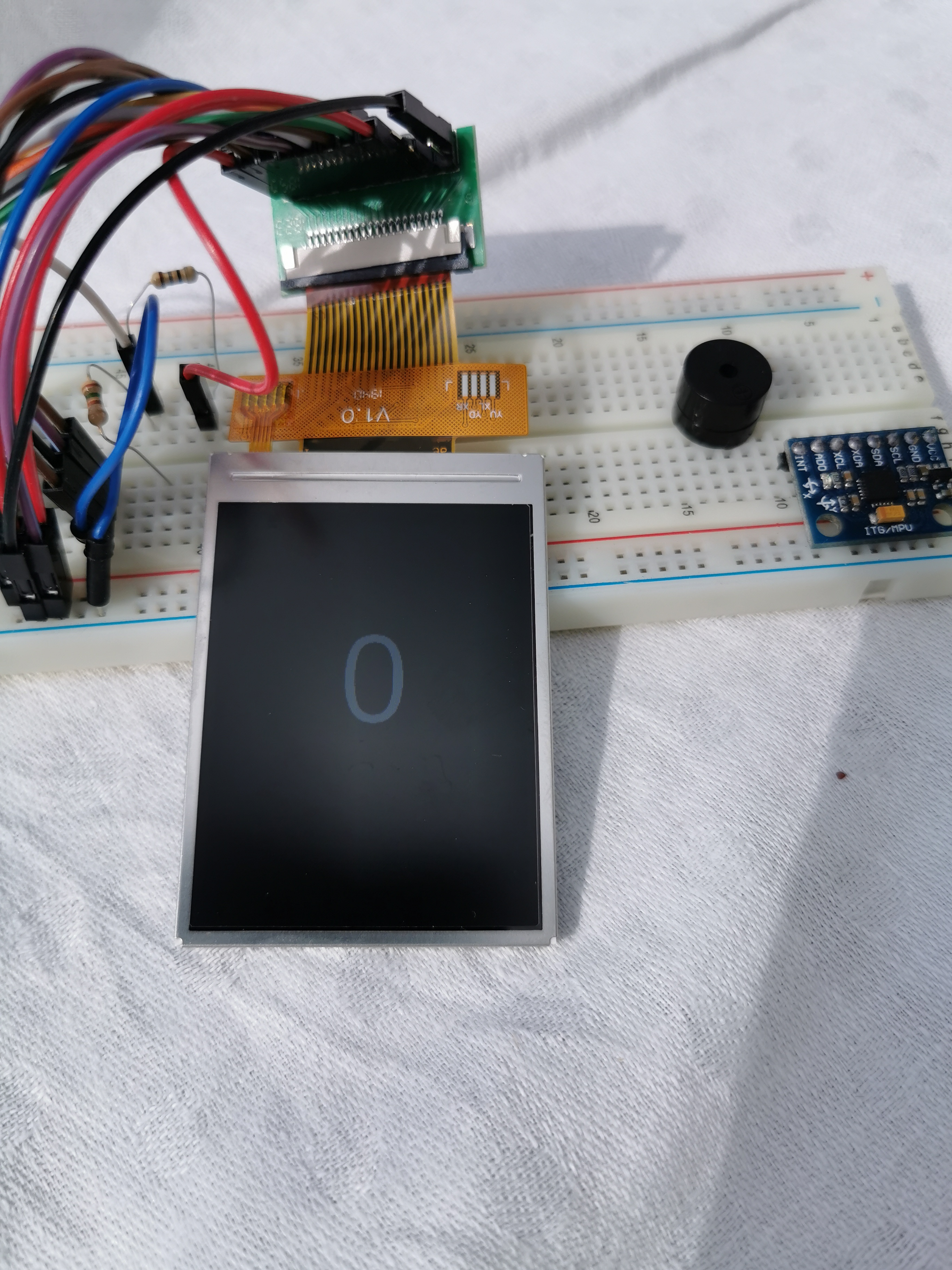
Quite impressive if I may say.
BUT i have also spent a couple of hours on the internet, reading up on TFT displays vs sunlight and have found that there are two (perhaps more) types of TFT displays, the most common one called transmissive (like the cheap AliExpress display and the Newhaven) and then there is tranflective, which is actually using the surrounding light helping the backlight to “light up” the display
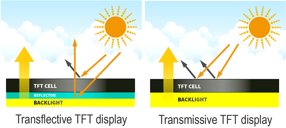
Compare sunlight readable TFT with regular TFT LCD Module

So far I’ve found two candidates.
https://www.displaymodule.com/collections/tft/products/2-0-240x320-transflective-display-panel-spi-mcu-rgb
I will follow up the Newhaven and transflective displays later but right now I have to concentrate to get my foil in the water with what I’ve got, so don’t expect any big results in the near future.
Unfortunately, DHL has estimated the PCB:s to be delivered May 4 ![]() . That means my attention will go to the board and the receiver for the next week.
. That means my attention will go to the board and the receiver for the next week.
3 Likes
I love when the postman knocks on the door. DHL estimated the PCB:s to be delivered on Monday but they came yesterday. 10 new shining PCB:s
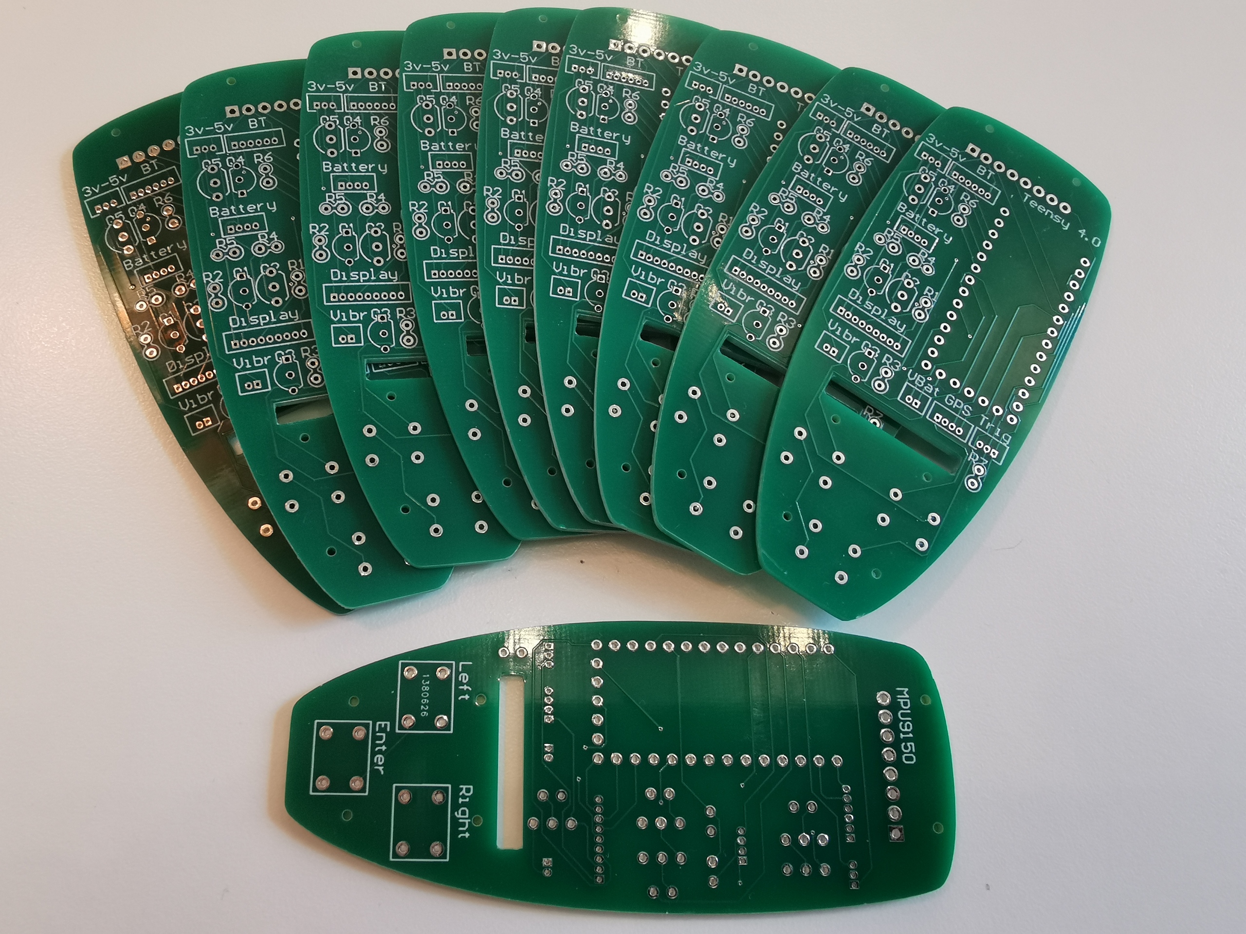
I soldered the components yesterday.
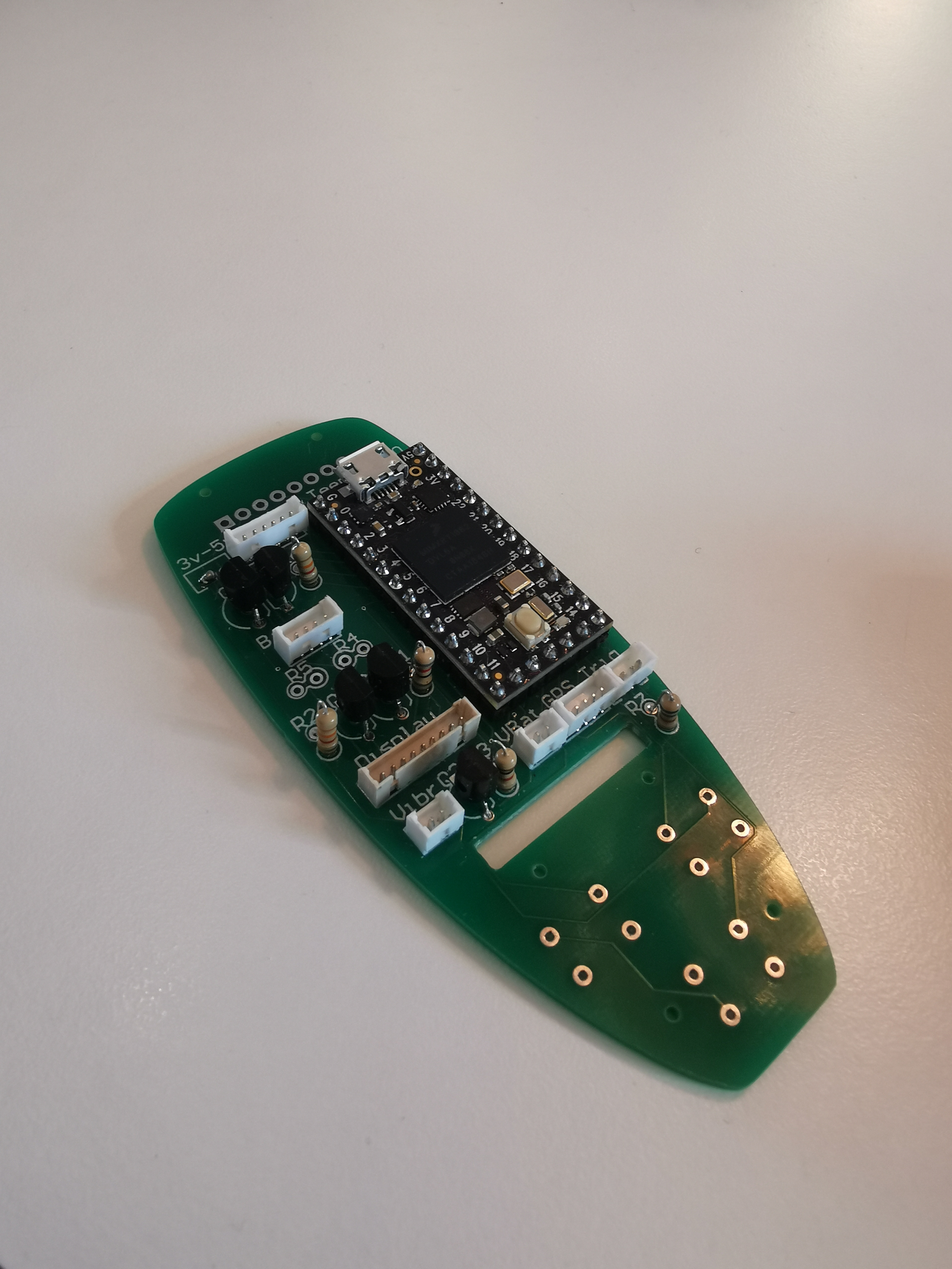
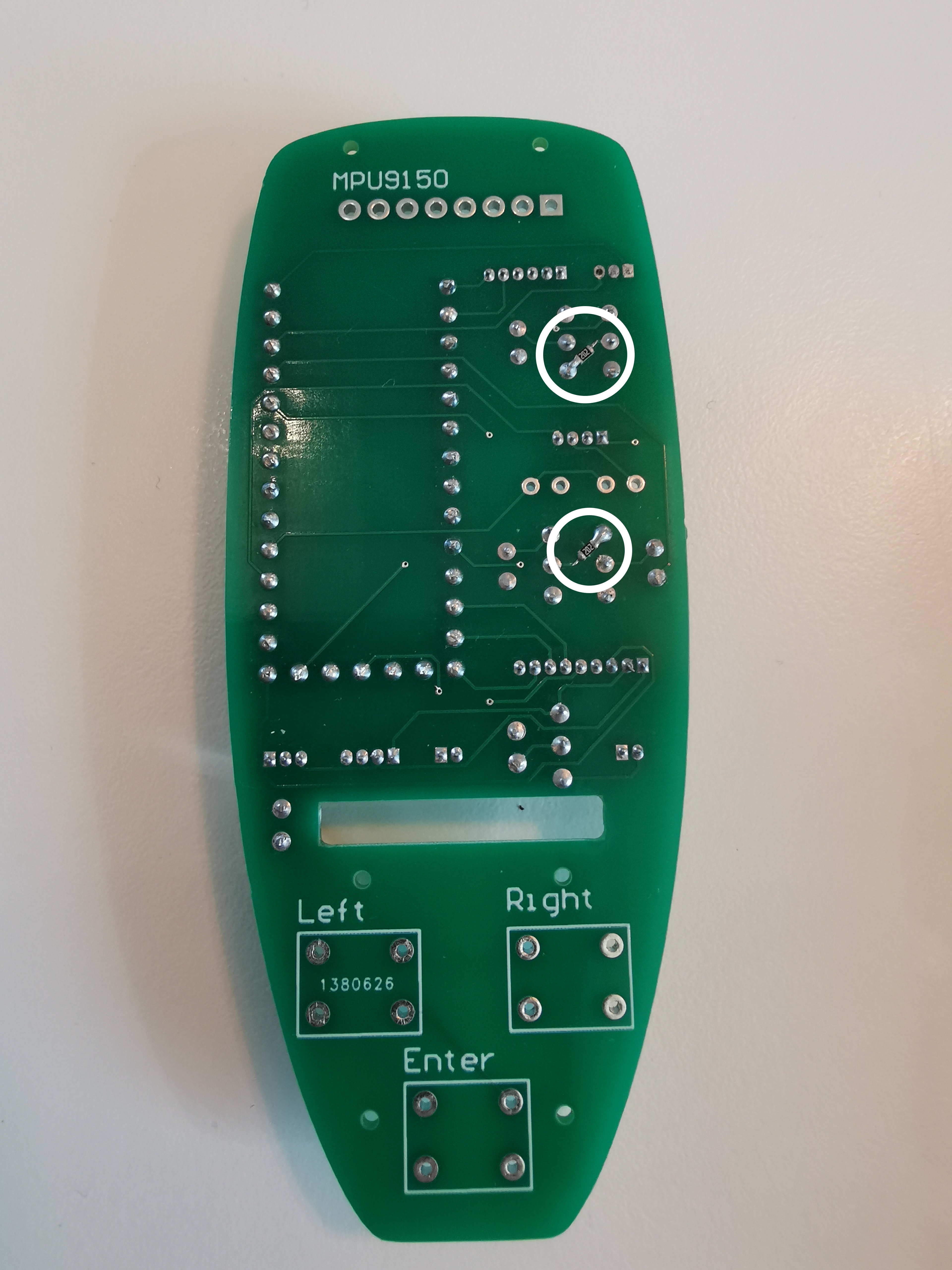
BUT, the idiot designing this (that would be me) forgot to add two resistors, making two of the transistors become burning hot. The resistors are present on the breadboard but It doesn’t matter how many times you review, you always forget something but I’m quite inexperienced at this so I use that as an excuse.
Luckily it’s quite easy to patch, just cutting two lines and add two 2k2 resistors. I have used small smd resistors (which are a bitch to solder) but any resistor can be used, it just looks nicer with the smd:s
So, the display and the bluetooth module works. I will just test the other modules to make sure that the designer idiot has not forgotten anything else and then update the Gerber files and parts list before I order a new set. One other change will be made. The IMU doesn’t fit on the PCB any more due to the backlight. A connector will be added instead
7 Likes
No excuses needed, u are keeping it pretty fuken up! 
1 Like
I’m speechless. Well done! This is just so excellent. Putting an IMU is an interesting design choice. It would not be difficult to train a neural network to learn the pattern in the IMU sensors readings associating with falling/bailing. Use the output neurons of this neural network as inputs for the motor controller system - kill the motor when you fall. I was planning to train a network on IMU data associated with the board (tilting too much is indicative of future failure) however the remote looks like a better point to collect data for this task. Just outstanding work. Keep it going!
1 Like
I forgot to say thank you for sharing this. The Maytech remote is really a bandaid solution for efoil.builders in my mind. It is closed to improvement and will not move the industry along. A project like this being done in the open is a huge step forward for the community. Can’t praise this enough!
Thank you Peter for your kind words. Just want to add, there will be an IMU on the receiver side as well, doing exactly what you planed. This will give a kind of redundant system. If the remote side fails to register a fall, hopefully the receiver side will. The IMU on the receiver side will also make sure that the board is in level before you can start riding, reducing the risk for starting the motor by accident
Great! I read over your initial post and it looks like you had a motor cut planned with IMU data. I would be careful writing code as simple as if (I > threshold || J > threshold || K > threshold). I don’t think we need to train a neural network if we want to be simple but we cannot be so naive as to assume that our riders bail parallel to the X, Y or Z axis! I myself when traveling along j-hat bail with an acceleration vector of -0.5j+2i! Only kidding, I don’t have the data to make that kind of insight about myself yet. My joke was meant to ensure the a threshold is found empirically for the magnitude of the acceleration vector rather than it’s components. I don’t want anyone to get hurt because of an easy to make vector math mistake.
 I have no plans of training a neural network, don’t think the teensy is up to that. I think it will be enough to calculate the linear acceleration from the quaternion on all axis and if the average acceleration of all axis or one axis exeeds a given threshold, we have man over board
void MPU9150::GetLinearAccel(const float* quat, const float* accel, float* linearAccel)
{
    float gravity[3];
    GetGravity(quat, gravity);

    linearAccel[VEC_X] = accel[VEC_X] - gravity[VEC_X];
    linearAccel[VEC_Y] = accel[VEC_Y] - gravity[VEC_Y];
    linearAccel[VEC_Z] = accel[VEC_Z] - gravity[VEC_Z];
}

void MPU9150::GetGravity(const float* quat, float* gravity)
{
    gravity[VEC_X] = 2.f * (quat[QUAT_X] * quat[QUAT_Z] - quat[QUAT_W] * quat[QUAT_Y]);
    gravity[VEC_Y] = 2.f * (quat[QUAT_W] * quat[QUAT_X] + quat[QUAT_Y] * quat[QUAT_Z]);
    gravity[VEC_Z] = quat[QUAT_W] * quat[QUAT_W] - quat[QUAT_X] * quat[QUAT_X] - quat[QUAT_Y] * quat[QUAT_Y] + quat[QUAT_Z] * quat[QUAT_Z];
}Yes the Teensy cannot train a neural network but I was shocked when I learned how simple of hardware can run a neural network. I am student in the Machine Learning class at SCU right now. Once you train a network you have a couple of lists of numbers (weights and biases but names are not important) and these numbers can be thought of as scalars in a big huge long math expression. The training you’re thinking of does like you said require hardware up to the task of matrix multiplication and other stuff. All said, a neural network is overkill if we can get good results with this approach.
I have no real issue with using Y=(X+Y+Z)/3 for setting thresholds because it at least incorporates all terms of Y=X^2+Y^2+Z^2 (formula for magnitude). If you go with the averaging approach please take the absolute values before averaging in case I decide I’d like to be able to bail off both the back and front of the board. The magnitude uses squares to account for negatives.
Best,
Peter
Peter, it really looks like you are into this. Yes, I have already used the absolute values before averaging but I have no problem going for magnitude instead, if you think that is better.
1 Like
Look in the datasheet of the chip most of the modern IMU’s have free fall detections feature built in. But still personally I wouldunt relly on some 50 to couple of hundred hertz latency plus some other latency in transmission and firmware. Yes it will work but in some extreme cases might not work. Like that pro french guy who managed to put his finger in the prop faster than the failsafe.