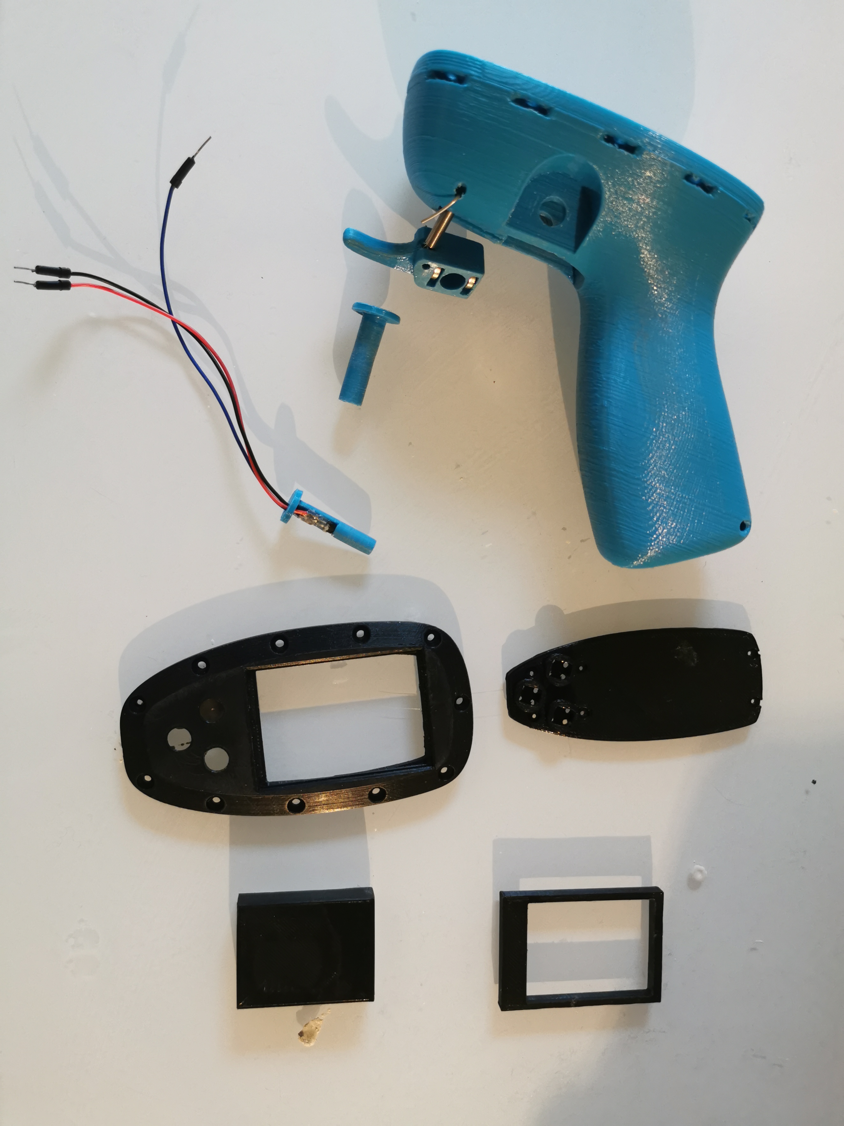
First a big thank you to @Hiorth brothers for the initial design. I have just modified the lid to host some buttons and a larger display.
My box is coming together and I will post an update quite soon but first I’d like to show some progress on the remote control. I have more or less control of all the components involved in the remote. The trigger is stable, the IMU gives me stable acceleration and angles in all directions, buttons are stable, display is showing something, communication to the VESC is stable, I can control the bluetooth unit, it’s waterproof. The battery and charger for the remote are not finished yet.

Brief description of how the remote works
The code runs in a tight loop of 10ms, meaning that one loop with all operations can use more than 10ms to finish. Right now, the longest loop time is about 2.3 ms, so still more than enough time to add more features. But how is it possible to only use 2.3 ms including updating the display? The answer is the Teensy 4.0, and DMA, Direct Memory Access. In short, it’s almost like that the display can be updated in a “separate thread”, also if you look at the benchmarks at Teensy® 4.0, you can see that it is a turbo boosted Arduino on steroids. The IMU is set up to use it’s internal DMP (Digital Motion Processor) to deliver filtered quaternions every 10 ms, so no heavy processing on the Teensy, just calculate the linear acceleration and Yaw, Pitch, Roll (angels) from the quaternions.
The remote has four main states. Startup, Standby, Connected and Running.
In startup, there is just a splash screen showing while the remote is initializing everything. Once everything is done, the state is changed to Standby.
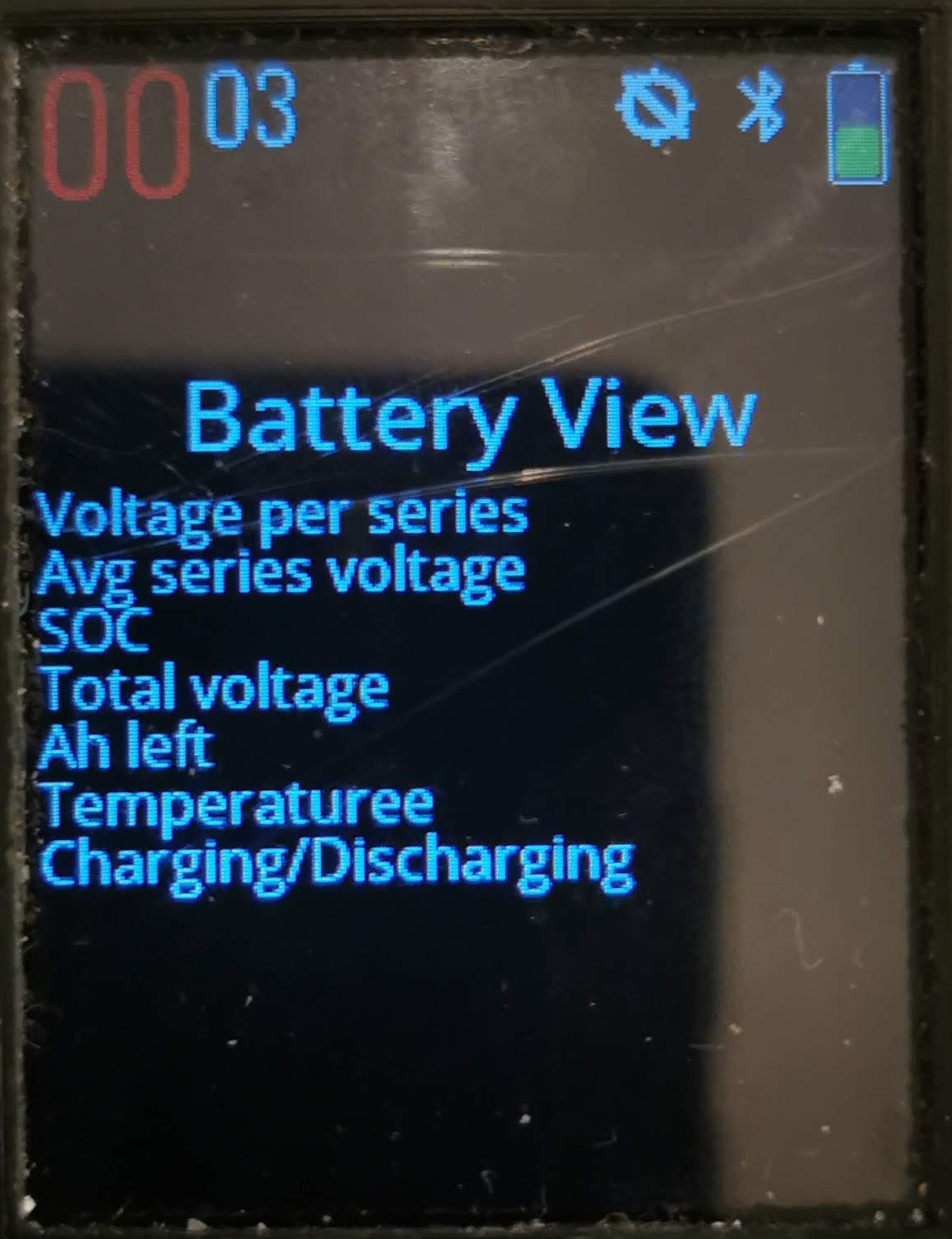
In Standby, the buttons and the menu are available as well as switching between the different views. Every 100 ms, a message is sent over bluetooth to the receiver and checked for a reply. If a reply is received, the state is changed to Connected.
In Connected state, a request for values is sent every 100 ms to the VESC/YAHEF and the reply is parsed and shown on the the different views. Also, the menu option ‘Start Foiling’ is enabled. Once that option is chosen, state changes to Running.
In Running state, the menu is disabled and the remote starts sending trigger values to the VESC/YAHEF as well as requesting values every 100 ms.
Safety
Measure g-force from IMU. If acceleration in any direction is above for example 2G, the remote will stop the motor. The exact acceleration has to be tested out.
Start foiling menu option has to be chosen on the remote.
If trigger is not moved for 30 seconds i running state, the remote will fall back to connected state and no trigger values are sent to the VESC/YAHEF.
The code is no way near finished and I will release the complete code as soon as I can call it an alpha version but I have published a few test projects reflecting the electrical schemas further down.
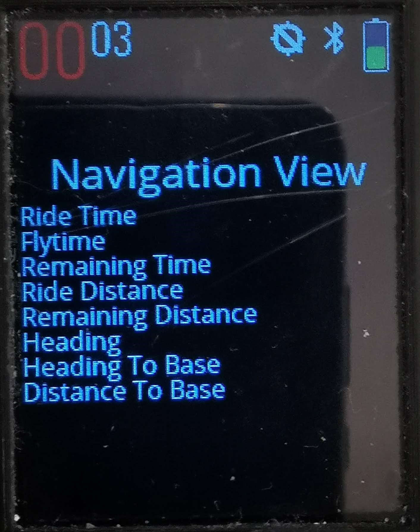
There are more features to come, like cruise control, pop up messages and finish the started views. Perhaps also adding the GPS into the remote as an option, enabling VESC users to track the speed if someone requests that.
PLEASE!! I’m more than happy to get suggestions on either safety improvements or other features, data and views, so please help out…….
I have not built anything in the Arduino IDE therefore I can’t tell if it works in the Arduino IDE. I’m using Visual Studio Community Edition and Visual Micro to develop and build the software. Also the code is written for Teensy 4.0 and I will probably not work for any other devices, but still the code can perhaps be used as reference. In this early stage, the code will contain bugs.
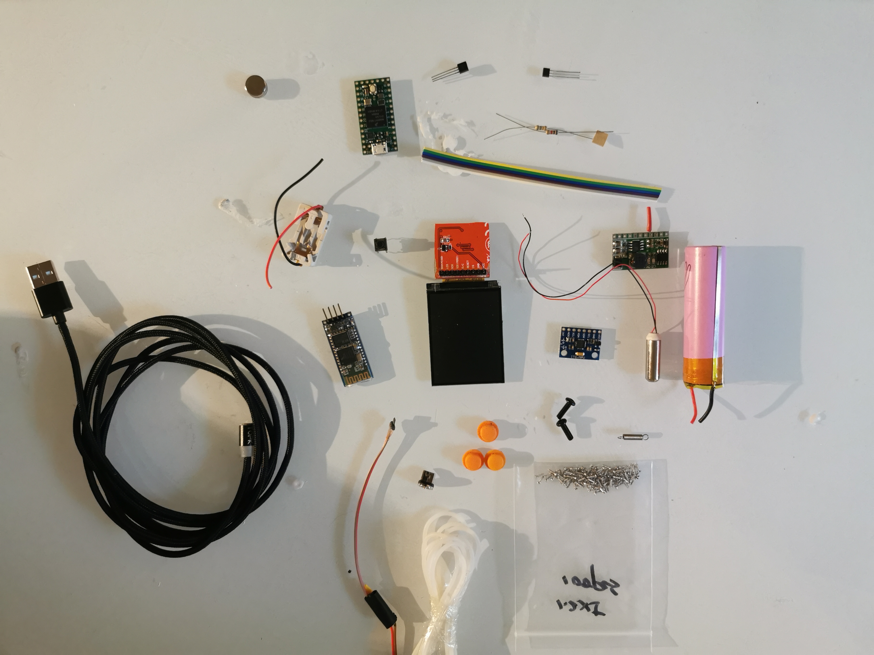
Parts List:
Battery from a portable phone charger from the local hardware store
Charger 5V no pin https://www.aliexpress.com/item/32816412117.html
Magnetic USB Connector https://www.aliexpress.com/item/32827864878.html
Micro USB Connectors https://www.aliexpress.com/item/32708056826.html
Hall Sensor https://www.aliexpress.com/item/32597268764.html
Magnets https://www.aliexpress.com/item/32764112694.html
Spring 20mm https://www.aliexpress.com/item/32863650976.html
JDY-18 Bluetooth Unit https://www.aliexpress.com/item/32888929812.html
MPU9150/6050 Gyro/Accelerometer https://www.aliexpress.com/item/2035920870.html
ILI9341 2.2 Inch Display https://www.aliexpress.com/item/33012793224.html
Tactile Switches 6mm Height https://www.aliexpress.com/item/32857436208.html
Silicone Switch Covers https://www.aliexpress.com/item/32803431368.html
Vibration Motor https://www.aliexpress.com/item/32849172232.html
Teensy 4.0 https://www.pjrc.com/store/teensy40.html
Resistors 100Ohm, 6.4kOhm, 15kOhm, 25KOhm
Transistors NPN2222, PNP3406
Wires
Heatsink tube
Screws M3 x 12mm plus nuts https://www.aliexpress.com/item/32841227345.html
Screws M1.2 x 5mm https://www.aliexpress.com/item/32873583197.html
Seal Ring 78.2mm https://www.aliexpress.com/item/32838978245.html
Acrylic Glass 2mm (Will be replaced by propper glass)
Epoxy Filler
Sand Paper
Spray Paint
In all, I estimate that it takes about 6 - 8 man hours to make the remote and perhaps a week in calendar time with printing, filler curing and paint drying.
,
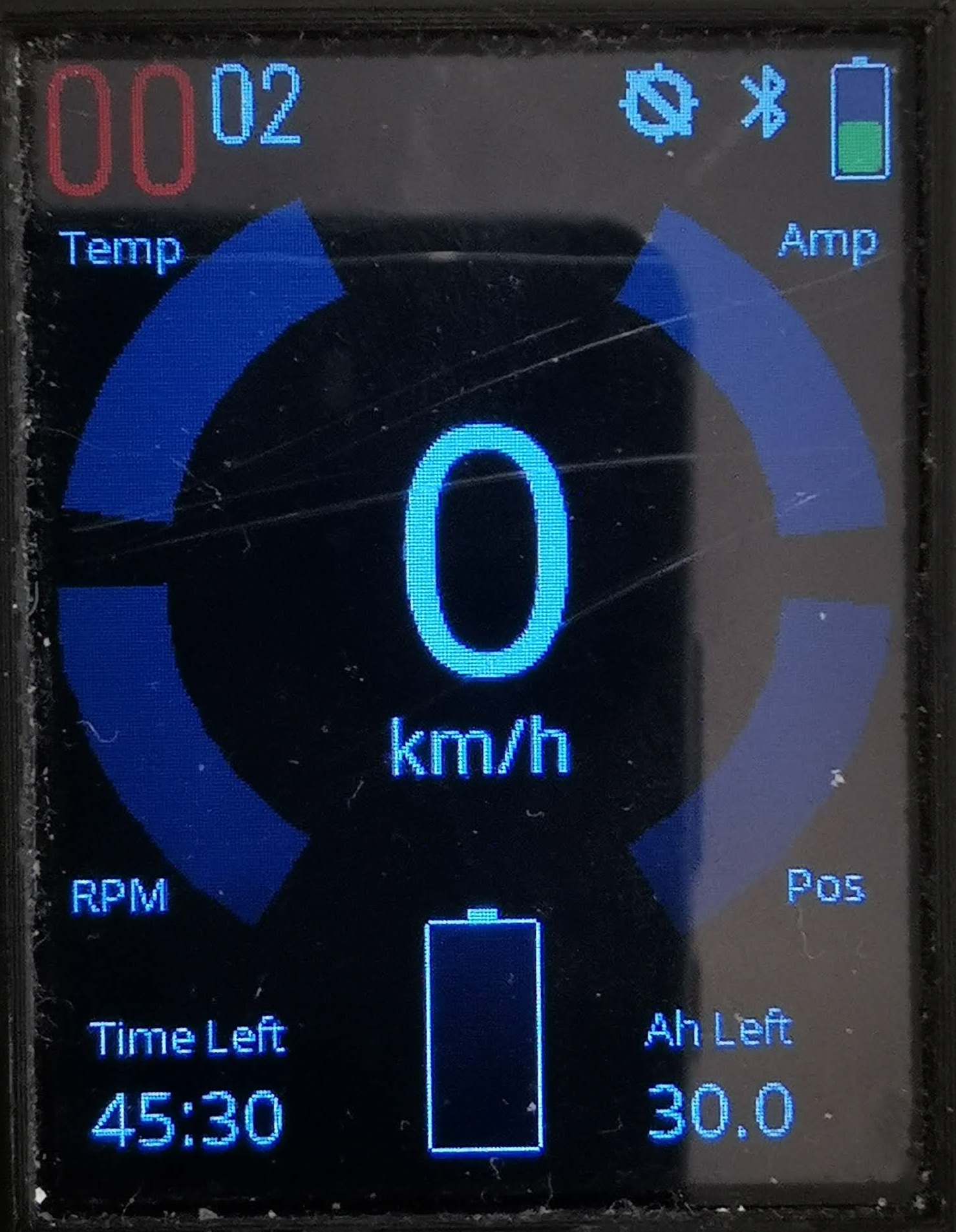
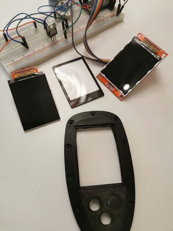
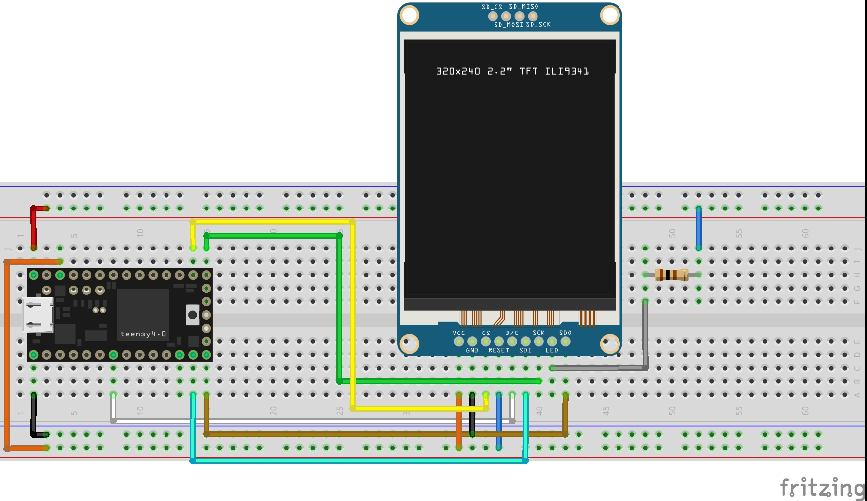
I think most of the parts are self explaining but I think I need to mention a few words about the display. The trick is to peel off the white frame around the display, leaving you with only the display itself and some background plastics and cut the PCB around the pins. Then there is the acrylic glass, painted a black frame making only the pixels visible with help of two 3D printed helper-parts (included in the Fusion 360 link) to center the clear window. The display and the glass then goes into the lid.
Right now there is a birds nest inside the remote. As soon as everything is tested and implemented I will create a PCB
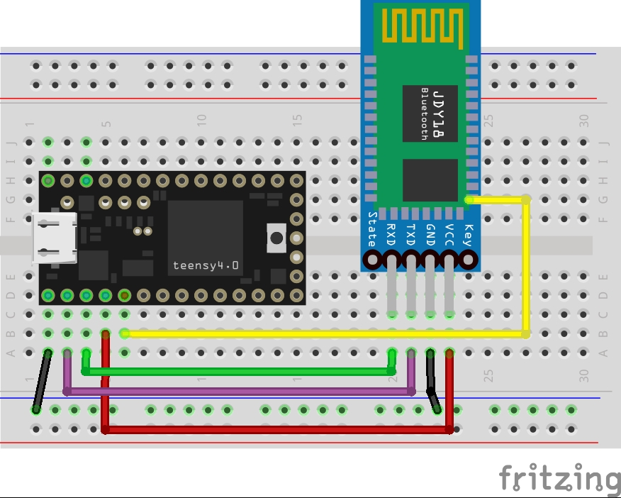
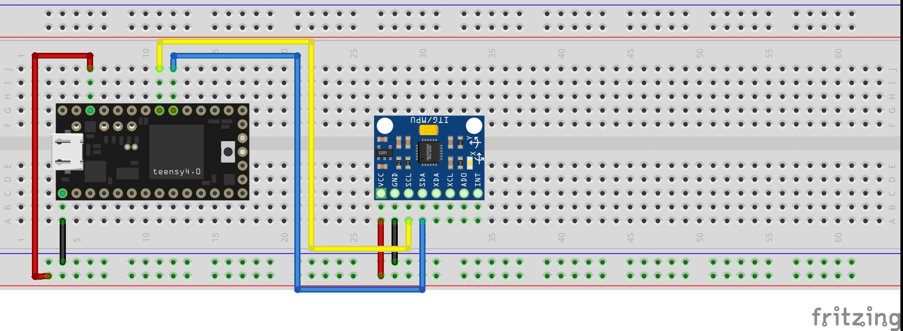
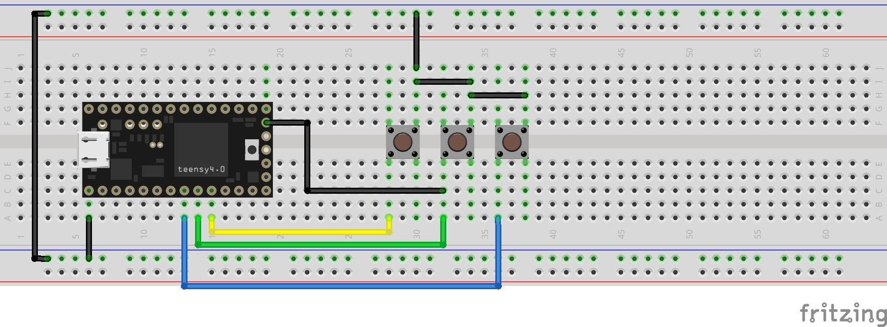
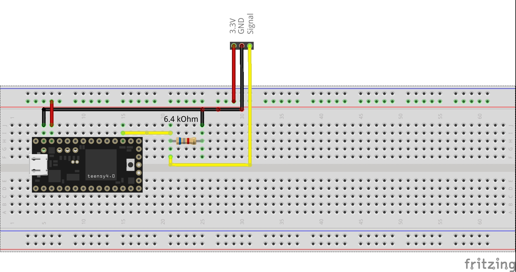
The breadboard images are the different parts broken out from the remote making it easier to follow.
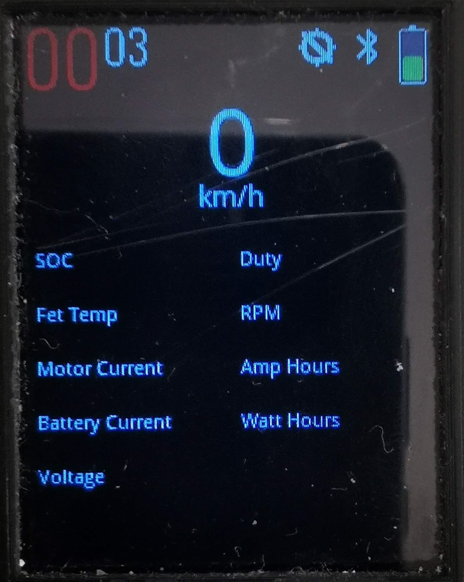
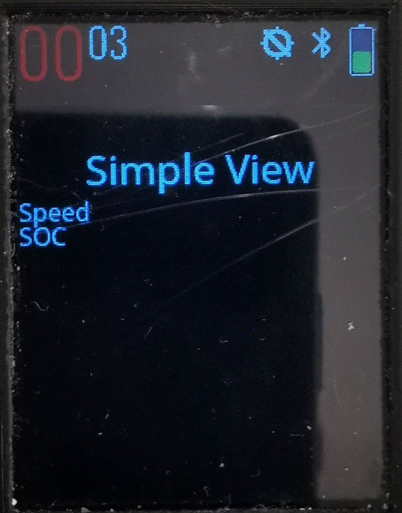
Display
Bluetooth
IMU
Buttons
Trigger
 I love the way you fit that 2.2" display. Have you tested that display under direct sunlight? dattisheet doesn’t mention anything about luminance in the datasheet.