Sorry I went on the website and there are many wrong statements. We are a 25 years old association in a French engineering school based in Grenoble. We are specialised in building electric vehicles, from racing cars, to skateboards, scooters, karts, drones, rc planes… We have our own lab and tools. The efoil project is our first “marine vehicle” project. Back to the subject: the ESC doesn’t regulate the current, but the voltage. That means that as you increase
the throttle, the esc is effectively increasing the voltage delivered to the motor from zero up to the pack voltage, which is full throttle. An ESC can monitor current and have a current cutoff, but it delivers the same voltage for the same throttle imput regardless of the current flow that results. If you want I can make a video proving that the current in the motor phase is lower than the one ine the battery. For that purpose I will use a current clamp.
(video from benjamin vedder, creator of the VESC, took the position control video, because there you have exactly the ~0 movement ~0 batt current and high phase current I described before)
With 25 years of experience I am sure you can tell me why the blue “Current In” (like current from battery) is much lower than the “Current Motor” (like phase current).
While this is being discussed i thougth i learn something (again). What i rember from my university days regarding AC 3 phase systems, winding style changes inline and phase current values. Y winding keeps inline and phase current same. Delta winding caused inline current to be √3 of phase current. (or vice versa) I do realise there were (a)symetrical systems, grounded and non grounded systems or whats the english woord for blue wire etc and totally forgot the effect of it. Super fuzzy memory. What ii was wondering, can this be applied to DC system and does practice actually follow theory? I did have AC and DC motors/generators class but totally forgot since i didnt have interest in motors back then and literature is who know where. I could literally find the page iin 30 sec where transformating formulas were if i could find the book. But…
In my experience Motor current is always higher. Some of the logs from eskate below. Tap the drop down arrow box and only show different stats and you will see the difference ![]()
Damn i love these kinds of graphs. Always had a fetish on detailed telemetry. Thx! I knew something was counterintuitive just couldnt put a finger on it by looking only at some formulas and a blank screen. 
Nice! What setup did you use to produce that beautiful logging graph?
Its the Metr.pro module, made for all VESCs, comes with apps for iOS and Android and webspace for sharing the plots.
I was wondering what you and the Lab have been working on for the past 2 months (since mid Dec 2018) …
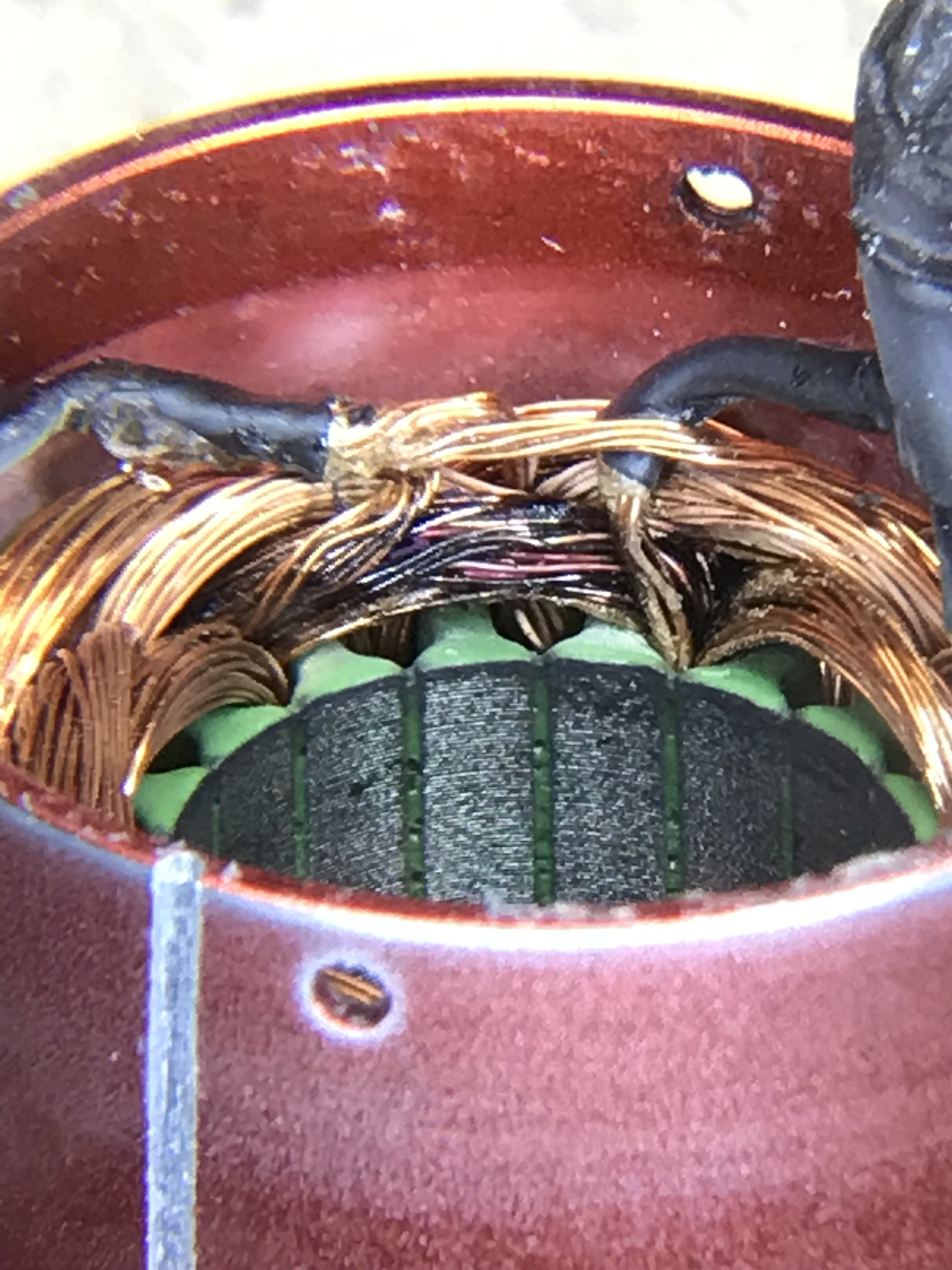
Hi SOEFoil. So I decided last week to disassemble an old esc, a turnigy superbrain esc 100a. I was indeed really intringued by what you said and apparently all the people who gathered data from their vesc’s were saying the same thing.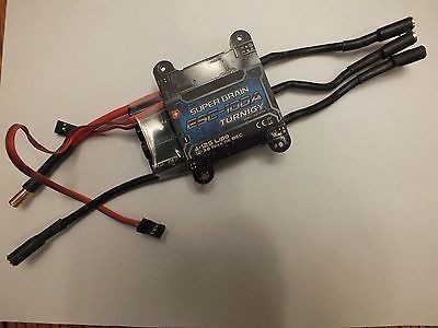 . I myself tested with a current clamp this esc that we mounted on an electric scooter 2 weeks ago.
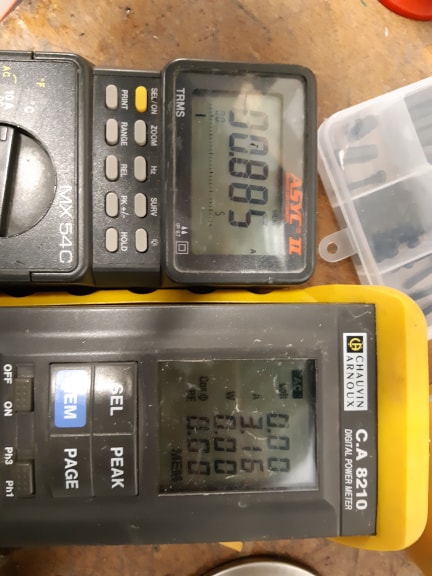
 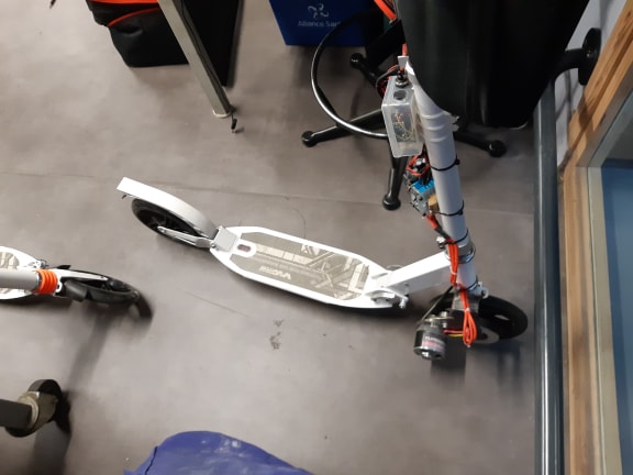 . It was very difficult to find any data on these commercial esc’s but our conclusion is the following : the tension that comes from the battery is first lowered by a dc/dc buck converter ( where you can see the capacitors), and then the mosfets generates a sinusoidal tension as explained in this video : https://www.youtube.com/watch?v=uOQk8SJso6Q. This explains why the RMS value of the current on motor phases we measured is 3.5 times higher than battery current :
Oh noooooo… But why would the copper(enamel wire?) turn Black?
When you push to many amps through a copper wire it will melt.
Just trying to understand why it burned … Is the esc works with any feedback , closed loop? It melted because of high amp for too long and Heat builts up ? Propeller needs to much torque and slowing down to much rpm …
Can this be avoided at the the same demanding torque with a better drive esc ( foc , current control …) ?
The short answer is that I pushed to many amps through the copper windings. The reason for this is because I needed to get more thrust and switched to a bigger prop.
There are many ways of doing this. I knew I was playing with fire but wanted to see the result with my own eyes.
If you do all the math and calculate everything right you will get a similar result without burning anything. I don’t play that way 
For the Amass XT150, did you end up using them? Do they require a resistor soldered in or sinply solder to the cable and plug and play?
I am using them. They are anti-spark connectors so it’s built in.
Sorry, I thought you meant the AS150, I am using those.
So you were totally wrong. I’ve also measured higher phase current than battery current, if an ESC producer has smaller dc wires than phase wires then it’s time to change ESC or update wires…