I remember somewhere in this thread that @pacificmeister you where having trouble with the mast filling with water? But that did not really bother you since you had your svc to battery connection cables nice and sealed with the silicone on both ends. Im no expert at this kind of efoil build nor do I have the funds to attempt it (lord knows I really want to) but I also remember you attempting to have a water cooling system for your svc I believe was the part, and if this suggestion helps at all you could kill two birds with one stone by simply placing your water pump tube down inside the bottom of the mast, running through the mast to the top of the board, and then to your watercooled svc and then a simple exhaust output for the excess water once its passed through the svc cooling system. This would suck excess water out of the mast and utilize it as the water cooling system needed while also having an incoming supply of water into the mast consistently. If you have the system(including the water pump) running until you finish your ride then there should be no water accumulated in the mast.
Hey @Cjwelcome, thanks for your ideas. If I decide to add the water cooling I will add a dedicated intake to ensure consistent water flow. Sucking the water entering the mast is a nice thought but it will start sucking air from the top once the water is out and the pump won’t stay primed. Water in mast is fine right now, there are other important challenges to solve, e.g. I am still riding with ziplocks  . And regarding water cooling, I will keep that on the future to-do pile, not really sure I need it with this setup. Maybe when I try higher amp direct drive setups again… I foiled 20min last night without overheating issues, the bottom aluminum plate was working well.
We are also having success with no watercooling only a heatsink but I suppose a much larger battery would require watercooling when riding for a long time.
How about one of those freezer ice packs for the batteries? Coupled with a fresh silica bag to battle condensation. I worked with them a lot. Those silica perls bind the moisture and make the air as dry as possible. You can re-dry them in the oven.
Anyone else outside of the US having trouble sourcing the shaft seal?
@swarm I got the shaft seals from Allied bearings in Cairns. The guy was more surprized than me that he actually had it in stock.
Thanks mate! Most stuff I’ve been able to use amazon/ebay but wanting quicker gratification!
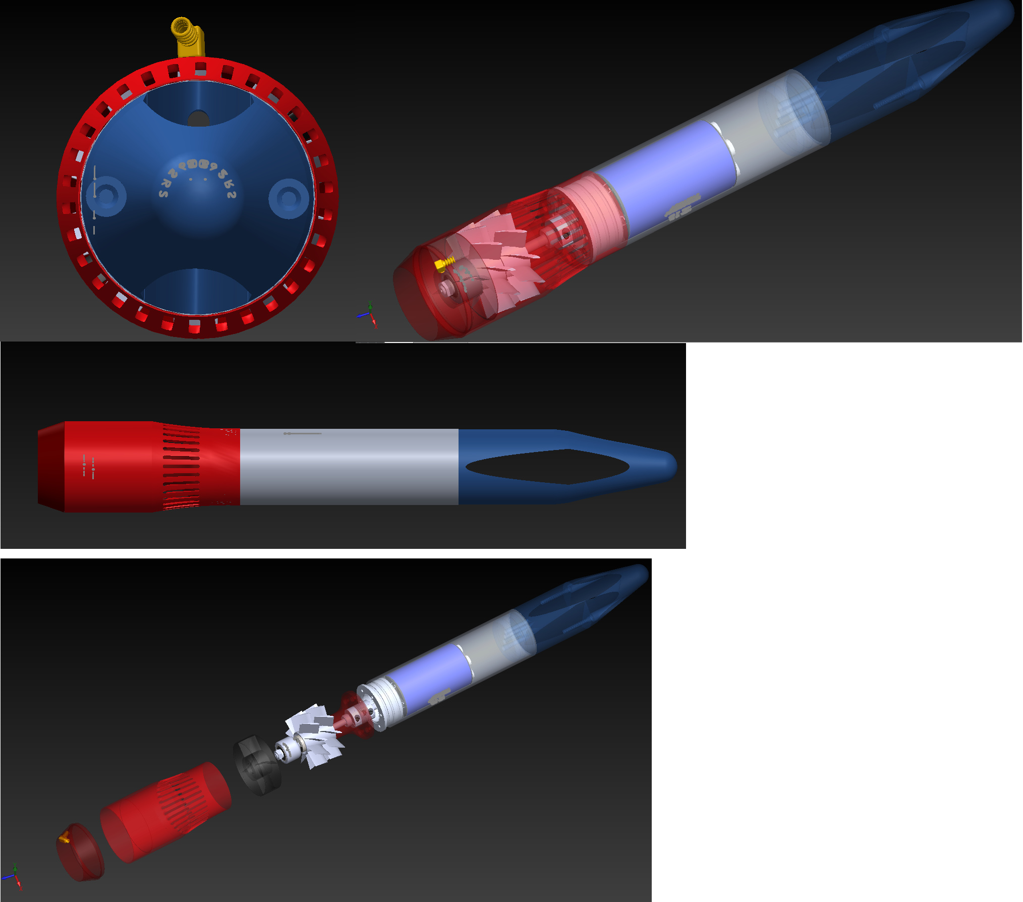
Thought I would share my new design I’m building. here it is in solid works assembly.
sorry have not been here much as I have been busy with other things.
Ant
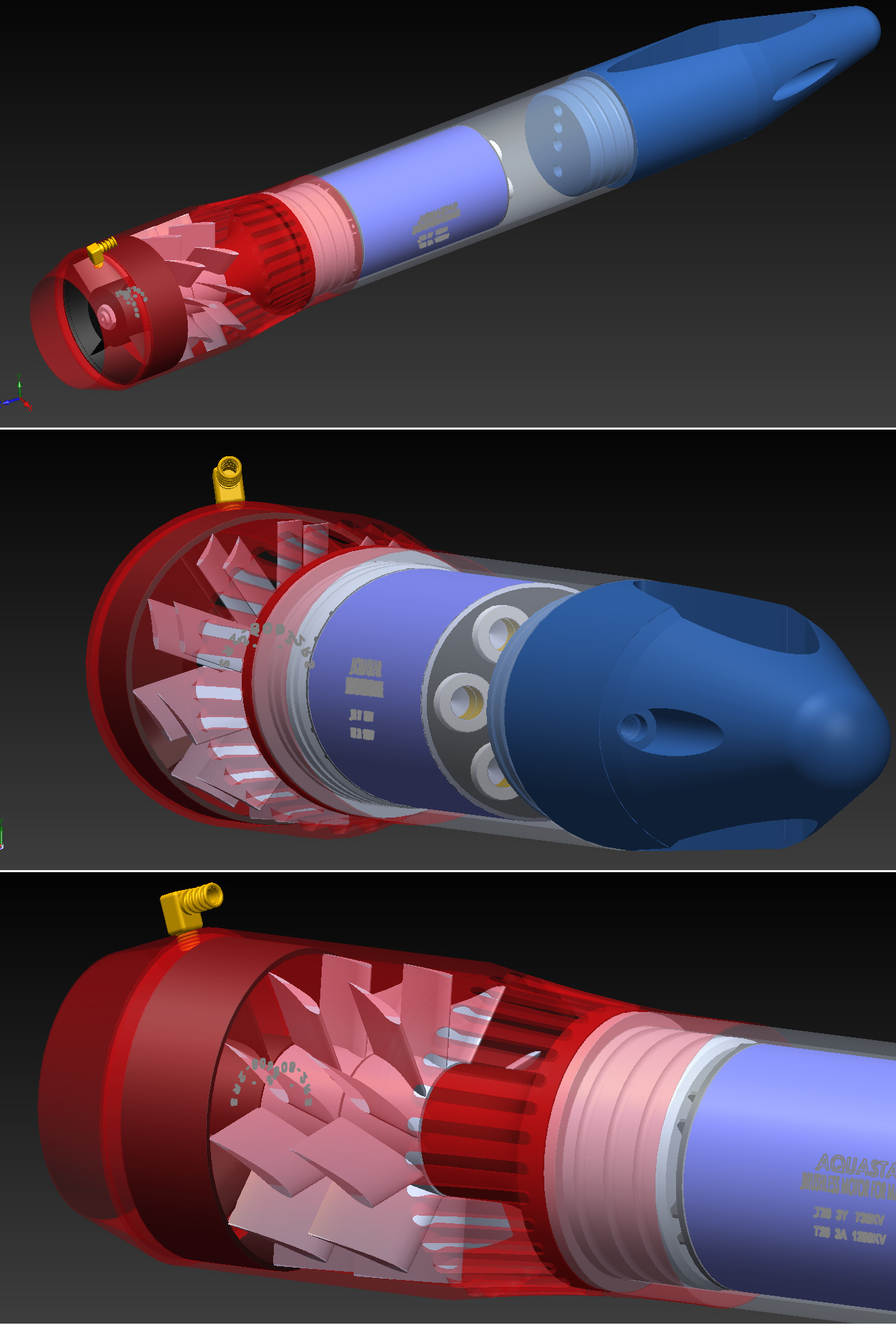
so you got 3 props?
the first 2 (white ones) are connected?
What about the black one?
How do you distribute the power between the props?
The Black one is a stator but looks like you want the opposite Pitch??
@pacificmeister
there was nothing wrong with the stl file (i asked about the measurements a few posts ago).
It was a wrong setting at my printer.
I have another question.
At the moment i am building your build
But i am looking for a custom batterie solution. Can you tell me whats your max current draw at your setup (neugart gear)?
Hello Ant,
Nice pictures and work.
I think that the entry of the water is very very too small and too complex, you will have a lot of loose of efficiency. Look at the difference between the fist version and the final version of the Virus setup.
V1 : exactly the same problem as your design : https://youtu.be/FV1Qgv2K9wI
V4 : with a BIG entry for the water : https://youtu.be/SuKLvpmN-b0
Hi there, thanks for the input, some things you may wish to consider when looking at my model from others.
Take a look at a standard Jet drive intake example below…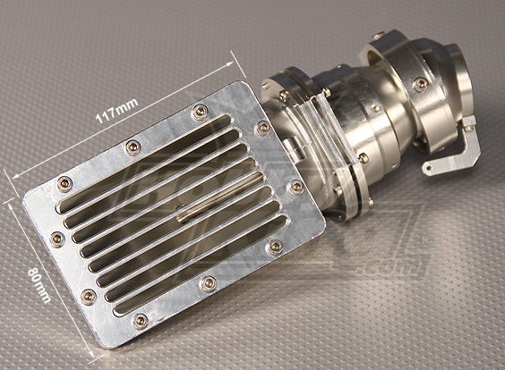
If you calculate the intake surface area, the impeller size and volume of this unit and rotate that surface area from one face as you see here to a 360 degree surface. You will find I have the same water intake surface as a standard unit.
Looks are very deceptive until you do the number.
If anything I could increases the water intake spacing to let even more water in if I needed too.
Yes there is two 70mm impellers, the one in black is not an impeller, it is the bearing housing and ducting support with some aerofoils to uniform the water.
Ideally, two counter rotating impellers would be the best setup ever if the mechanics can be worked out over time.
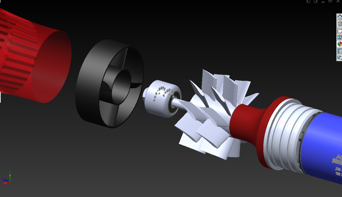
But is it 2 separate impellers, or just one with split blades?
Two impellers as I stated
Hi
Do you have STL files to print it ?
Regards
Giloris
The problem is the number of intakes, not only the surface. Every part breaking the flow of the water reduce the efficiency. 8 big entry on the jet-drive intake, 30 small on your design. It will not work (only my opinion).