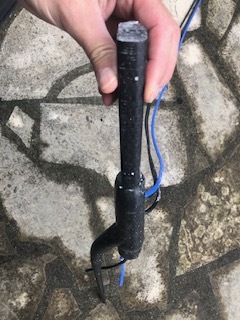
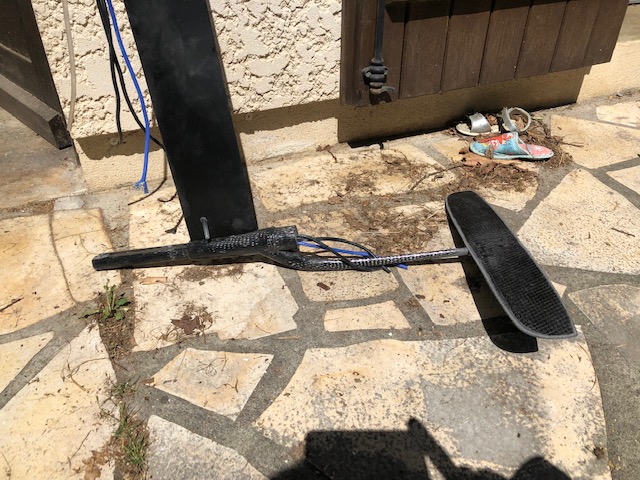
weight (without battery, alu mast included, like on the photo) is 10kg. Inside the board is “classic”. LIPO 12s battery, ESC, some electronics (home made based arduino), water pump. The screw above the mast is mast fixation, i have made a custom insert for this mast (stronger than classic fixation)
volume is about 100l
Like a deep tuttle in windsurfing ? Is it possible to see the board bottom ? The mast outside the board  ?
?
Curious to know how do your motor cables reach the electric box unless you have your ESC on top of the mast … 
Yes that’s a kind of “custom” deep tuttle, i directly fix the mast with screws.
Actually, the ESC is not inside the electric box…i have made a semi waterproof box on the bottom side of the board (close to the big electric box), ESC is fixed in this second “box”. I will connect motor cables inside this box.
I will post photo when i come back home.
1 Like


 Congratulations Fred. IMHO, a page has been turned and you’re about to be massively followed for carbon part making
The traditional set of questions : for how much, printing time of the molds, weight, …
If you have time, would you please show us a few picts of the making process ? 
@visor360 you have a worthy heir/Padawan and tens to come if stiffness is there.
ahahah Thanks SoEFoil! yes of course i will add pict of the molds & process.
Honestly, material cost is about nothing ;=)…and i was surprised because tthe full process does not take so much time about 2h to mold and 2h for cleaning & finishing. If you know epoxy and molding it is not so difficult…everybody can do it.
I have printed the mold with a creality (z max is 50cm) in 4 parts, it takes about 2 days to print (60 microns layers). i have prepared the mold with release agent (not the good one, i have broken the mold)
Carbon about 3m x 10cm, epoxy about 400g.
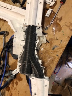
It is my first fuselage in carbon…but i can tell you it is not the last one ;=)
It is super strong, i do not know the final weight, but it is less than my old aluminium prototype…
I am quite happy…when you have it in hands it looks super nice.
I do also wing surfing, it will be easy to unplug the propulsion tube and super easy to test different motors and tube with same foil.


7 Likes
Crazy work. But a good job.
1 Like
Epic! Love the finished product. Looking forward to the pics of the molding and process!
Two remarks:
- there isn’t much room for a duct between a 6" prop (150mm) and the fuselage,
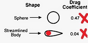
- the fuselage seems to have a round section at its root.This part generates 10 times the drag of a streamlined body of equivalent width (the mast). Therefore, this oblique part is also streamlined on Fliteboard/Hiorth/Evolt design


3 Likes
Good remarks!
-
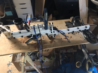
i made several boards with propeller, but this one is for a 62mm impeller
This pic should help to understand the full concept.
-
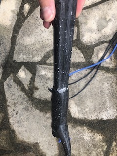
yes the fuselage has a round section, because the tube with the motor has a round section.
By choosing round section for the fuselage i think i reduce the turbulence…because in any case the motor has a round section.
Most important for me, but maybe i am wrong ;=)…this rule concerning the drag coefficient depends on other parameters. Typically it depends on how the object enters in the water and the contact point. If you take a look at a rocket, it has a round section, but the front part is very sharp, and for me it is the most important. How you enter in the water to minimize turbulences.

That’s why the fuselage is not a cylinder but more a sharp cone like a kind of rocket.
And the front wing has to be adapted to fit perfecty with the fuselage shape (to reduce turbulence and help to enter in the water like a ghost ;=) ).
But again, maybe i am wrong…dynamics of fluid class is far far away behind me ;=)
- the arm of the back wing has not a round section because it is not necessary to have one.
I choose a an elliptic shape, maybe this pic can help to understand


My hydrodynamics courses are a bit old too. .
Yes, when a tube enters a fluid along its main axis, a round nose like a half sphere is better than a sharp nose. This is how modern torpedoes and submarines are designed (post ww2 submarine teaching with respect to WW1 ones).
If this tube splits into a second parallel one that moves in the same fluid like here, it is the same issue as a wing on a fuselage. To minimise drag, the transition (in theory) should be streamlined, the round or elliptical section must be hidden in a streamlined airfoil section.
It would be interesting to measure this (supposed) drag penalty by a pulling test with a scale behind a boat or sea scooter at 10, 20, 30 and 40 kmph using a single pulling point. The equivalent load must be balanced so the fuselage must be replicated at 180° on each side of a main tube having same diameter as the motor one.
yeah it makes sense…next version i will modify this transition 


Hi!I would add winglets to the rear wing,this will greatly affect the yaw!
1 Like
Nice work Frederic, happy to see others trying to use 3d printed mold! SoEfoil is right, you could increase efficiency using an airfoil profile. The fuselage is very thin so it may be not stiff enough (depend also on how you laminated the carbon fiber). If the fuselage isn’t stiff, you will have a stability problem (especially with a rear wing this large)
Thanks for the comments Visor! totally agree with you, i plan to add more layers if fuselage is too thin…i will test it…
We start very flat and our front wing uses a low EWD, which means less resistance and less power is required.
Most wings set ups have too much profile thickness and too much EWD to be efficient.
Oh, I’ve learnt a new expression in German:
EWD = Einstellwinkeldifferenz = Difference in angle of incidence (between front wing and stab).
Some people call it “decalage”, “V” or “Vee”.
To get an earlier take-of (low speed = lower amps and power), one can increase the stab leading edge nose down by 1 or 2 degrees:
- adding thickness under the rear screw if stab above the fuselage,
- adding thickness under the front screw if stab below the fuselage.
This operation increases the EWD since the rear angle increases, the front wing AoA being kept constant.
The stab offers more lift downwards so the plane is nosing up and rising more quickly. CON: speed saturation occurs at a lower speed since the stab creates more drag.
To get a higher top speed, people reduce the EWD so the take-of speed is higher (higher take-off current) then the current when flying is lower than with -3degress stab AoA
2 Likes