FLYCOLOR ESC FLYDRAGON-Pro-80A-HV (couldn’t source v2 or v3 which sound better for heat)
Maytech v2 Remote
Wires:
Battery: 10AWG
Motor phase: 12AWG
Connectors:
XT90s (for main battery wires and Y connectors for 2x 6s to make 12s)
Bullet connectors AS150 7mm (for phase wires)
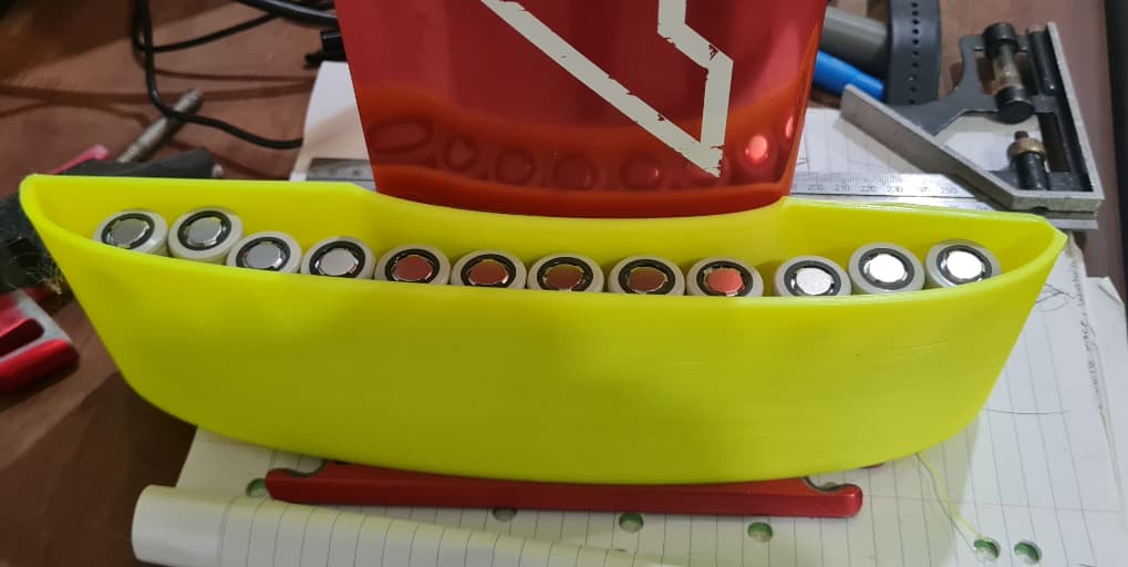
Battery - DIY 21700 12s2p (was going to do 8s3p)
Note making this as 2x 6s (so I can use existing 6s chargers)
Molicel INR21700 P42A cells x 50
Ordered from Huizhou Boot Energy Co., Ltd via Alibaba - Contact Bob Hu
I ordered 50 cells at $2.5USD each. After tax and shipping (& CC fees) landed in Australia at around $7AUD each.
3D Printing Notes
After playing around and doing some test prints… then doing a lot of research, I have learned for max strength…
Increase wall thickness (number of shells), minimum 4 layers (as suggested by @hangloose: No Epoxy. 7 walls and 60% Infill and @V_S : No Epoxy. 6 walls and 66% Infill). Increasing infill does not make nearly the same strength (rarely need to go over 50%, and doing so risks print issues).
Most obvious is use lengthwise prints eg across the bed, as opposed to layers (vertical) along the longest axis (or whichever length needs most strength) - layer adhesion is the issue - which is greatly improved by the following…
Increase layer/extrusion width - either a bigger nozzle or for example (in Cura) Line Width: 210%. The bonus with this is significantly faster prints.
Keep layer height less than 1/2 width of nozzle - in testing for a 0.4mm nozzle a 0.15 layer height was strongest. Bonus is a smoother print.
I found all this info from the amazing youtuber Stefan of CNCKitchen:
I am using an Ender 3 V2 with Cura and using profiles from youtuber CHEP/Filament Friday eg the latest strong print is using his FF5.0_Good (0.2) then applying settings mentioned above (layer height: 0.15, Line Width: 0.84, Infill 60%, Wall Line Count: 7). Also using Tree support type (this is giving me cleaner prints over the standard one)
Some people are using epoxy or other glues to fill in voids - but as mentioned above, others are getting reliable strength without - just good print settings and material.
Got PLA super strong with settings mentioned above. Its so strong I can’t even remotely break/deform the thin propeller blades!
PETG it prints beautifully… but requires specific settings (see below).
Initially I was finding that under stress its seeming to separate on thin parts (prop blade) with compound curves. However solid parts are excellent - very strong. I was discussing these issue over on this post. .
I have finalised my settings for this and it is very strong now - see here
For PETG and PETG-CF - very strong, cannot split walls or layers!:
Temp: 230C
Speed: 50/25mm/s
Flow: 105-115% (default was 95% but this yielded poor wall and layer adhesion)
Layer Height: 1.2-2.0 (1.5 is my pref for looks and strength)
Fan: 20%
Retract 5mm/45mm/s
Apparently FDM is considered useless for waterproofness - so some kind of post- processing eg painting or a coating of epoxy is required. Also avoid sharp corners - so use rounded corners/fillets where possible.
Regarding suitability for use in water - the following is from someone who does 3D printing for a living:
“Petg-cf or nylon would be my recommendation for an efoil. Tpu is very hygroscopic so not great for applications involving water. It’s definitely one of the most durable filaments and could work but may not come out nice with a complex shape that has thin walls”
The following is a reply from BambuLabs when asked which would be their recommendation for our use:
“We would highly recommend you PAHT-CF. Bambu PAHT-CF is a composite of PA12 and carbon fiber. Inheriting the advantages of low water absorption from PA12 and high-performance carbon fiber, Bambu PAHT-CF offers excellent mechanical and thermal properties that can be maintained well even when the prints get wet. Higher Z adhesion layers and flexibility make it ideal for creating engineering parts such as functional prototypes, machining fixtures, injection molds, jigs, and low-volume production parts. But it cost a lot. If you are in a tight budget, PETC-CF, PA-CF are also good choices.”
Other useful resources:
Filaments
The following are invaluable comparisons of filaments and their properties
3D printing - upskilling and planning (see note above)!
2.1 Print out all parts and test them for size and how they fit together, determine what fittings you might need and how you might print them for optimal strength.
Learn about DIY battery building/planning - need to know what size and shape to build.
Design main housing - hoping to go with under-board design - see below.
Decisions/Assumptions (likely to change!)
Have decided on the FD #2 style layout - battery and ESC under board.
I was originally going for FD #1 (on board box) but, due to wanting to use it for proning, lack of space made me consider other configurations like under board (FD #2) or torpedo style like StokeFoil. The latter had many benefits (I think lower drag and having all-in-one unit) but I worry about the leverage of the battery unit and risk of kicking it when wiping out on a wave.
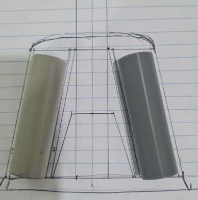
First idea is standing battery cells upright (with mast standing on its base - upside down) on the baseplate - leaning against the mast on a slight ange (due to the base plate fillet).
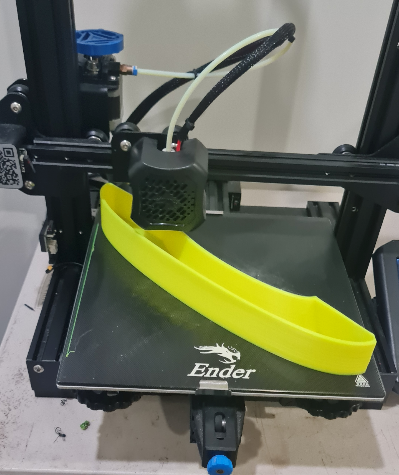
First test 3D model done and printing so I can test how batteries and electric components fit.
Will either have a domed lid (yes will need to add screw placements) or an opening at the rear - this is just a first cut to see how the cells fit and where the ESC and RX can go. I’m thinking in the domed lid (or possibly sit vertically at the rear).
Really pushing the size on the Ender 3 220x220 print bed:
With the ESC in the domed lid it will be very close to the motor and ideal for cooling (will have external heat sink).
RX will have aerial fed out bottom so can be inserted into mast track and covered with foam.
The ESC: can continue the 3d print up to the motor with the esc. Around the esc 3d print material can be aluminum or copper based and so the whole thickness of esc + 3d print will be pretty slim. Or slim radiators incorporated (like these for PC memory and such).
A few questions:
What is the cross-section facing forward of the enclosure at the widest part?
The two halves are glued?
What is the solution to replace battery, because one battery may not be enough for a session?
No, not at all committed to this - just exploring the concept.
My initial model is using 3mm walls all around - my very rapid print prototype is quite weak - but thats more to do with the fast print settings… I have been doing many tests on 3mm x 10x50 rectangles to test print settings for strength… and they are very strong… but that’s for final print as quite slow. But layer separation done concern me… if final print not strong enough, then can strengthen with screws or other means (velcro, cable ties, SS hose clamps or a aluminium strip around it - or fibreglass coating - I’ve thought this would be better laid up as a composite - with a female mould)
The cross section width… I have allowed 1mm clearance from mast and mast base. The walls are 3mm and allowed 23mm width for battery pack - so at top 30mm from mast (19mm Axis mast). At the bottom the base plate flanges out 14mm from the mast at the widest point - so 29+14=43. It’s all very rough estimates and literally lining up batteries on the base plate and eye-balling it.
Only done one side as my printer wont print the whole thing… but, now looking at prototype… think I can shorten it a touch… it might print all in one - if not will have to screw or something else (3m has very strong double sided tape).
Yes, it needs to be able to swap battery packs in/out mid session - either a screw down top or rear end… I think the rear end would be better - that also overcomes the print bed size issue, and I think will be easier to keep water tight… less join surface area (less warping risk).
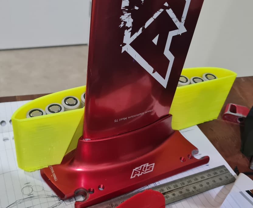
This is 80mm in height… if I add a domed top it wouldnt be much more (I would lower these sides 5-7mm first)
I won’t continue up the mast to support the motor… less is more. Also need prop clearance… a quick google suggests 1/6th prop diameter clearance… prop is 190mm diameter = around 32mm. 32mm + 95 (prop radius/motor center) + 90mm battery housing = 207… from what I’ve read 200 is a good placement for prop height (250 for learning and rough water). so 210ish sounds good to me.
Thanks - oh… I’ve already bought a roll of 8mmx0,15 nickel. Each side (battery pack) is going to be 6s2p (so I can use my existing 6s chargers). Was planning on adding extra layers where load requires it (AFAIK on the serial joins).
I meant for you to add a 3d printed section behind the mast, similar to what people do to hide the cable, but you can put the esc there. I didn’t mean to make the battery shell high.
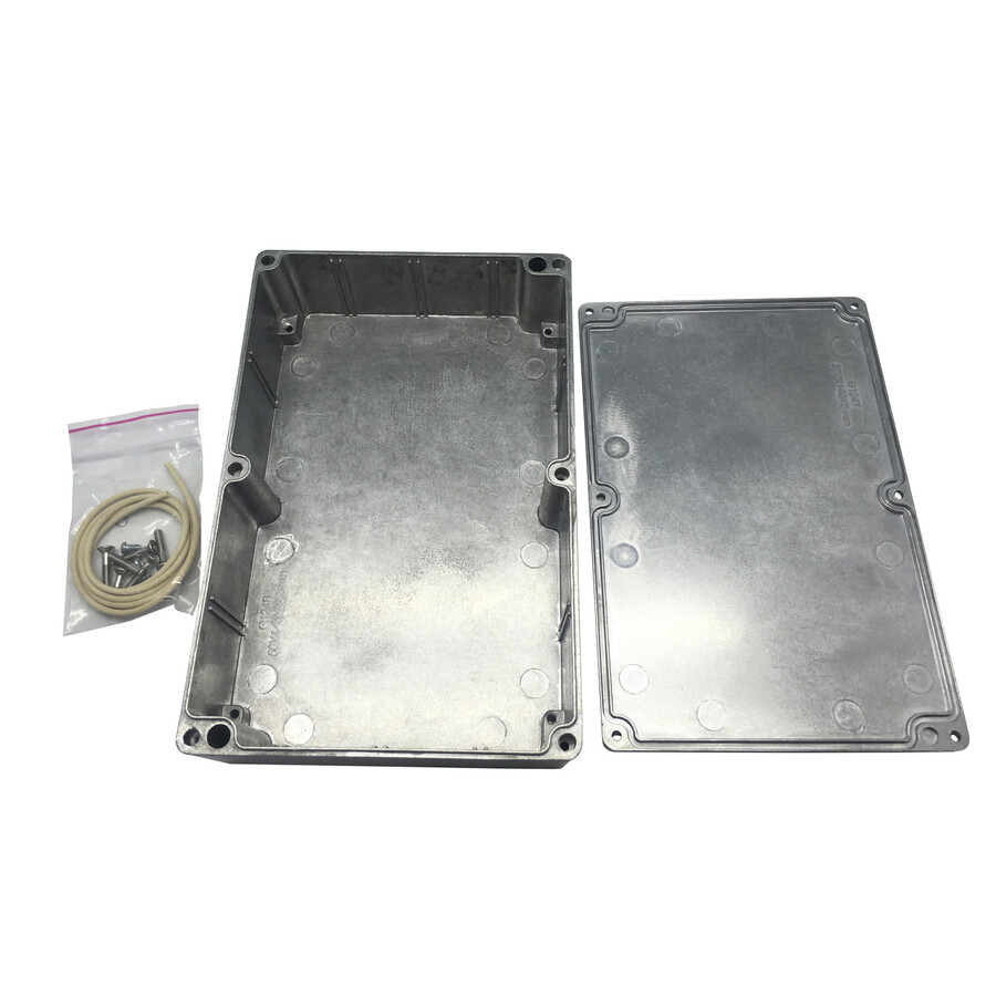
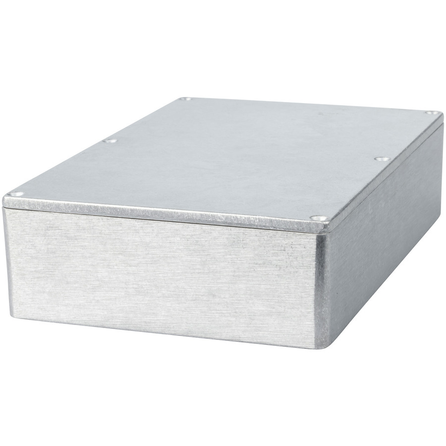
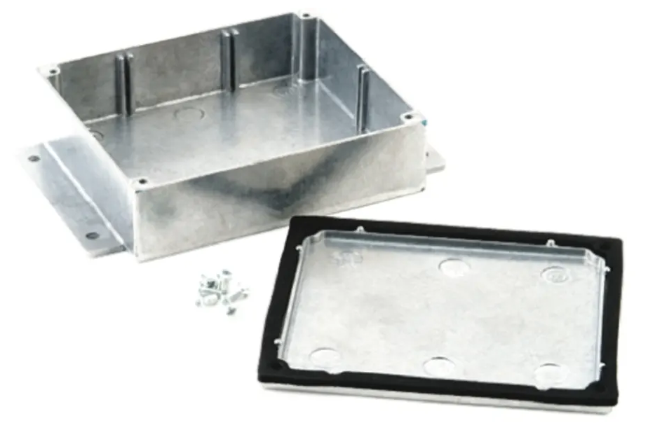
While snooping around at other options for an under-board main battery/ESC box… I found these die cast aluminium terminal boxes… they look almost ideal - except none the perfect size - but pretty close.
Was thinking of using one of these for under the board (between mast base and board like FD#2) but, seeing as most of the them have wall thickness of 1.5mm, not convinced of strength
Another question… about 3D printing… will the heat generated by components, particularly the ESC and maybe batteries, cause integrity issues with 3D printed material (PETG/PETG-CF)?
I was thinking of mounting the ESC in the motor pod with an aluminium lid (screwed onto the 3D printed PETG-CF pod). Being the most underwater component, and, hopefully, always underwater when the ESC is being used, I thought it would be the ideal place for the ESC (for keeping it cool).
I was going to screw on an aluminium plate that was thermal-glued to the ESC. I also considered flipping it - so having the aluminium plate on the inside, against the mast. But on consideration, for a 3D printed object, I think there simply is not enough space around the ESC to deal with the heat.
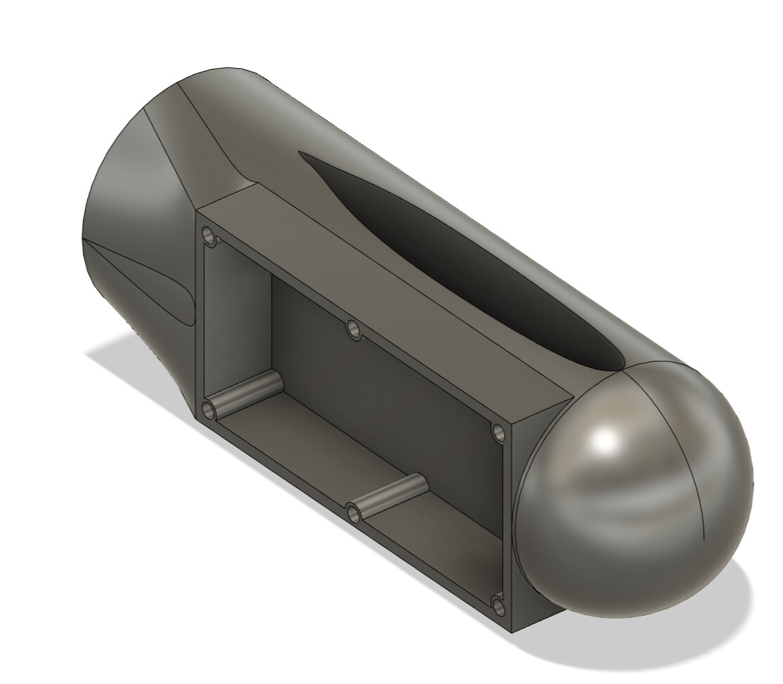
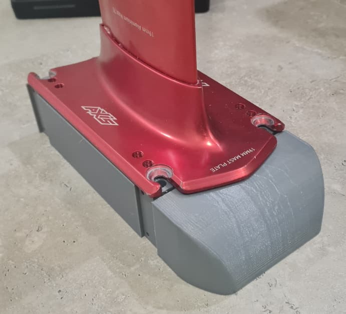
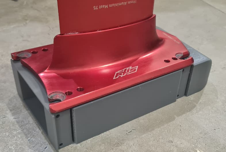
Now going with FD#2 style, I’ve been looking for a 3D printable solution (for the base (under foil base plate - to house electrics and battery)…
First I needed to check the actual print volume of my printer (Ender 3 v2). Specs say it has a print volume of 220x220x250, but testing X/Y proved that it’s more like 219(x) x 210(y) x 250 (z).
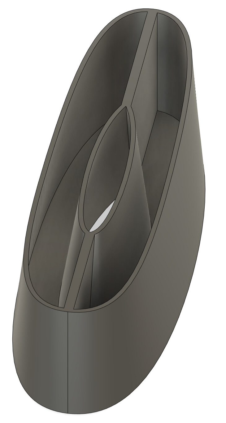
First thought was 3 sections - center to support mast and house battery, front to house and allow to replace battery, and rear for electrics. This mean all parts could be printed flat on print bed.
However, I wanted to simplify this as much as possible… and remove additional parts and in particular, joins.
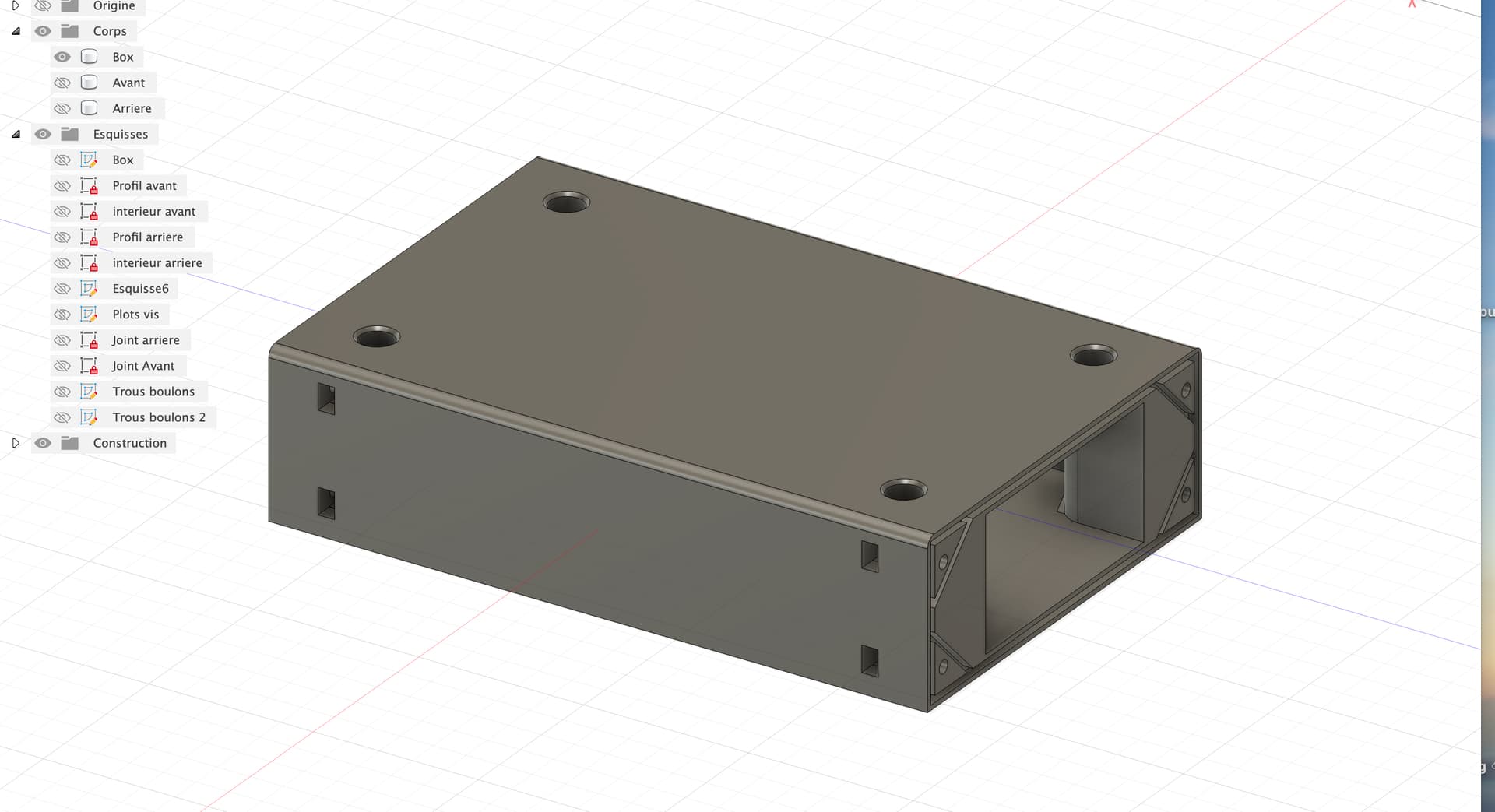
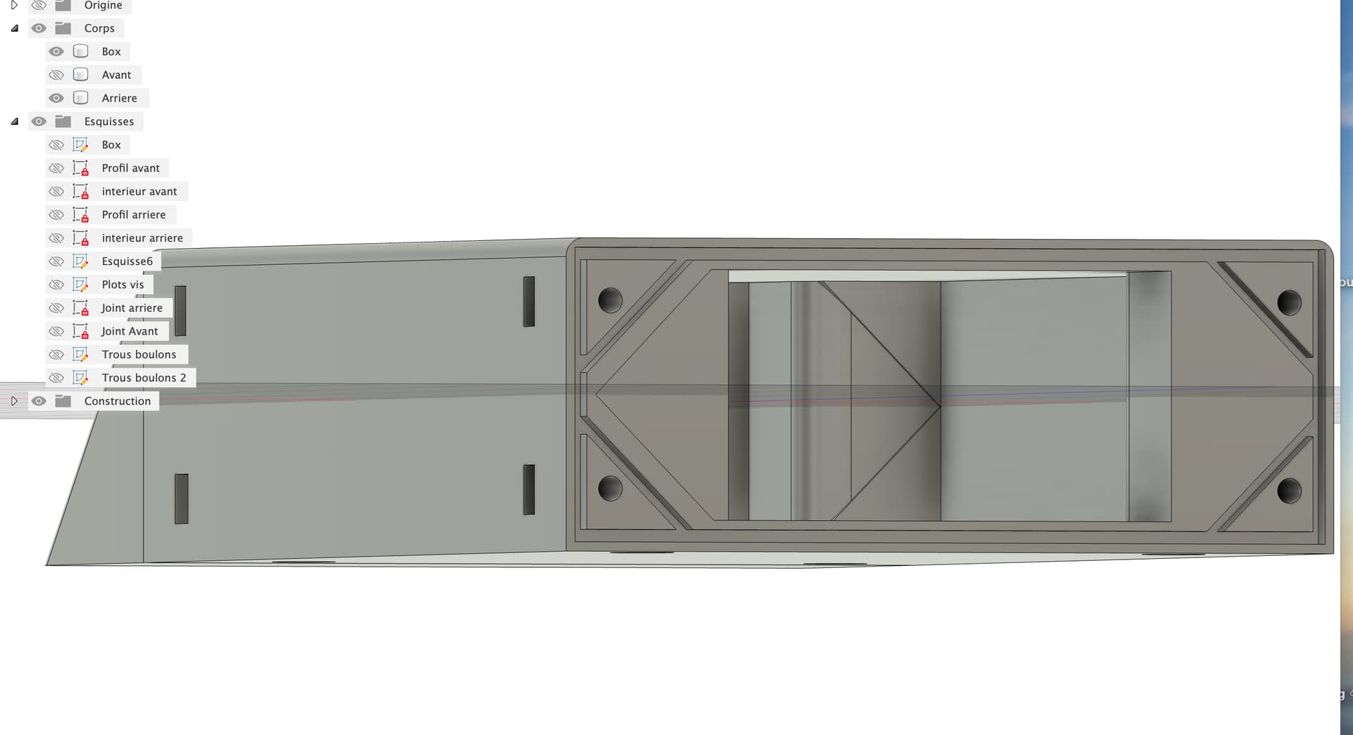
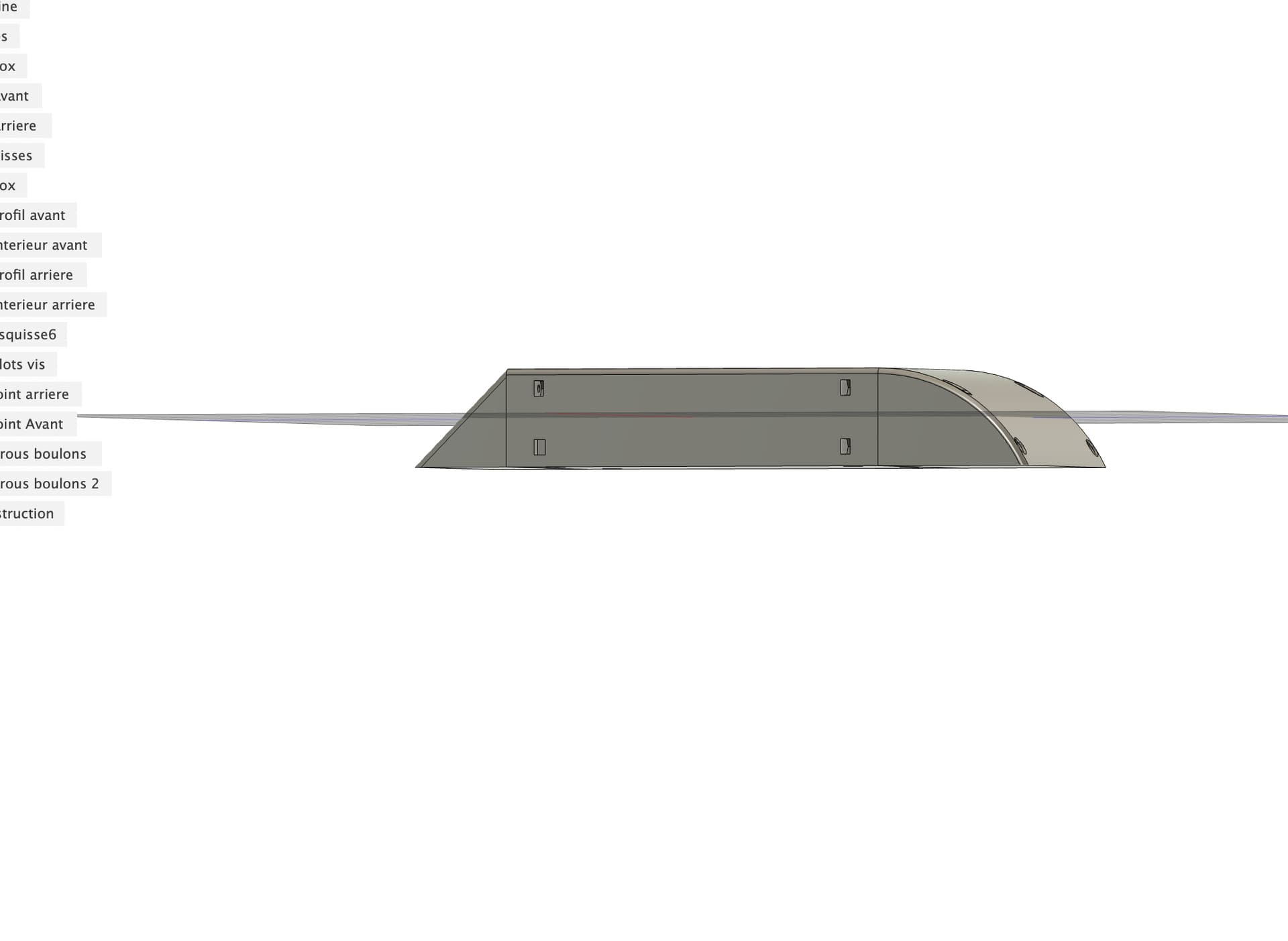
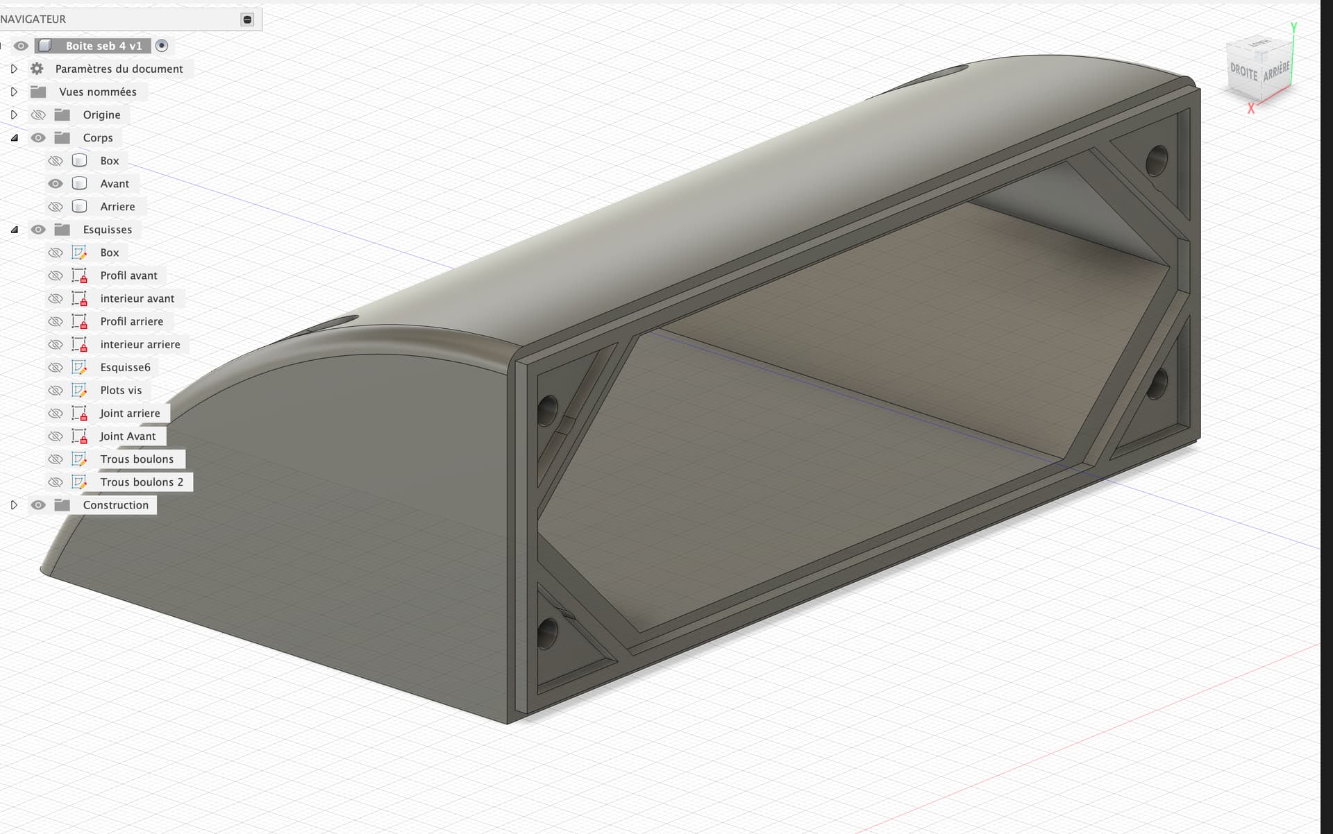
So have come up with a 2 part solution that is printable on my small printer… with a large front part to house the battery and support the mast and a removable rear part to house electronics.
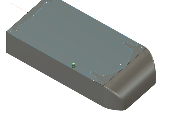
This is what I’ve got so far for the front part. As it maxes out the print volume - will need to be printed upright.
I will make inserts/holes to put vertical aluminium angle around each of the 4 holes for the base plate screws. These will take the load of the screws and weight of rider and allow the use of 3D printed part.
The rear section will have ESC and RX potted with thermal epoxy and will embed sockets for phase and battery wires in epoxy… so fully water proof… with an aluminium plate at the top which the ESC will be thermal pasted onto for heat removal.
Hi, your project is super interesting, I’m also in the process. to try to draw a box to put under the board (I’m new to 3d drawing)
I planned to have a central box in PAHT CF printing with aluminum inserts for the passage of the mast fixing screws.
The rear part will receive the ESC, the BEC and the remote control receiver.
The front part and under the mast will be to receive the 12S2P battery
I’ll post some photos for you and tell me what you think.
Great - your models look really good… and your CAD modelling skills are very good - I have struggled the most with this.
My main issue at the moment is how to do waterproof seals between the parts. I see you have used inset/outsets between the parts - will you also add a seal??
I have also thought that maybe it does not need to be perfectly watertight - as long as the battery itself is sealed and the electronics are sealed (potted) - then it’s only the electrical connectors (battery and phase wires) that need attention - but they can use, like FD, ‘battery grease’.