Ouch, that’s a bit steep!
Well if 18 more people speak up I’d be happy to pay my part, but I’m guessing it’s unlikely  .
.
1 Like
Also, they’d have to make a firmware that would suit all of their ESCs as many of us have different model’s.
Once the initial SW code is written, it is usually costless to spread in the different firmware versions with compilation switches. Then there is the test phase though.
You write the code once, you duplicate it wherever needed.
1 Like
If anyone is looking to upgrade their geared setup from 3D printed plastic to aluminium, I can highly recommend this CNC machined motor pod and prop setup from @jakebarnhill1 The SSS56104 motor and Neugart PLE40 fit straight in, it’s easy to disasemble for servicing and the performance difference from my 3D printed setup is amazing with more speed, longer ride times and everything stays so cool.
It fits my new Gong foil perfectly and i believe it also fits sling shot mast profile too.
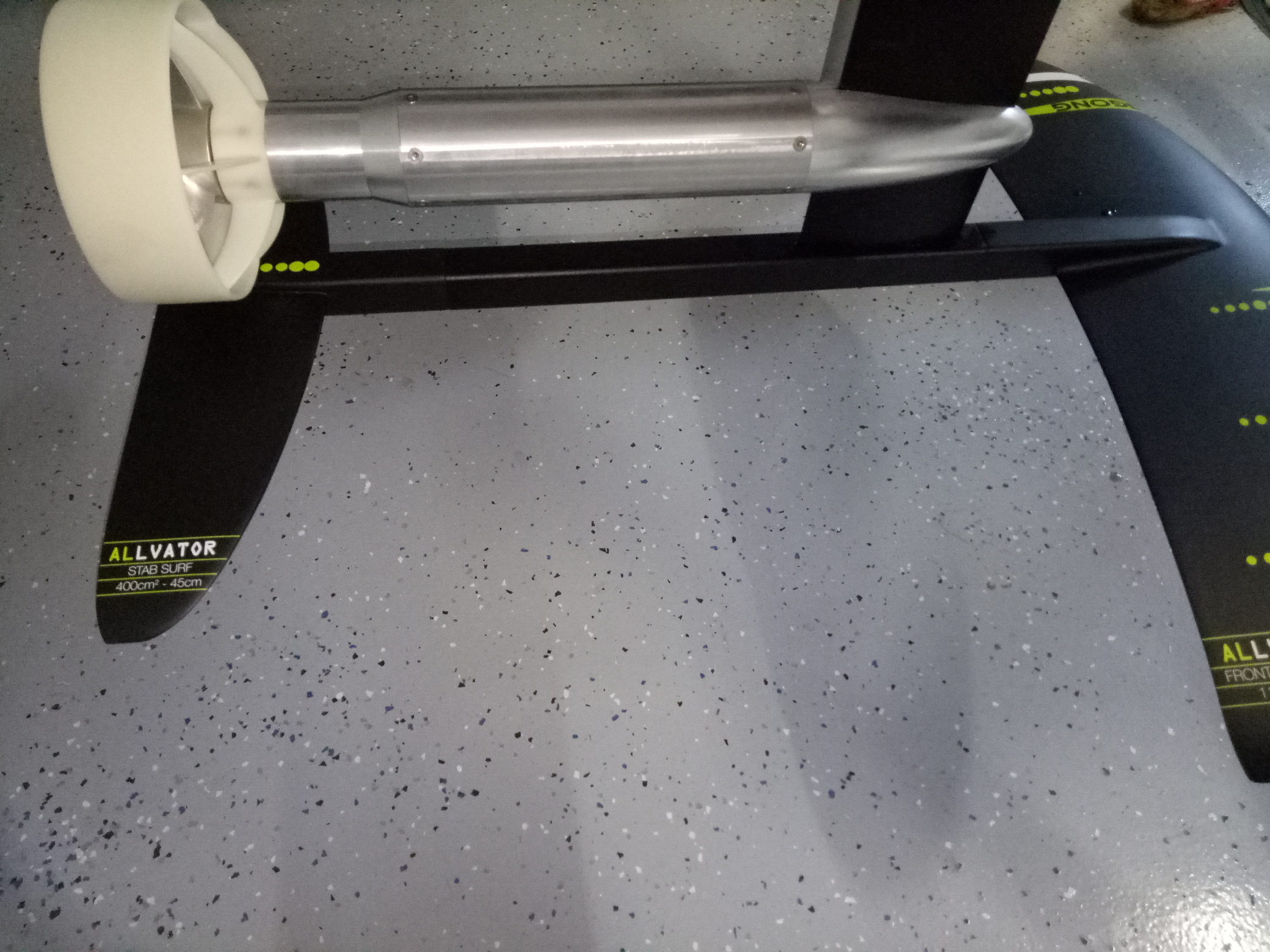
The 3D printed designs from @pacificmeister and @Hiorth are legendary designs that got many of us started but having a solid serviceable motor pod is next level.
6 Likes
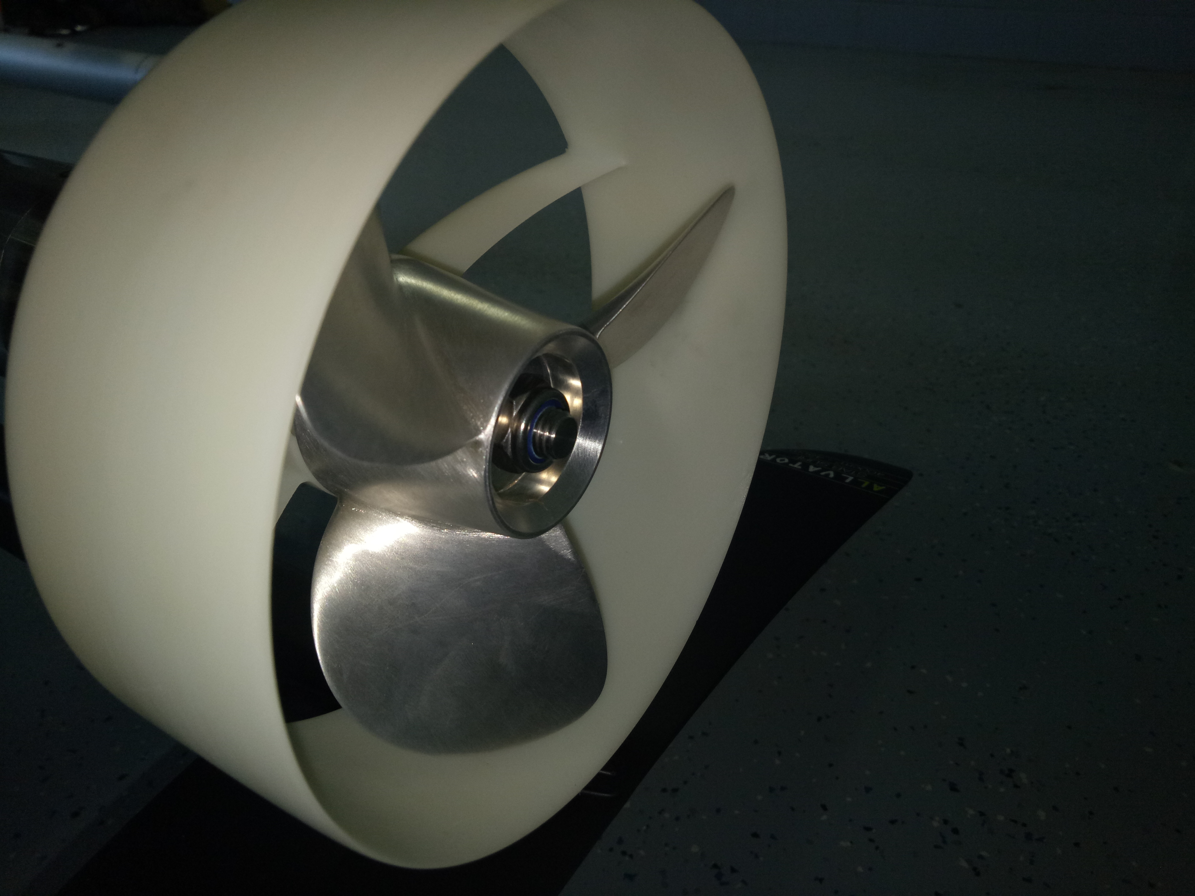
Interested in the prop  . Any cad file or even data ? diameter / pitch ?
Also, since you did not anodize it, I suppose it’s marine alu 5083 ?
It’s a 140mm diameter prop, 217mm pitch. At 4000rpm it gets me 43kmh without a duct and 38 with the duct and about 3900rpm. Its made from 6061-T6 aluminium. Heres a good data video:
5 Likes
Thanks Jake ! Any cad file ? will try it too
Also, you should try alu 7075-t6 with hard anodizing surface finish, that’s what FR / Lift is using
1 Like
That is a fantastic video! Great efficiency. Well done!
1 Like
Very nice build! I don’t know about performances but I can vouch for the smoothness of run of “precision” machined alu pod vs. 3d printed. Also, tight tolerances on seals, O-ring compression, shaft-bearings alignememt make watertight it very easy from both sides (mast and prop), hence the possibility to take it apart.
Wish to be able to cnc my propellers for next build.
2 Likes
I think the biggest changes in performance came from the aluminium prop and thinner duct. The extra speed was easily noticeable.
Combined with my new gong foil and pro M wing, I now have a setup that is more fun to ride than I ever imagined.
2 Likes
Hi. How did you get this nice black line in between the colours Orange and white ?
Hi @Louis I had to tape my board 3 times to paint the 3 colours. It was a bit fiddly and time consuming. Black was the final colour that I used. The get the tight bends in the tape I used electrical installation tape. I found that it stretched around the curves easily. I hope this answers your questions.
I’ve just replaced my ESC with the Flipsky Seal 300 amp. I’m not sure what this little pouch is. Does anybody know?
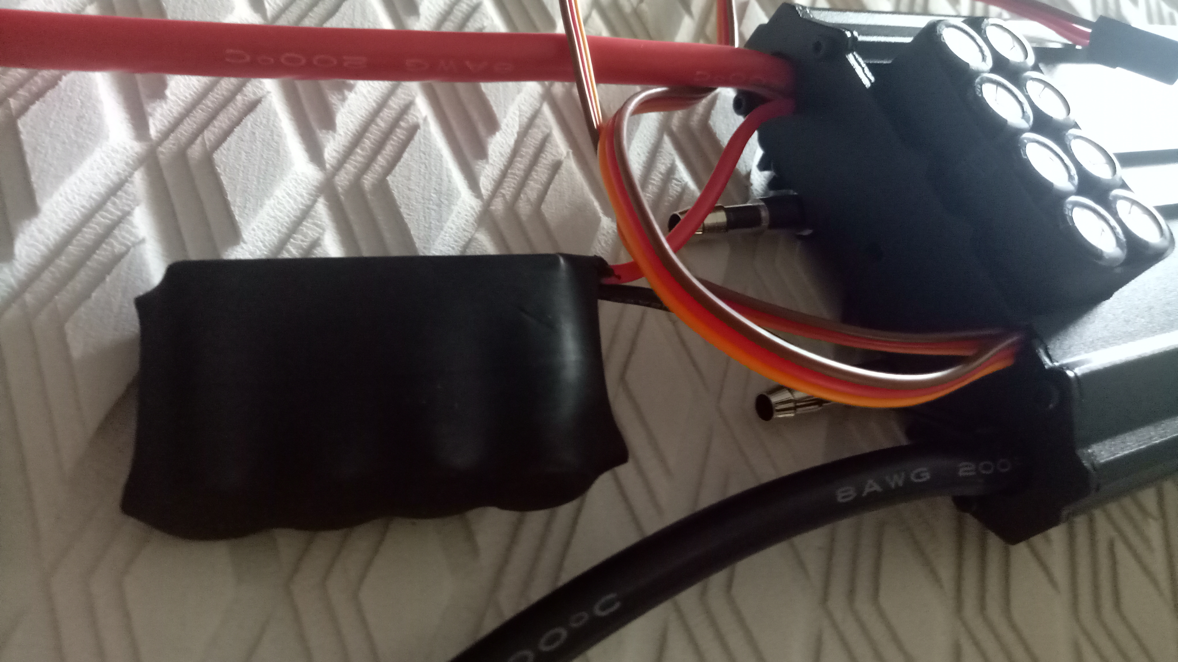
Seems to me like an extra capa bank
Are you sure the data is correct? I assume the current value top left is motor current. And on the bottom you can read battery current.
At 95% duty you have 90A battery and 130A motor current??
Yeah that’s correct. I mentioned that to Benjamin Vedder. He said “The motor and battery current should be quite similar at full modulation if overmodulation is used (kind of going trapezoidal as the modulation goes up), but that’s not implemented in the software. Therefore the battery current will be lower than the motor current”.
I thought the same thing as you, the 2 currents in theory should be closer at 95% duty cycle.
I think it has something to do with how the VESC does FOC motor commutation…
lol, can’t believe vedder said something like that. He should know better than everybody else.
For BLDC you are right: Battery Current = Phasecurrent * dutycycle (neglecting losses)
For FOC you generate a sine wave. Phase current (what is displayed) is the peak of the sinus, so for power comparison you need the RMS phase current.
Taking this into account:
battery current = (phase current * dutycycle ) / (sqrt(2))
Also you are in three phase so you must consider the power factor (phase shift of current and voltage) which depends on the motor. And then you are still neglecting losses (which are in 1-3% range and the VESC doesnt even measure since you got only phase shunts).
3 Likes
interesting, good explanation, that makes sense about why we see different currents! What he said sounded bang on to me. You did see where my speech marks ended in my previous reply?