ASA-X from Dutch filaments is my favorite filament. UV resistant and warping is not as bad as with other ABS based filaments.
1 Like
Thank you for the recommendation!
Excellent. I’ll look into that one. 
ASA prints nice, good looking and long term outdoor capable! Not brittle but interlayer bonding ain’t that strong, so depending from the part you print, could be ok
Thanks for the info.
How would you say the strength compares to other filaments like ABS, PLA, and nylon?
Is layer adhesion strength a common weakness, or could this have been due to your printers limitations?
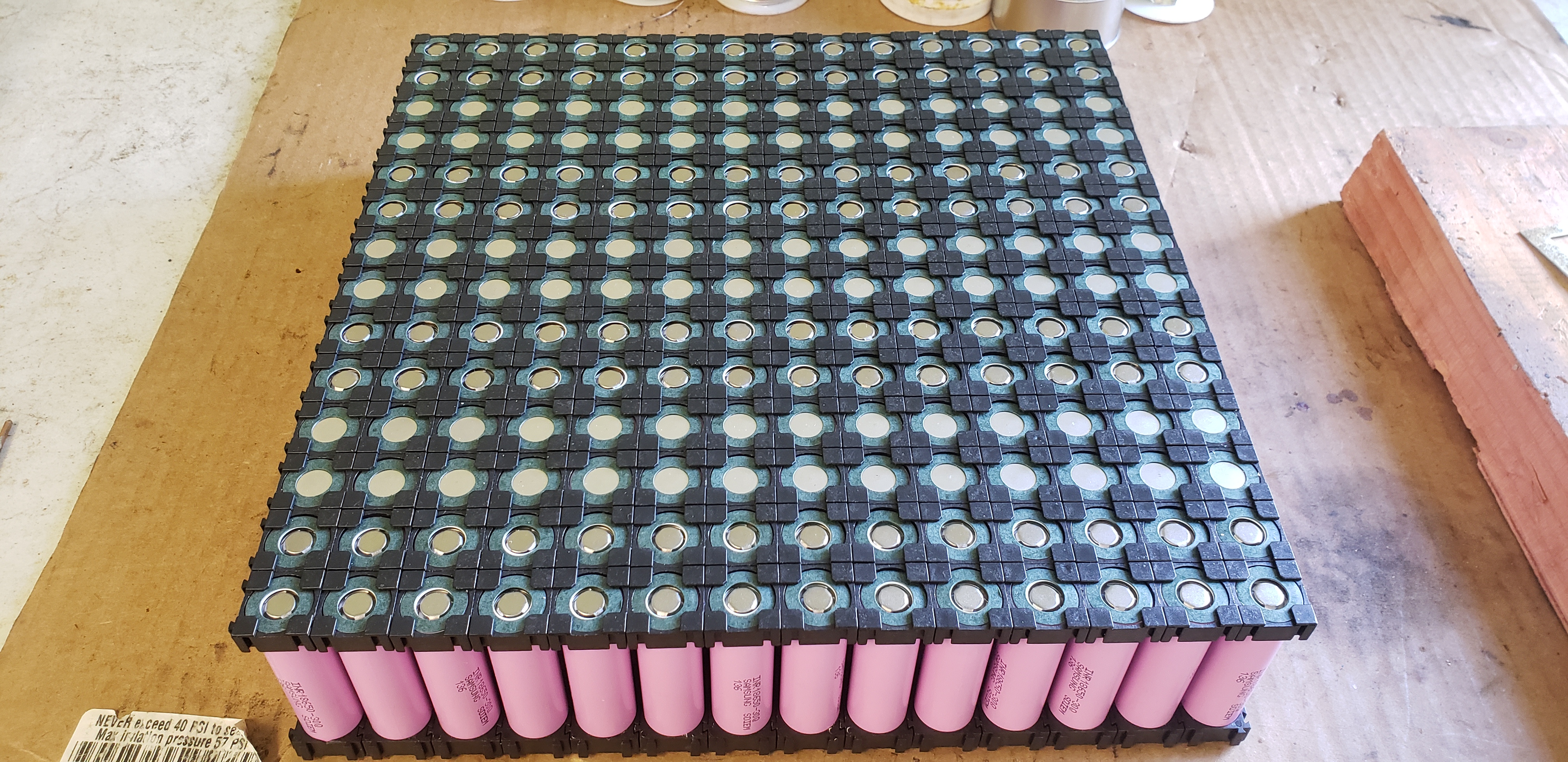
These pics were posted in my other build thread. Re posted here to keep this thread updated.
Complete battery.

It’s a tight fit.
4 Likes
Strength is like ABS, less brittle and more resistant to heat than PLA. Nylon is stronger but much harder to print.
Don’t get me wrong, Asa is as good as the best ABS without odor, UV weakness and also with less shrinkage problems. For parts subjected to compression and hit is fantastic, for something that must withstand bending forces or pull on the Z axis direction (wish to be understandable), e.g. a propeller, a surf fin…ASA like ABS might not be the choice.
PC or even PLA if heat is not an issue outperform ASA for such application. PETG could be a good compromise even thought have more adesion problem with epoxy and other glues.
Nailing the right setting on your 3d printer is mandatory. For PC and big parts in ASA I had to enclose my Craftbot plus in a box, all metal hotend reaches 300 C but the semi-enclosure don’t ensure a warp free result all the times.
My efoil 1.0 and 1.1 were made in PC Max, no problem at all. Last year I moved to aluminium and the 2020 will also be all metal, but propellers are still in PC Max.
5 Likes
hi, do i understand correctly ? does your battery box weight 10kg ? 
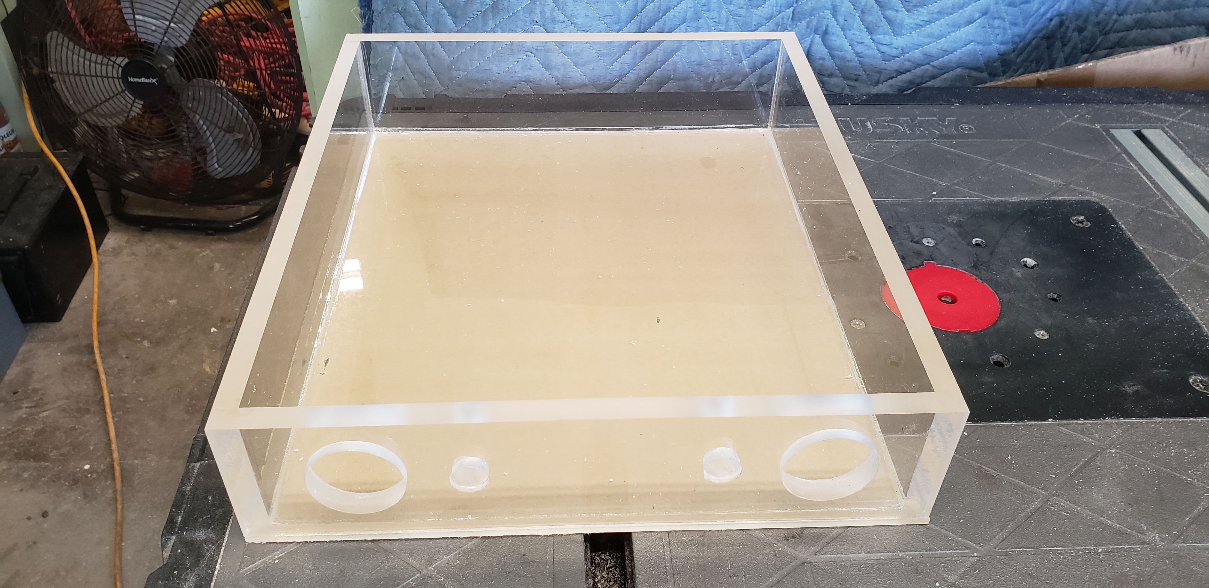
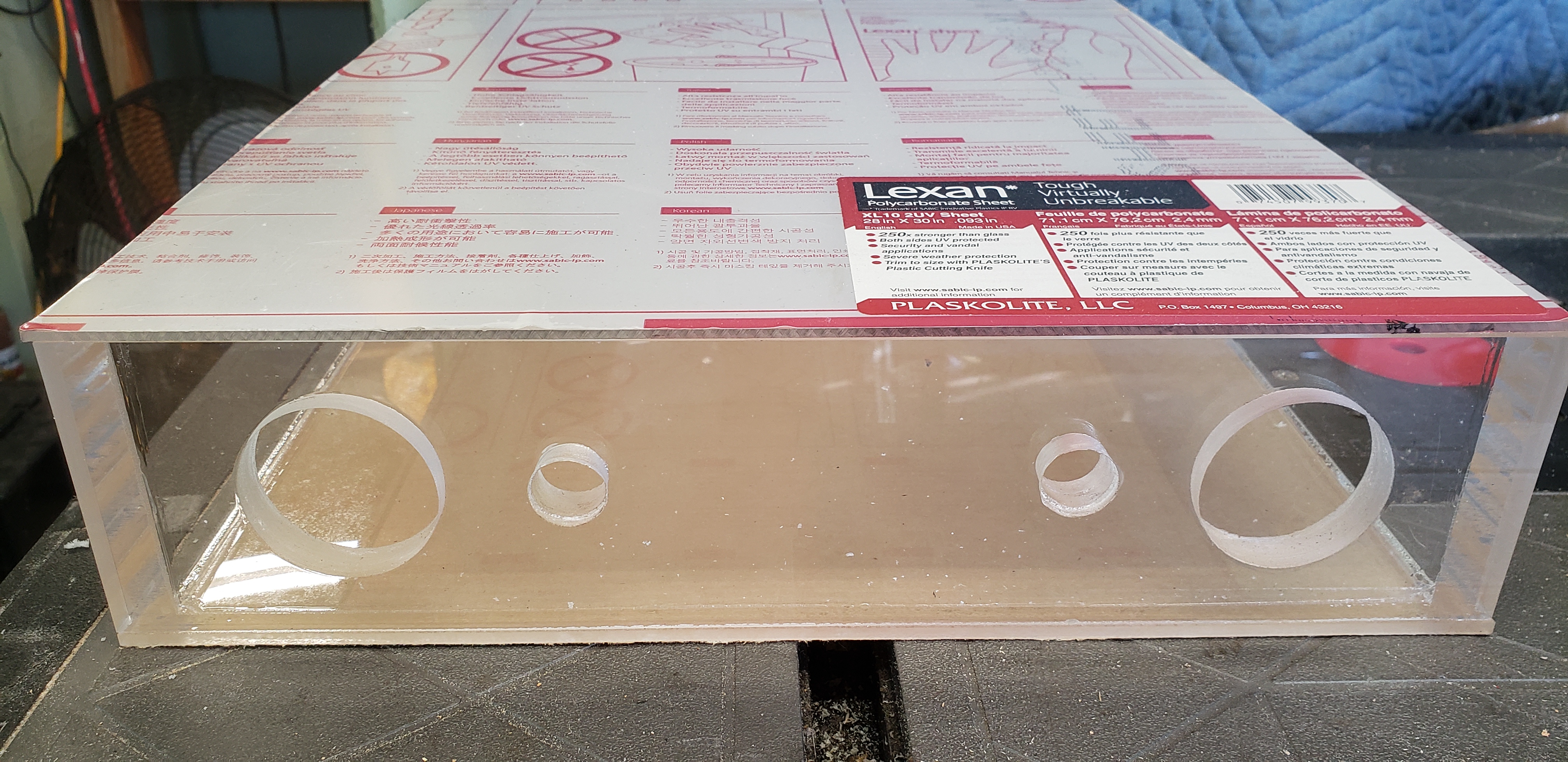
The waterproof enclosure alone is 8 lbs. 3.6 kg. Total battery weight is over 20lbs, so yea. About 10kg. I made my battery pretty much exactly to the Lift board battery specifications. It’s probably a couple pounds heavier then the lift battery though because of my case and plugs.
I wanted to have a long ride time (over 1 hour). That comes with weight. No way around it.
1 Like
thanks for fast answer)
i saw you not use bms, just rc-charger, its fast charge ? can you explain - how to make like you, build without bms, fast charge, and dont kill battery, plese ? 
Search my posts. Read up on understanding series and parallel battery connections, and read up on balance charging lithium batteries.
These batteries are very dangerous. You must learn all of these things before to start playing with them, before you try to build your own.
I have made several posts replying to other questions in the last month. This information should be a good start. But, please read enough to understand these things.
Any questions after learning this stuff, I’m happy to help.
tell me please, how much time is spent on exercises using your hobby-charger, and where you bought the samsung18650? nkon?))
I purchased cells from IMR.
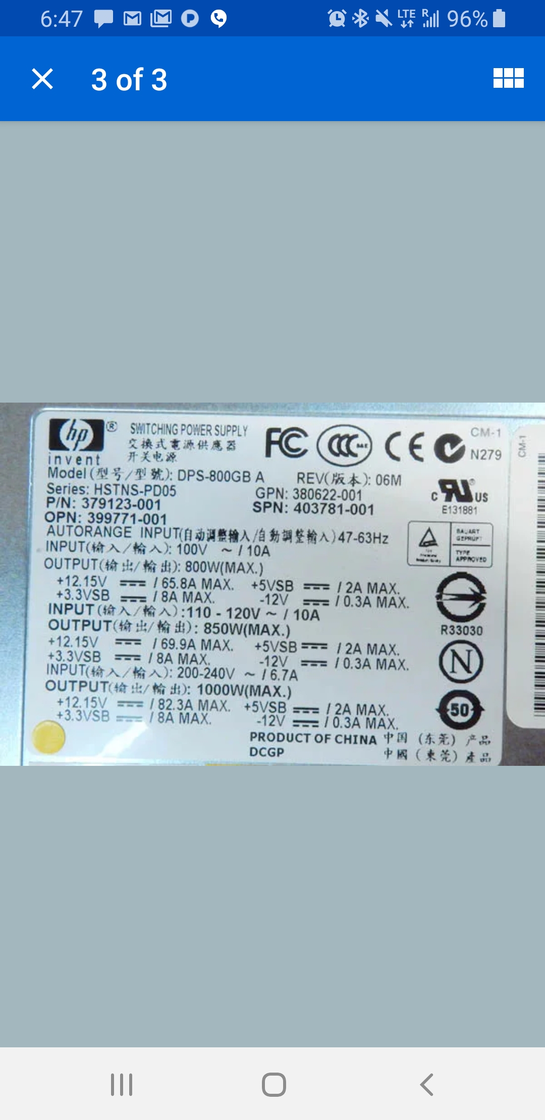
I run two icharger X8 chargers off one server power supply. It takes me 3hours to charge my 42a/hr 14s14p battery when fully depleted.
Details below.
The icharger X8 I use can only charge up to 8s battery. So, my battery is made as two 7s batteries. This charger is more then enough to charge at maximum rate these cells can handle. So, if you have two chargers you could charge the 14s14p battery in two hours.
Samsung 30Q cells are 3.0ah capacity. They can be charged at a rate of 1.5ah safely if you want them to have a long life. So, that means 2 hour charge time if the fastest the battery can be charged.
The icharger X8 is a 1100 watt charger. So, if you have a 1100 watt power supply, then this charger could charge half the battery (7s14p) faster then the battery can handle. 1100w÷28v=39.3a and 39.3a÷14p=2.8a per cell. So, limit change to 1.5a per cell = 21a.
If you buy one icharger X8, you’ll have to charge one pack at a time. So 4 hour charge time. I bought two of the icharger X8. Then I don’t have to remember to come back and swap the charger over to the other battery.
But, I run both chargers off one power supply. So, the capacity of the power supply is the limiting factor.
My power supply is a HP 1000w server power supply. And I use 110v. So, 850 watt max output. 850÷28=30a. So with two chargers that’s 15a per charger. 15a÷14=1.07a per cell. So, this is a 3 hour charge time for the whole 14s14p pack.

4 Likes
Thanks for good big answer
1 Like
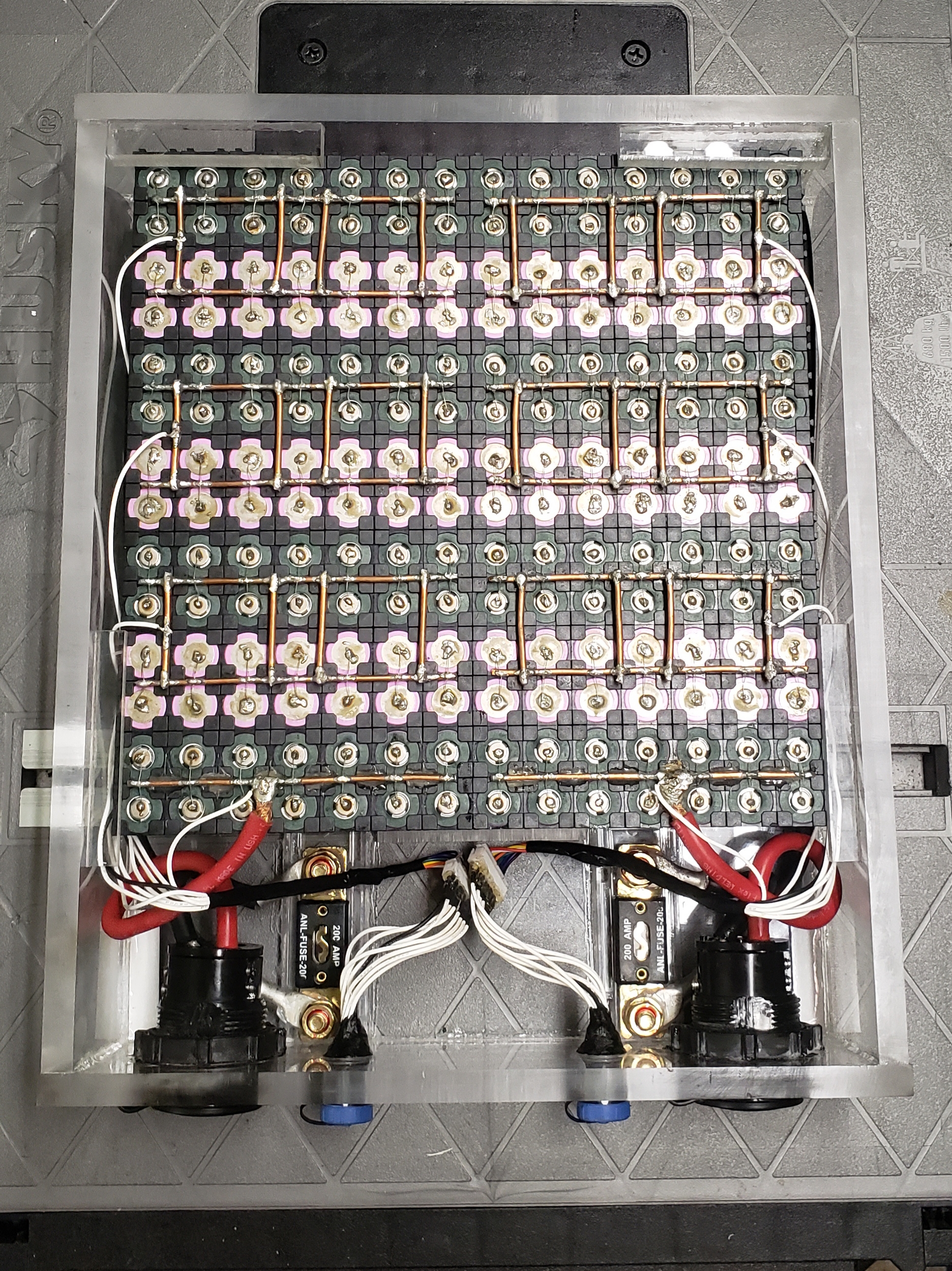
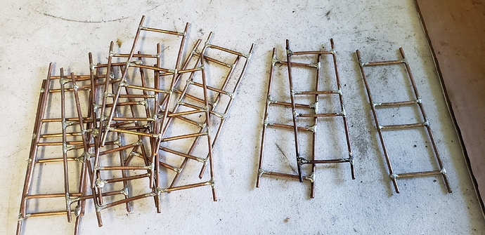
Working on my second battery.
The first battery design worked so good I’m basically doing the same thing on this build with just a few improvements.
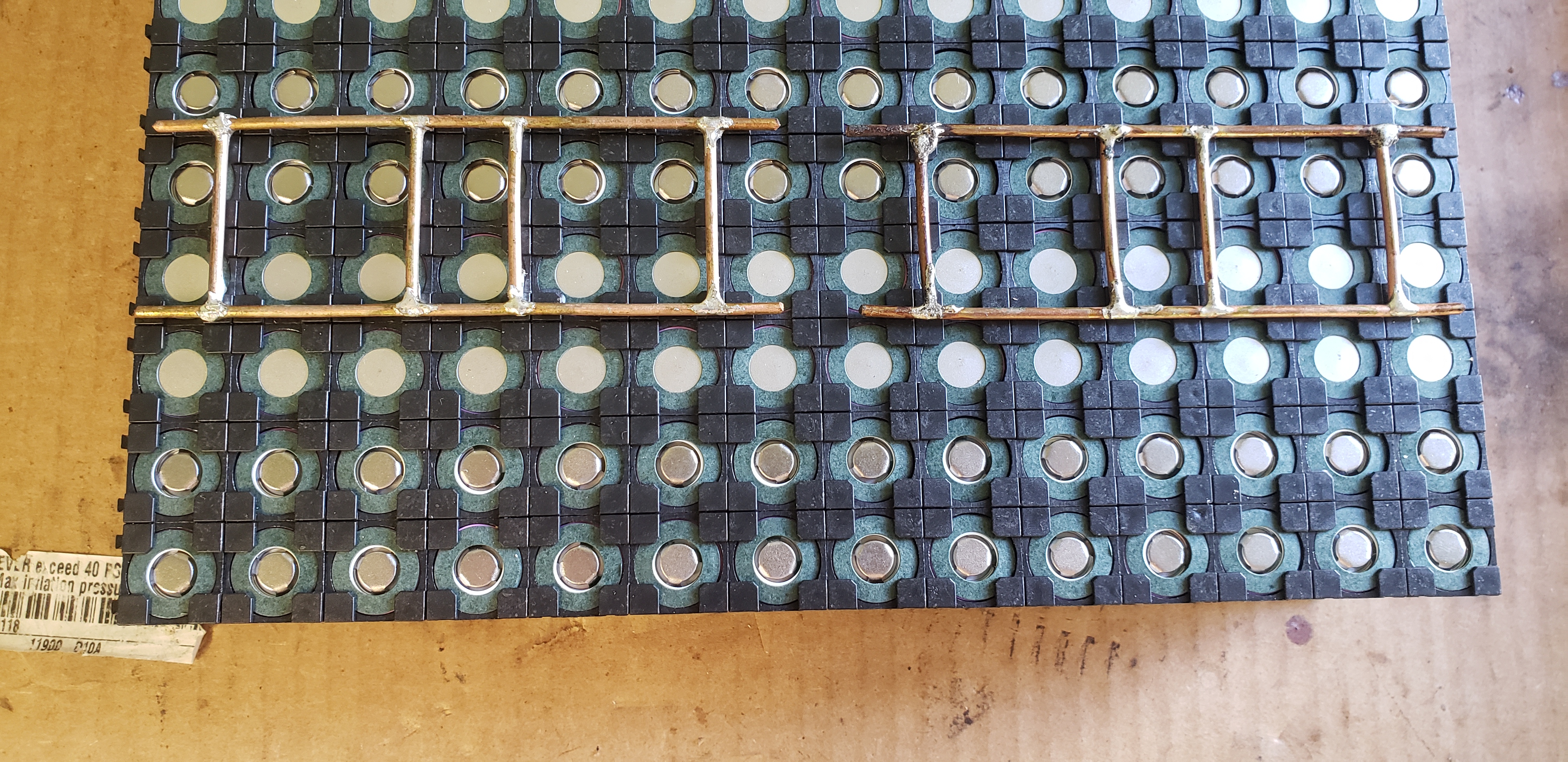
Got the bus bars premade thx to one of my friends / build partners. Thx @Telejacket.
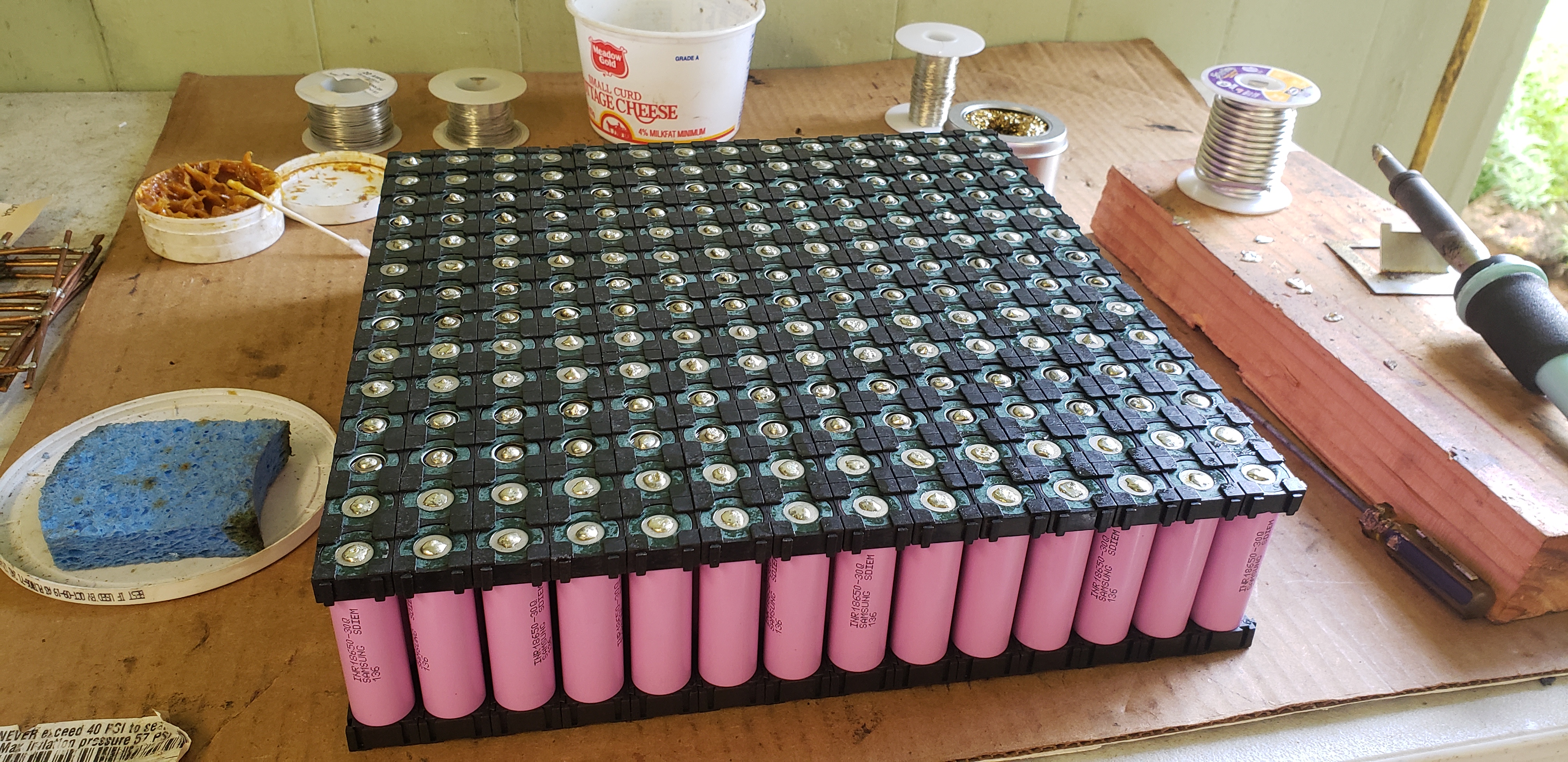
I got the battery sanded, fluxed, and tinned today. I hope to get this battery done this week.
Stay tuned for more updates.

4 Likes
Here’s a post I made in another thread.
I learned the importance of fusing the balance lead wires.
Don’t burn the house down guys!
![]()

2 Likes
Very nice work on the battery solution. I’ve read the whole thread at least once and parts of it 2 or 3 times in preparation for building something similar. Also the balanced fusing idea is great. I thought to decrease the complexity by putting some fuses in-line (but increase the wiring mess).
Some questions that I couldn’t understand after re-reading…
Can you clarify how you ran them in series in 1st or 2nd build? It appears you run the negative from the negative output of the 1st trolling motor connector into the lead for the 2nd trolling motor connector, then the negative from the 2nd motor into the ESC box. Hard to see from the picture.
What electronics do you have in the small waterproof cases? I’m confused as to what those are…
Did you hot glue the busbars (where the balancing fuses attach) to the battery spacers or how are they attached?
How did you waterproof the trolling motor connectors?
Many thanks - I’ll share my experience in building something similar as it comes together, which is soon, since I have all the parts on the way.
Hi.
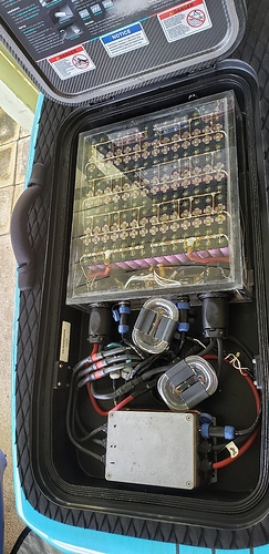
The battery packs are built as two separate batteries. In the waterproof case there are two completely separate 7s14p batteries. They each have their own Marinco battery connector with 200a fuse, and a 8 pin balance lead connector with each wire individually fused in my second build (highly recommend!).
I built it this way because I do not want a BMS
And I balance charge with a icharger X8 that can only charge up to 8s batteries. So, I charge as two separate batteries. But for use they are hooked together in series as one 14s14p battery. Does that make sense?
The bus bars that the battery leads hook to are prone to breaking the fuse wires from the pull. So I used a heavier gauge wire (20awg) instead of the 30awg used for the fuse wires. These cells are still fused because the other terminal has the 30awg fuse wire. Hot glue was not a good solution, and is not needed with this modification.
The aluminum box houses the ESC. The two small plastic boxes have the receiver in one and the low voltage alarms in the other. I did not have a long enough external antenna to put the receiver inside the aluminum box with the ESC in my first build in that picture.
I now have a 120cm long external antenna and the receiver has been moved to inside the aluminum box with the ESC. So, now I only have one of the small plastic boxes which houses the low voltage alarms.
Because there is no BMS it is very important to balance charge the battery, and to make sure never to let any cell voltage to drop below 2.5v during use. The voltage alarms are simply for added security. So I know if any cell voltage drops to the value I set, which is 3.0v. I hear it beeping and have about 5-10 minutes to get back to shore before 2.5v.
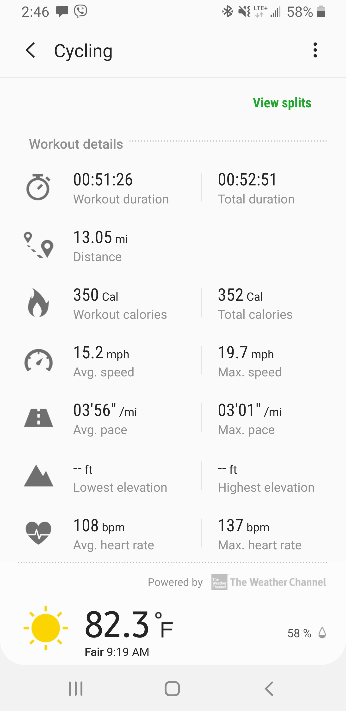
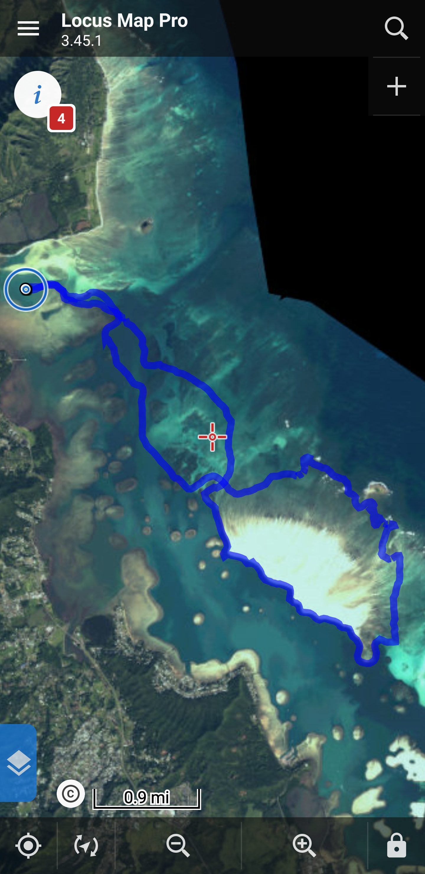
The battery indicator on the remote works well, and I always know when to head back to shore without relying on the voltage alarm. But, I do really long rides by myself, 15-18 miles round trip. If the battery has a malfunction, or a individual cell starts to drop more then the others, the voltage alarm will sound, and I will know to turn around and head back to shore.
I don’t trust BMS. Never trust a BMS!
I was still at 3.5v after this ride. 


2 Likes
Yes, I got the configuration completely: 2 x 7s14p, with 2 x external chargers to control charge to each battery, fuses on each battery, fuses for each balance connector, and run in series once it leaves the battery enclosure. All makes sense. I was a little confused on the way you did the series connection outside the enclosure in the trolling connectors, but think I figured it out from the pic.
Busbars -
I called these busbars, but maybe a different name for them -
They are held in place by the solder from the fused wires alone? No glue or anything else to secure them?
Small external boxes for the smaller electronics - got it.
On the low voltage alarm, I assume you used something like this low voltage alarm that interfaces with the charger balance connector? So you hook those connectors up each time you put the battery back in the board?
Thanks again - that looks like an awesome 18 mile run!