Went for a test run on my 80100 80Kv build this am and had a virtually immediate failure of my battery monitor. I was running the motor up in the water with the board against the dock. As I was easing into the throttle I saw around 5000W on the meter and the a spark from behind the screen and the unit (and everything downstream) shutdown. It was supposed to be rated for 200A and I estimate I was at about 60% of that when it failed and it was only there for a couple seconds. I was using this meter successfully with my smaller power glider motor but despite its 200A rating, it didnt stand a chance with the larger 80100. I have a 150A breaker just before this meter and it didnt trip for what its worth (not that it should have) and I am running 2X 20000mah turnigy 6S in series (12S).
Previously I used the 150A version of this meter with the powerglider motor and blew it so i upgraded to this 200A unit which had much larger wires. Now its toast.
What meters are you guys running with success? It would be great to have something that logs as well. The meters I have been using just show you real time voltage and current. This would be placed behind a window on my electronics enclosure so I can keep track of battery voltage while riding. Maybe something that measures current via hall effect instead of all that power running through the meter? I am running a Flier 400 boat esc.
For future builds stay away from the HTRC / Cheap Amazon meters! It took me buying two of these to learn this lesson.
I solved that by switching to the VESC, you get all the data you need, battery current, motor current, temperatures,… add a BT module and you can nicely log and monitor everything on your phone.
Else maybe try a current monitor with a hall sensor clip.
This is a good cheap option, I used it with my first extremely inneficient efoil that cruised at around 2800w, this power meter survived that, while being inside the box with the batteries and scorching ESC’S. I did upgrade the wires to 8AWG. It also logs max power, max current, time on, wh used, ah used and a few other things.
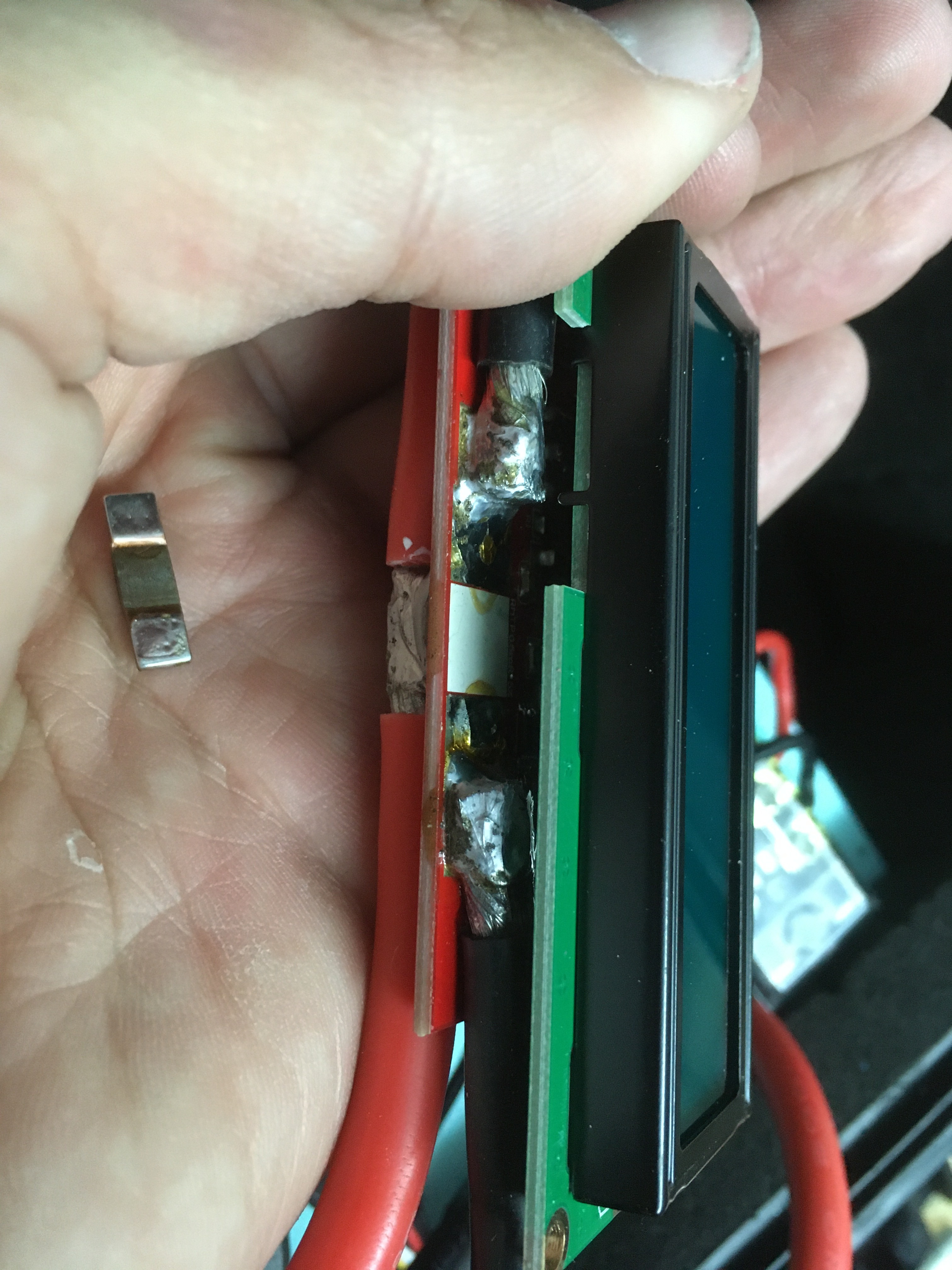
Found the problem with the failed meter… I took it apart and the shunt resistor fell right out. I guess the solder got so hot that it melted and came undone. I can resolder it but I wonder if it will just come unsoldered again?
Thanks for the feedback guys. I wish I had a VESC but just recently got this Flier 400 and would like to stick with it since I have it. I like the idea of a hall effect type sensor only because i won’t ever have to worry about it burning up again like the shunt style. We pushing alot of power through these components so i feel like using something that all that power doesnt need to pass through is the safest bet.
i’m using eLogger V4 with GPS , RPM and temp sensors… a bit expensive solution, but the data is good. it worked well for me, but others had less happy experience…
I had one of those but after only getting to use it like twice i accidentally wired it incorrectly and tried to send all the current through the esc lead and smoked it. Im still pissed about it. I havent thought about trying to repair it but now that we are talking about it, i wonder if it could be fixed by replacing the burnt component?
As far as the real time display in am looking for i ended up ordering one of these last night: Sorry! Something went wrong!
It uses a hall effect sensor so hopefully I wont have any overheating issues like I had with my last two shunt style meters. That fact that those were getting so hot also makes me think they were sucking a considerable amount of power from my batteries so hopefully this one will be more efficient.
I also went ahead and ordered two of these temp monitors so i can keep tabs on my battery temps and closed loop cooling water temp. Amazon.com
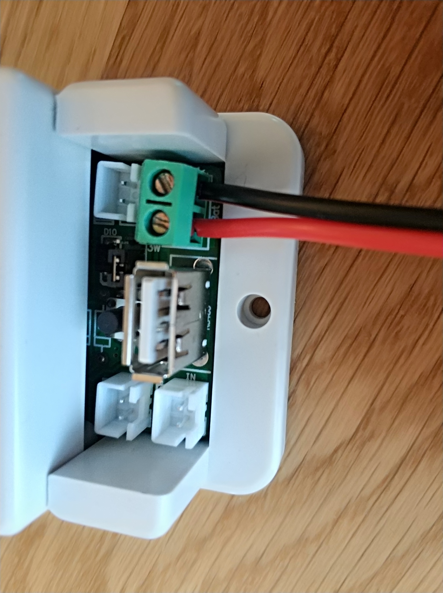
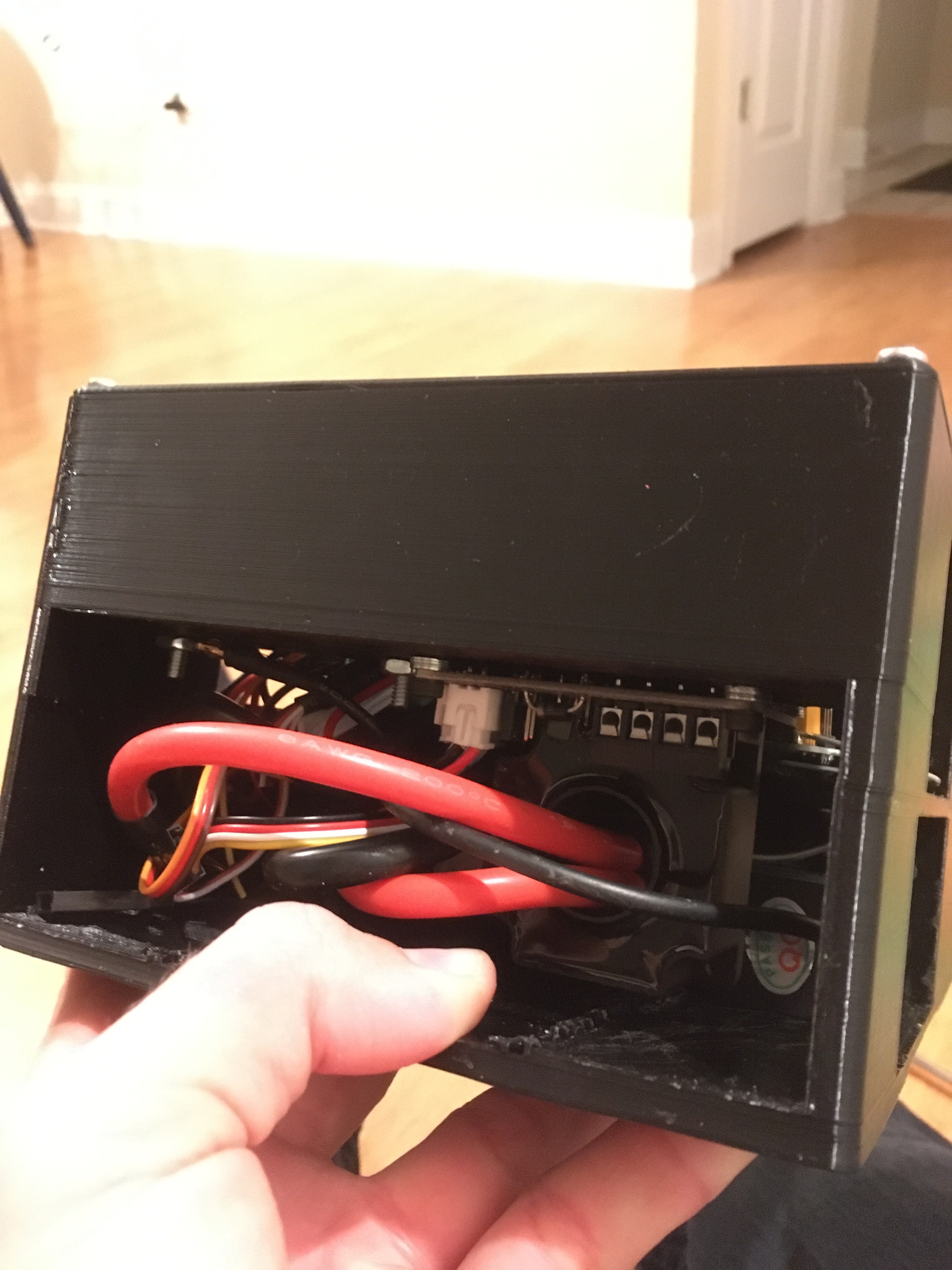
So far I have only provisionally wired it for testing purposes. Later everything will be installed in a waterproof box.
I take the power supply directly from the battery after the fuse. External power supply is only needed if your battery has more than 80V.
The hall sensor is simply plugged over the supply cable.
The display can be supplied via USB cable on the controller or separately. The data is transmitted wirelessly. The USB connection between Display and controller is therefore not needed.
Is a smaller and more acurate hall sensor available?
Can it beat a shunt regarding precision?
The shunt of my BMS wheighs 100g minimum. It produces very little heat.
The problem is the time and heat thereby. It is no problem, to heat a resistor for a few seconds, but after some minutes such PCB soldered shunts are getting hot and you need a concept to cool them.
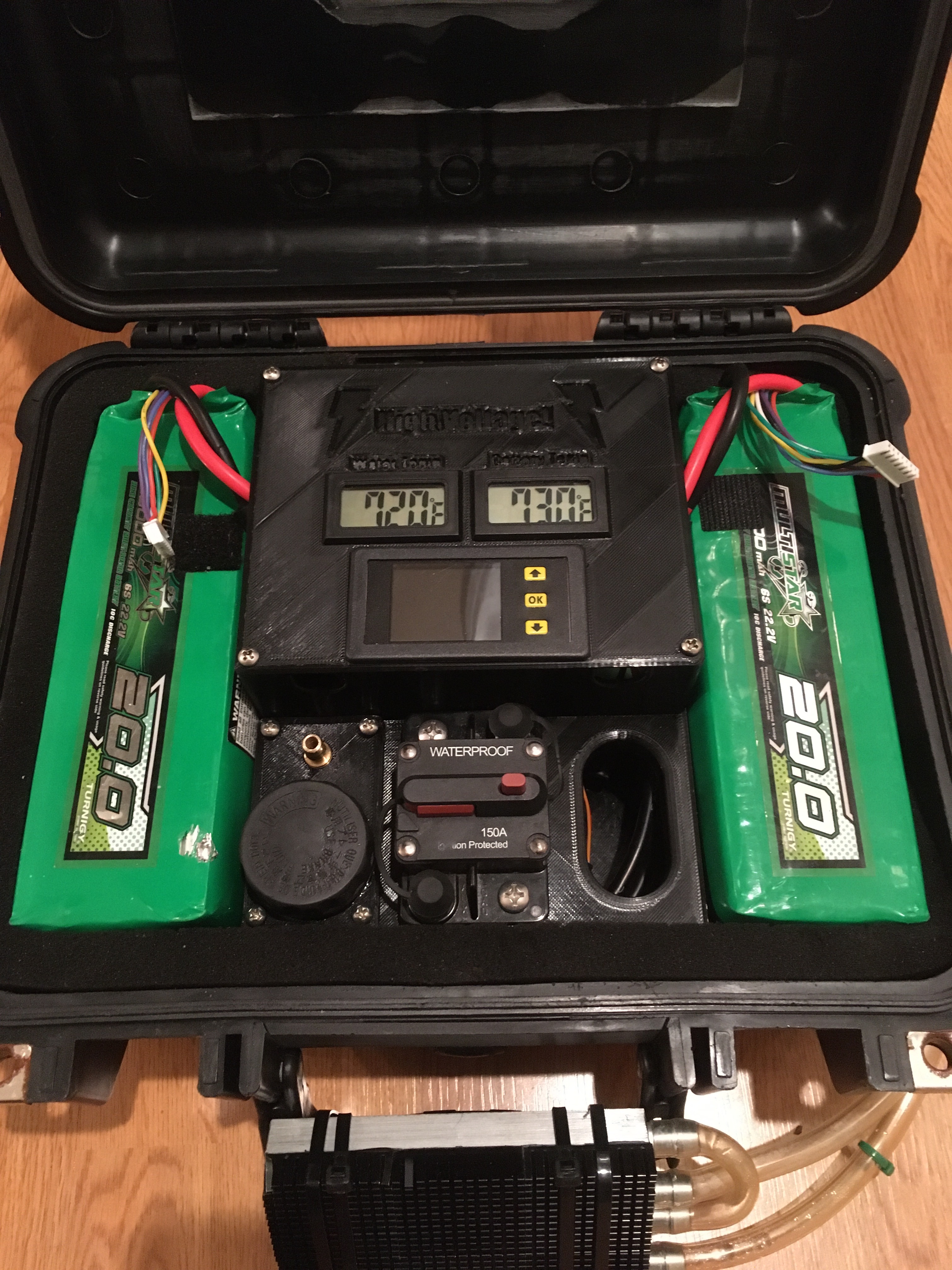
I have been using this hall style sensor for a while now and love it. I doesnt have the white box like the one above. Just the black screen and the hall sensor part. It has a really colorful bright screen too.
I was having the same problem you are talking about where I kept overheating shunts and they would come desoldered from the PCB. Obviously I dont have to worry about that with the hall effect style sensor.
What is the item in the picture?
Also you say the sensor goes on the supply cable? But it looks like it is on the negative in the picture and the directions from manufactuer?
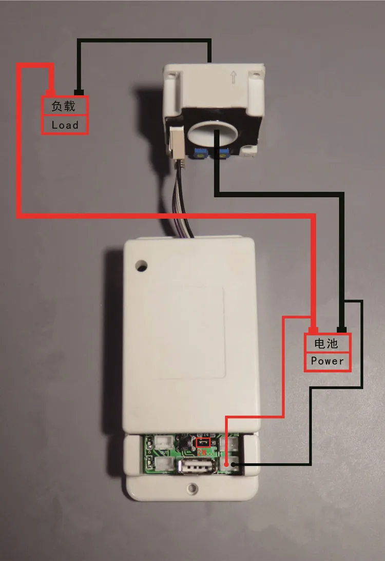
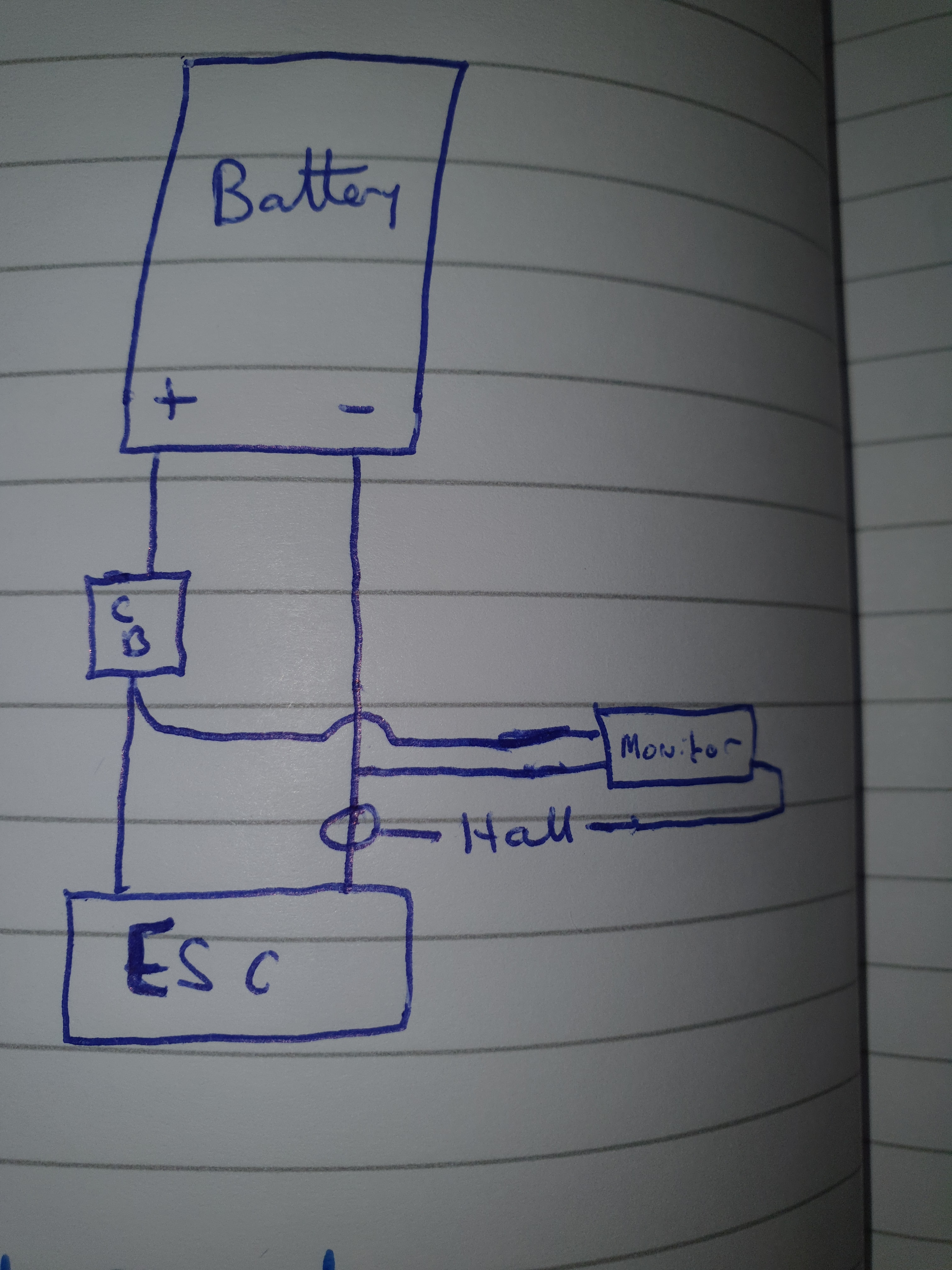
I was planning to take the unit supply off the battery after the CB, and placing the hall sensor on the negative just as it comes out of the ESC - apologies for the bad sketch.
I have my hall sensor installed over the positive battery cable just before going into the ESC. I dont think it matters which path (positive or negative) you install it on. On my board its: Battery positive --> 150A breaker–> hall sensor --> ESC --> negative wire from esc straight back to batteries.
Its a 150A Car-HiFi Fuse. But will be later replaced by an electronic fuse (Circuit Braker).
It does not matter if the hall sensor is placed in the plus or minus line.
Depending on this, only the direction (arrow on the sensor) must be considered, otherwise the display will show a negative ampere value. Because the device can measure whether current is “coming” (charging) or “going” (consuming).
in the same box i think no problem …i am going use one similar not wireless but less bulky …on the aliexpress pics you can see the nrf24o1 rx 2.4ghtz pluged rear the screen , so in theory if there is water between the screen box and in a other box the hall sensor unit can loose signal or not becaue the board isn’t to long… if you use to many frequency in the board radio …screen or other same frequency in same time in litle space it will have noise … and we can maybe have trouble with the throtle response, it s my question of the moment
I tested the signal range. Stable signal up to 10m and a wall (brick wall) in between.
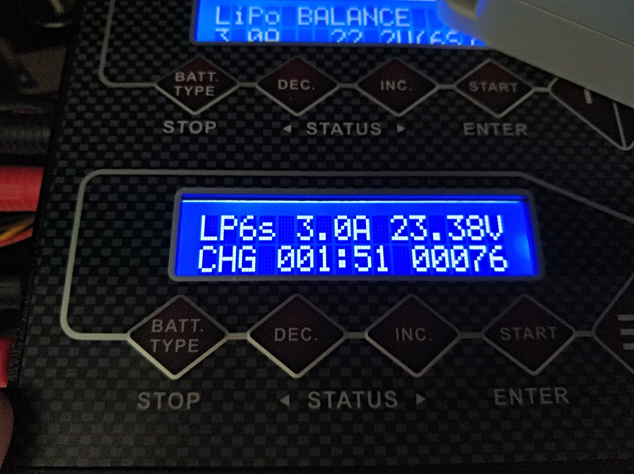
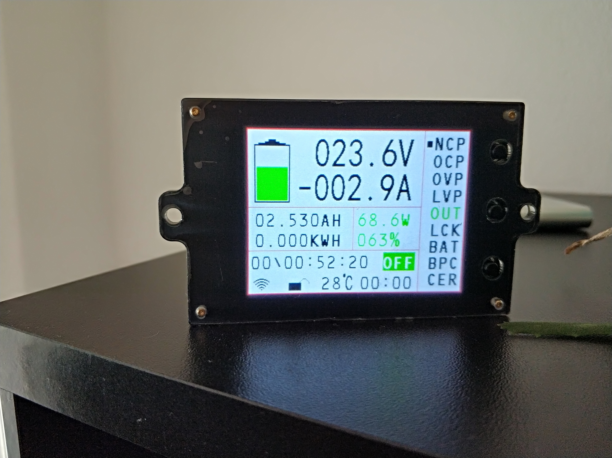
Accuracy tested: For this I put the Hall sensor into the charging cable and compared it with the charging display.
Charger: 3.0A, Current Meter: 2.9A
Voltage was 0.1V lower than on the charger display. Voltage on the photo is not representative because the battery voltage between the two photos had already increased while charging.
Hello. I have the same unit. I wired it up today but get some strange readings.
When the minus wire goes from battery to esc in arrow direction through the sensor, I get negativ A reading. BUT the Ah is count down, as it should be (I think) AND the kWh value does not count up, it stays at 0.
If I run minus from battery to esc against arrow direction through the sensor I get positive A reading BUT the Ah value is also count up. Adding Ah to the value of the battery ( that’s nonsense) And the kWh value is correct.
Is it with your unit the same or different?


)