It looks great again and like you have put a lot of tought into it.
If you have a seperate logic board, will you be able to use 2 Layer boards or is it just not worth the hassle?
It looks like it has most of the components on one side. If so I would opt only for the stencil and hot plate solder it. Only if you want to make many prototypes I would endure the additinal waiting for the assambly.
Elaborated Design! http://efoil.builders/uploads/default/original/2X/8/83244bfa1393dc97026b393869a0eb5702197fd1.jpeg
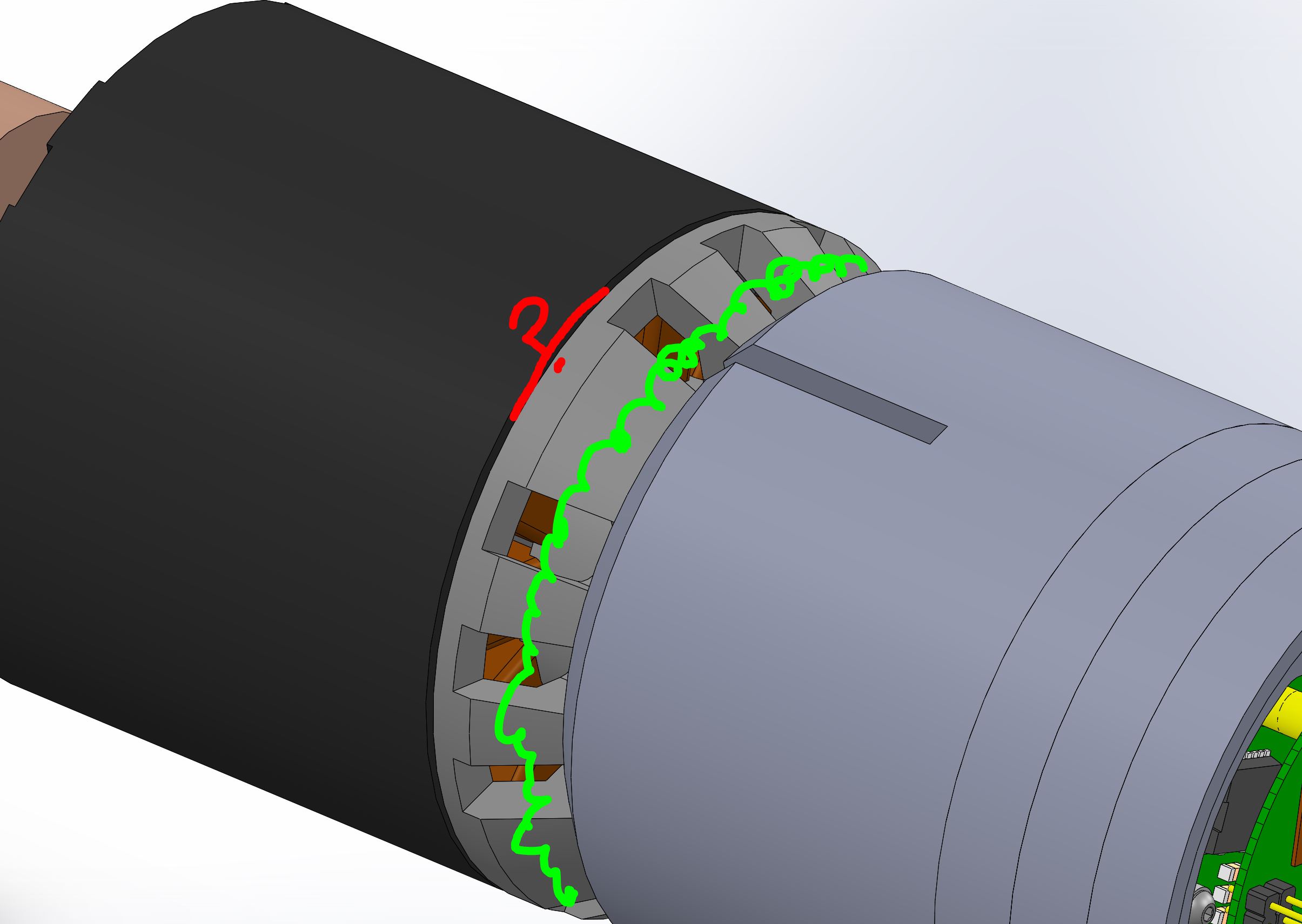
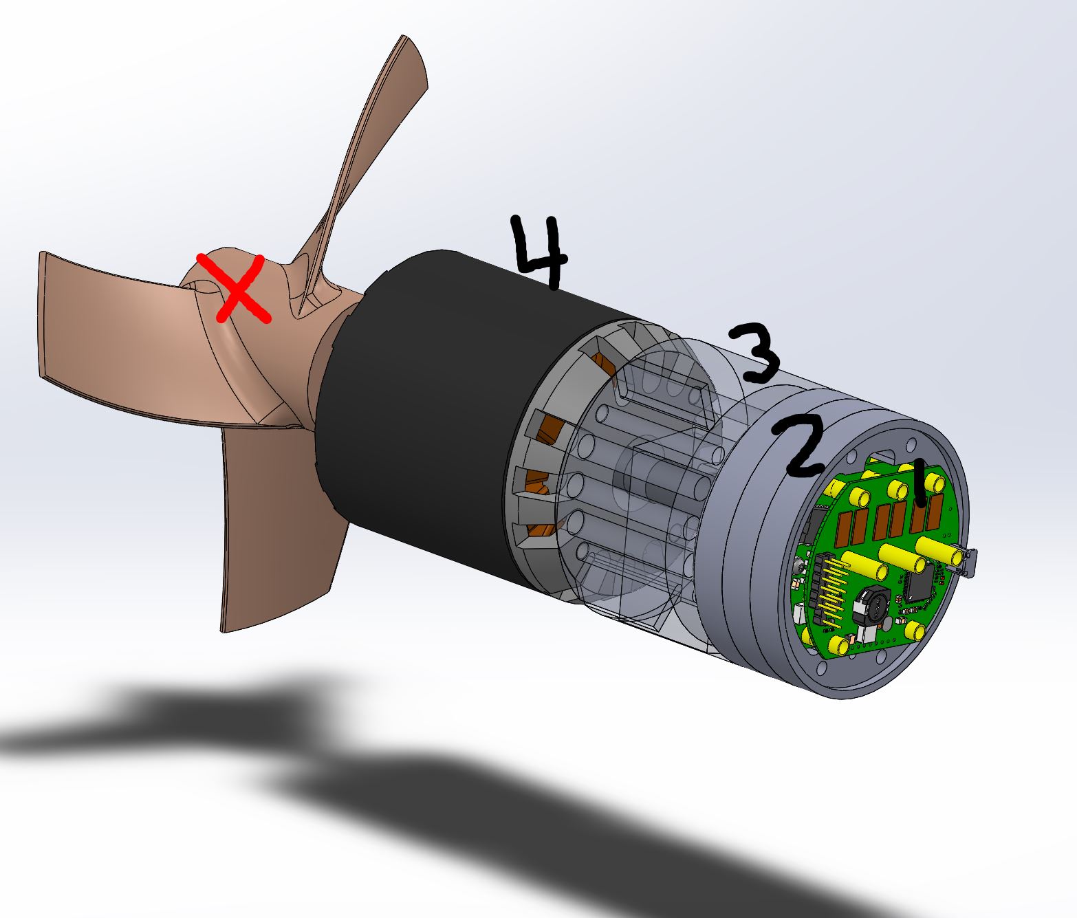
You should design a 90% cover of the all motor openings. This prevents sand inside the motor, so all openings which are standing still should be covered, so only the rotating have small openings. The water passes through the “mill”, the gap between rotor and hub, all heavy particles will be rejected to insert into the motor, only water is allowed.
So the only problem remaining is the circlip to not loose the rotor when braking.
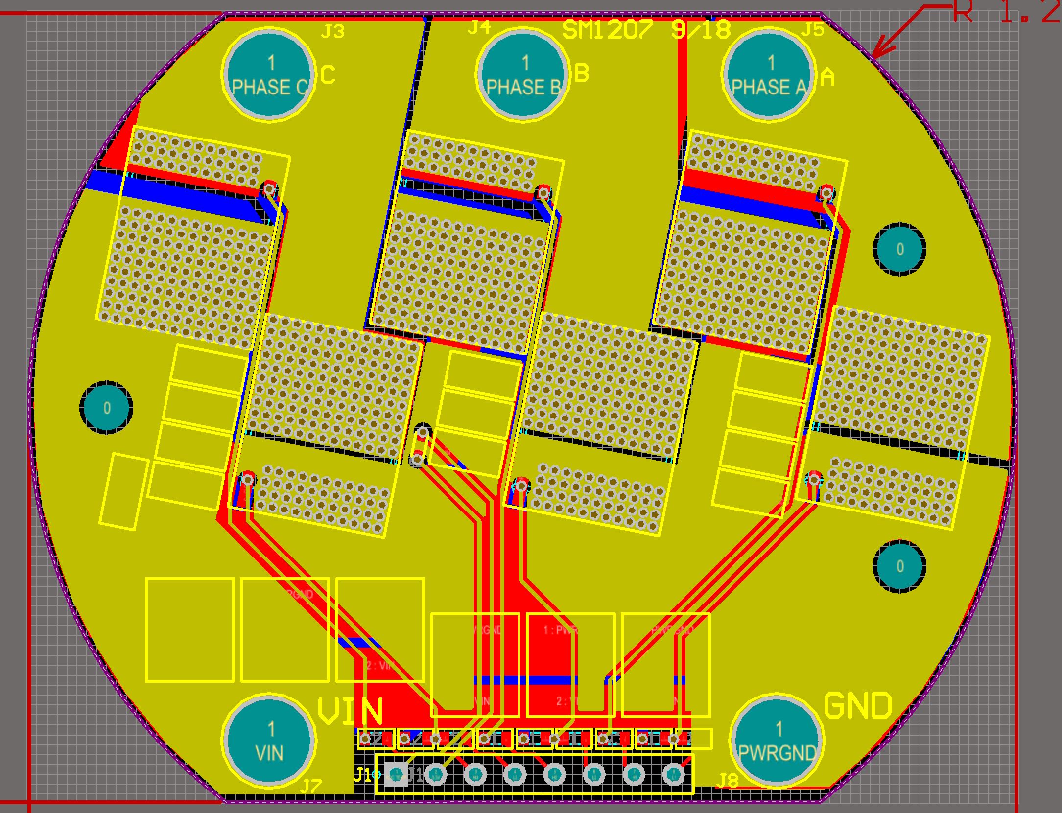
@Flo The high power stuff is on the top and bottom layers. It would be cool to do a 2 layer aluminum substrate board, but this layout positioning isn’t super friendly for routing the gate drive wires.
@PowerGlider I’d love to cover the openings. I am going with a “flooded design” because a bunch of ROV/Navy dudes told me that oil-filled, shaft sealed designs are known to fail much more than flooded designs, even when the ROV operates in dirty environments. Perhaps I can put some reticulated filter foam around the stator openings. As long as the motor is spinning and the thruster is moving, the openings on the back of the rotor should be a low pressure zone, sucking clean water through the foam. But how do we put a filter on the crevice between the rotor and the stator?
@maxanderson I’ll be building and testing this board week after next I’ll get some video, and everyone can see if this design can meet their requirements. If it does, then we can put together a group buy to get whatever volume pricing we can get.
If people like the ESC design, it would also be good if we can get a group to agree on most-of-the-thruster design, so we can also save money on cnc Aluminum parts like ESC heat sinks, motor adapter, prop adapters, prop guards, etc.
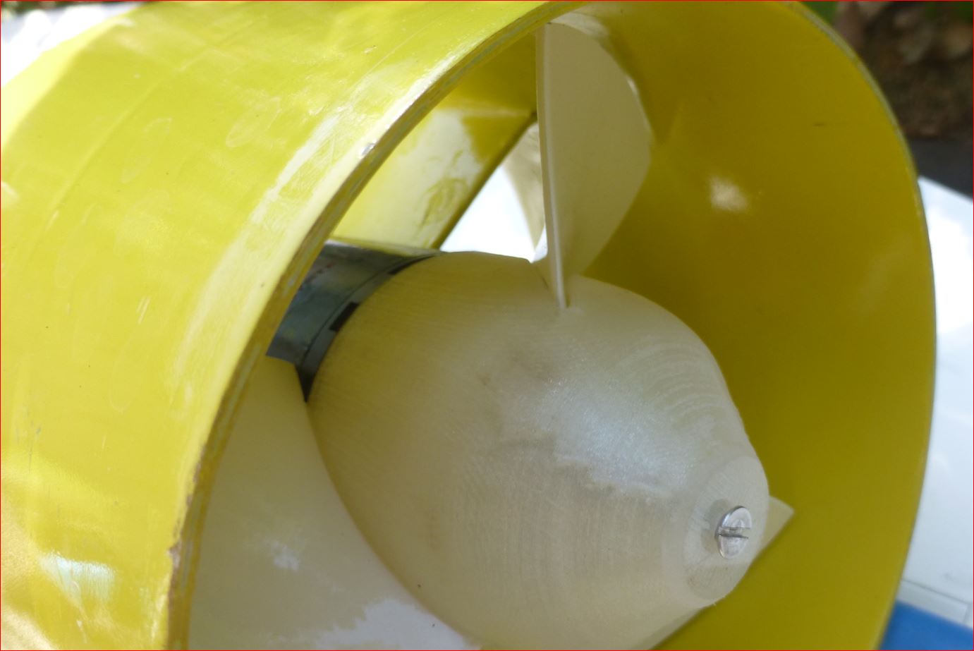
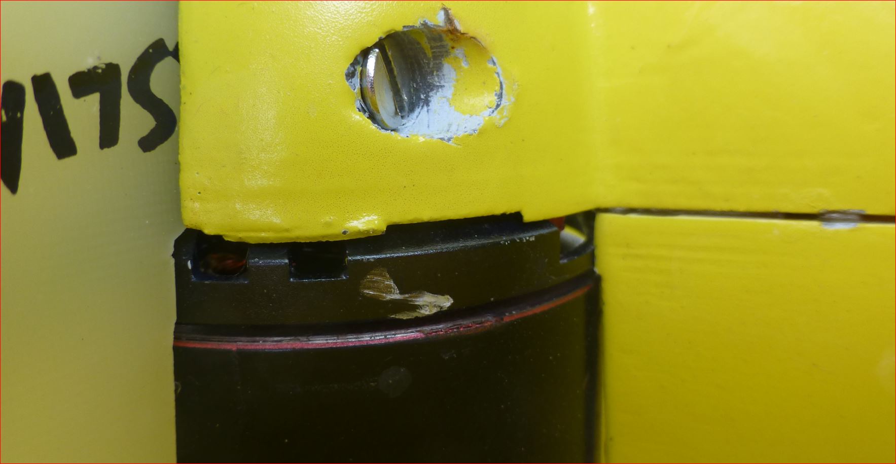
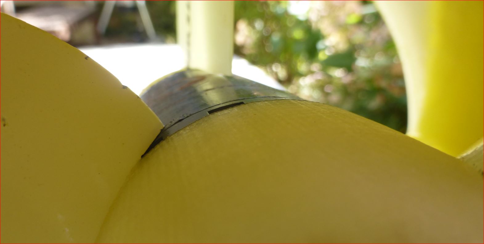
Right, you san seal at the green line and then you suck the water through the red marked slot only. It is not so dramatical. Here i have some details from my design, after it crashed into the beach at high speed, sucking pebbles and sand. Note the marks and scratches. It is still working perfectly, after reglueing the duct to the fin. This is not my end design, i want to experiment with different pitches and this construction is for eased swapping of heavily cut props, so the electric connection does not need to be removed to reach the circlip. I can swap the props without dismounting everything. The drawback is the not perfectly aligned 3D printed spinner.
It would be good to have a design which fits to 63mm outrunners as well.
If the cooling is good, one power board should be enough, 100A*50V is 5kW already, that should be enough for the 63mm outrunners. I also have plans to try 50mm diameter outrunners.
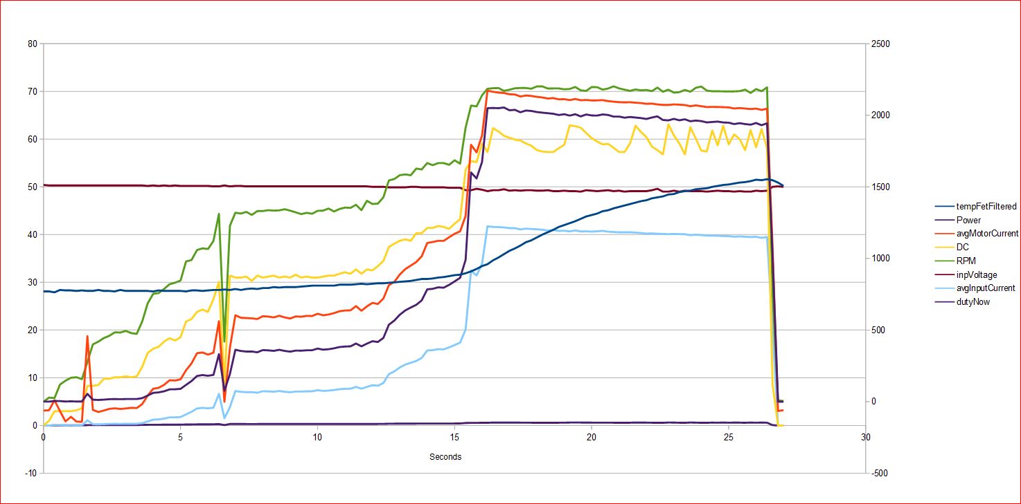
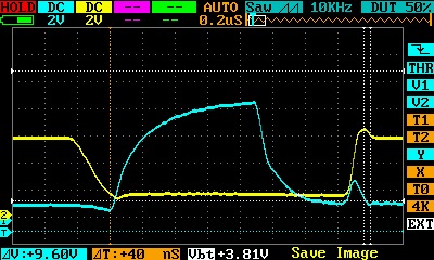
My VESC is really weak, the behaviour completely unclear to me, especially the DC, yellow.
I run the original FW with 0005 and phase current 90A. It is hitting fault code 4, FAULT_CODE_ABS_OVER_CURRENT
if i am correct.
Is this a fault in FW, because a single (and maybe wrong event captured anyhow) is repeatedly added into the FIR queue? Is the sampling timepoint correct or happening during a switching process? Is the filter time correctly chosen? How can it be, that the current is not controllable, what is causing this?
Then I used a leather belt wrapped around it to load it down when I want
Used Vesc-tool and oscilloscope to capture sampled data.
Varied the Maximum Switching Frequency, Absolute max current, Slow ABS Current Limit FW values with Vesc-tool.
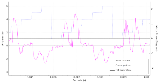
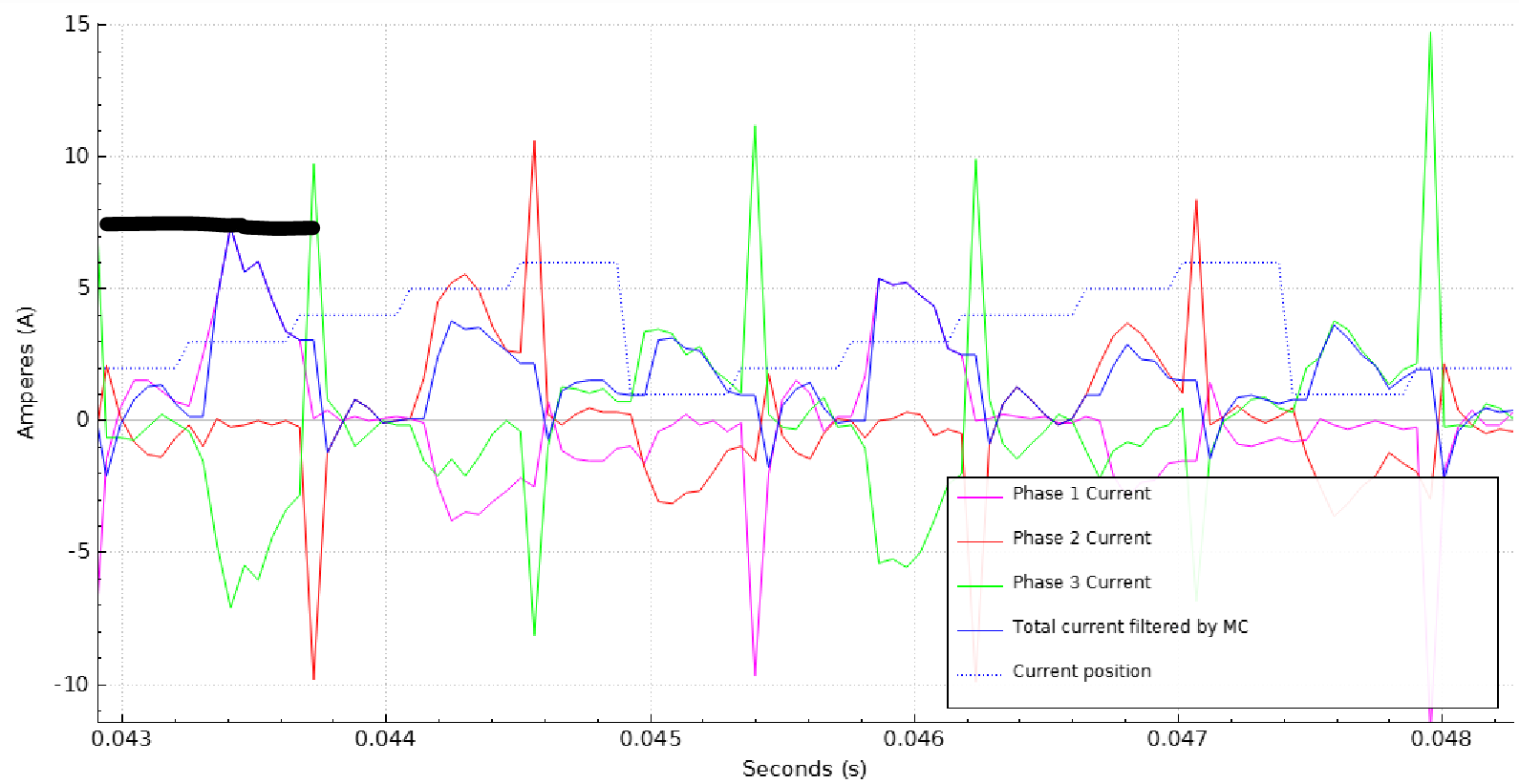
Here’s what I found: If you run at 40kHz sampling, you can see individual humps of current starting from zero, going high, and winding back at zero on each commutation step
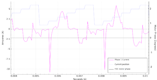
Switching at 20kHz, you get half the resolution, and very strange spikes during commutation. Those are probably not real. They could be a digital artifact, but there are definitely big transients and second order oscillation on the o-scope during commutation so who knows. They don’t seem to matter.
Here is a comparison of the oscilloscope and the VESC data (red plot/phase 1):
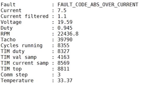
The commutation spikes don’t seem to affect anything. They happen at the ends of the commutation cycles, are way above the absolute overcurrent threshold, and I think the VESC ignores them. The peaks that happen in the middle of the commutation cycle cause errors. When I turned on the “slow abs current limit” feature, over-current errors happen less, but they still happen. Here is an error that I caused while sampling:
“Current filtered” is 1.1A at the same time the phase currents are touching 7.5A. Instantaneous phase currents are much higher than average motor current. This data is collected at low power, so there could be some noise and some small offset corrupting the data. With high power, I would guess the peak phase currents are around 3-4x the average currents. I haven’t done a sample capture yet with my new high power load setup.
I can confirm your mesurements, my abs max current is also much higher than the avarage max current. I did test this with 80A and it showed twice the max current with the Sampling Feature in the Vesc-tool.
I compiled my own firmware and boosted the abs max current as I have custum cooling that will allow to use higher currents. This removed the Fault_abs_over_current hickups. However I still get sometimes throttled down because of the current peaks, this limits my duty to 75% then. I will have to research this further when my setup is running again. I have no physical explanation for it, at least none that I think is reasonable, but I first experienced those problems when I lengthended my motor wires from ~15cm to 1,5m of 16mm².
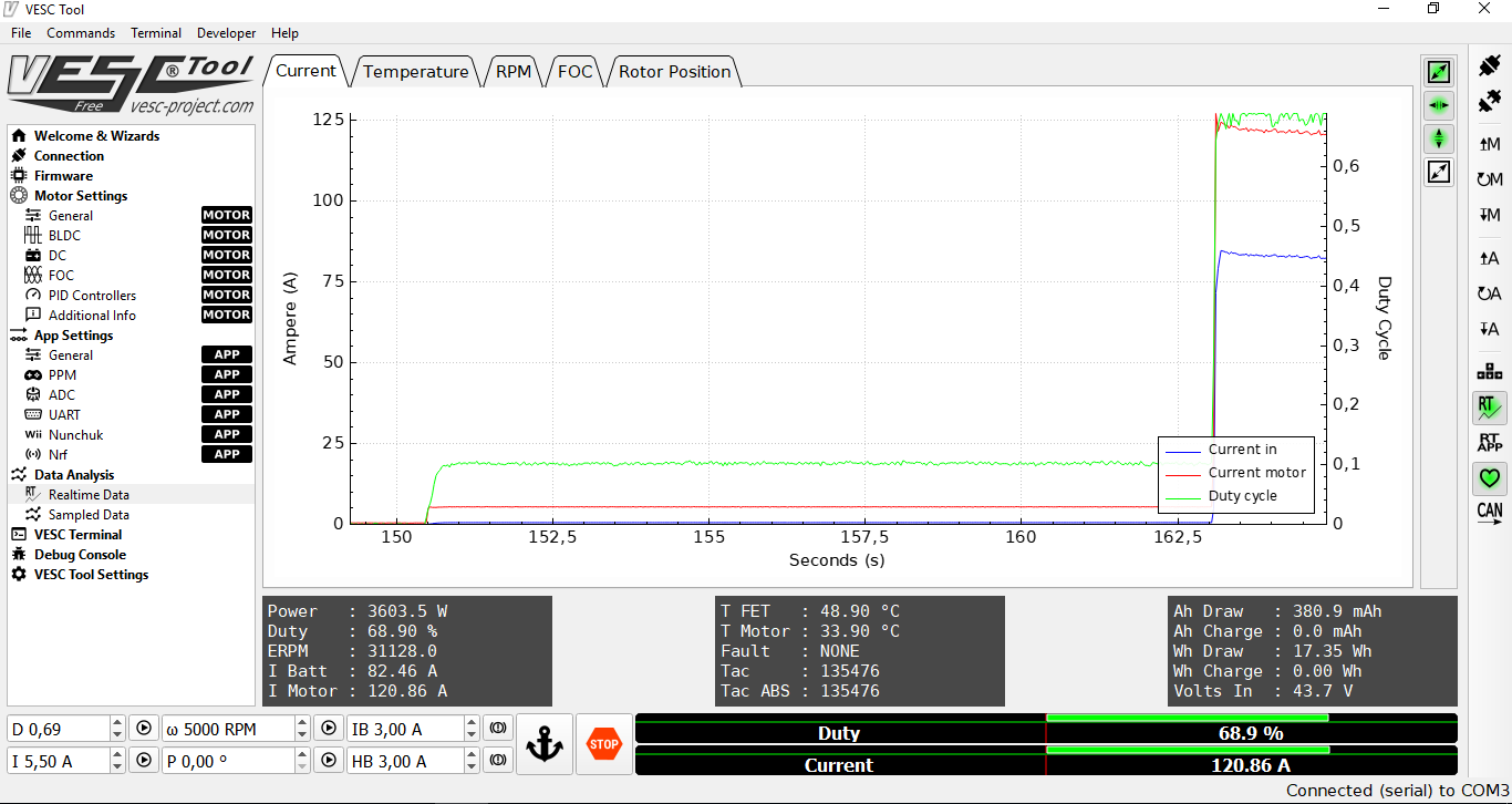
And it is possible then to get to higher currents here is a short burst without watercooling of 120A:
Unfortunately I cannot make another measurement now. I’m currently reconfiguring my setup. @PowerGlider : Do you really get 30kg of thrust at ~2250rpm? That’s pretty cool for 2kW Input power. I might just have to order one of your motors now.
Even if the measurement was crappy for some reason, i use to look for the input power on my TF02 instrument, and it never exceeds 2.4kW, this happens after a few seconds when reaching top speed normally. This time with the crane scale it was 28-31kg. We did 4 measurements, all had the same result. A week before we recorded 33kg, but that was with a very cheap luggage scale capturing maximum weight. You can barely hold it with two hands and a big handle, sitting on a rack. The amount of water pushing through the duct is enormous. If i had 80A motor current it would be higher bollard thrust…
…maybe we stop the discussion about thrust here, this thread is about custom VESC and the problems arising.
The slow abs current limit is calculated in BLDC mode like this:
So, as a first step the outliers are truncated to 120% of the maximum threshold. Than a FIR filter with a length of 16 is implemented. This is rather slow i think. How can it be, that this error is reached at all? I suspect it is an implementation problem or a concept problem, there is something wrong. How can it be, that the control over the current is lost for 16 and even more control cycles? Ok, a commutation happens, how many control cycles is this? one or several? If the commutation happens too early or too late, could this cause the error? @Flo, what do you miss, when disabling the error reaction at all? General current control is still active i expect.
Same here, I did not touch the switching code in the firmware. -> BLDC Mode, 3-40kHz switching frequency.
Or is there a way to monitor the current switching frequency directly from the vesc without attaching a scope?
" The current simply becomes noisy and gets aliasing at certain motor phase angles at high speed when using two shunts. " benjamin stated in April this year. https://vesc-project.com/node/403
Now that he is advertising the improvements gained by 3 shunt design, the weaknesses of HW 4 are discussed in detail.
How is the current measurement working in HW4? Is it measured during the Off-phase of the high side fets, when the low side fets short the current during the remaining 5% (of 95% maximum dutycycle). That would mean that if running with 40kHz, the time window for measuring the current would only be 1.25µs. That fits to the osci picture i already posted 3 weeks ago.
It is around 1.25µs long.
Now for me the question is, if the signal becomes so noisy, will the VESC be able to climb over the 60-80% problem region ever?
“This can be noted on HW4 where a commanded constant current will give a non-linear acceleration: it will be linear to around 60% of full speed, then it will decrease for a bit up to around 80 % and then it will increase from 80% to 100%.”
In the past there was written a lot about motor saturation as an excuse that vesc looses sync, but i do not believe in that, since i got 3.5kW through an APS 6374 with a water cooled YEP 120A without loosing sync.
So, next test will be with Abs over current set to a higher level, this is the solution benjamin spreads through the last year.
I am still confident that this will solve your problem for now. I have only tested this with my 200kv 6374 motor, but I ordered your motor and prop today so I can test your setup, too.
I think all of this is why we are In the „custom ESC“ thread. Your scope image shows just how weak the gate drive really is. And from your post I understand that the current measurement is also more involved in the control scheme for BLDC mode as we thought. So three phase shunts with individual amplifiers and a strong gate drive is necessary for a custom esc. But thats for the wintertime, I think for this years tests the vesc will be fine.
I do not think the BLDC detection is so complex to use the current measurement, but the aliasing current reading at a certain point in the power curve or DC curve could mean, that the vesc is not getting above this point. If it reads back 180A phase current with the normal limit set to 80 or 90A would mean it is decreasing the DC to decrease the phase current.
So at the moment i am stuck with around 60% DC, thats the drama. I need to go through this range quickly. Its a resonance effect. Very rare, but interesting, that you can get stuck there, ending in a temporary shutoff and sometimes a jump into the water.
This current measurement is noisy from the very basics. Low sampling time at high power with a lot of noise from previous switching, almost no analog filter, double sampling was tried but died.
Ok, but never mind, maybe this Abs limit is not necessary at all, so lets vary the threshold to find out what is going on.
@PowerGlider I agree, bump up your absolute max current way up or comment out the check.
I finished my dyna-mometer! I can now test any esc and motor to any current at any speed. Unfortunately the KDE7215 motor I have is somewhat limited, and gets REALLY HOT at 50A. I have a video where you can see that it’s at 50A for about 1 minute, and a shorter video where you can’t see anything but it touched 87A for a fraction of a second. I purchased a new APS80100 130kV that can supposedly take 200A, but its on backorder
Learning a lot from the testing.
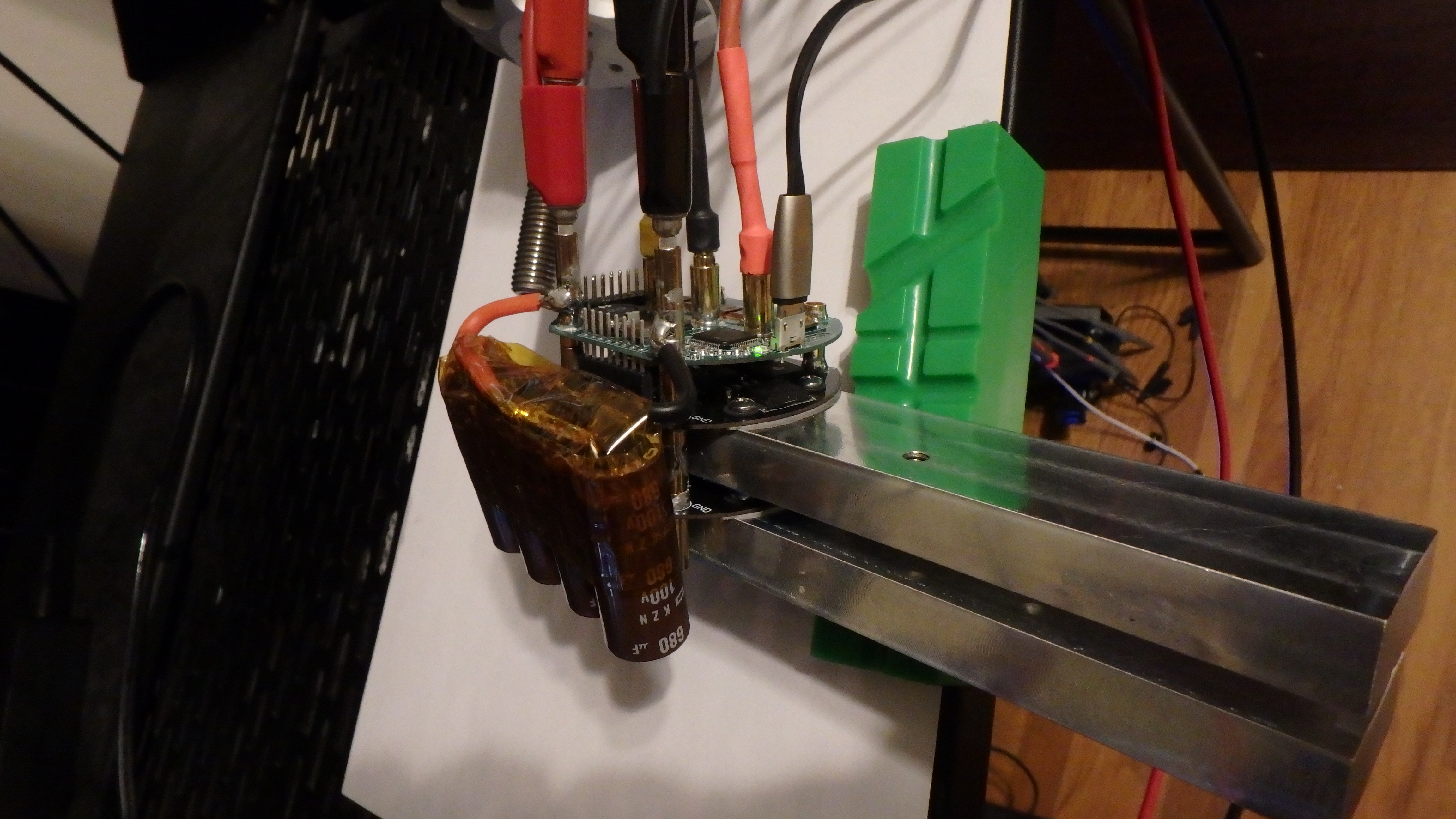
Switching Transients:
The impedance to the power caps is a little higher than in a typical ESC layout (that part was not well thought out ). Plus I don’t have enough ceramic caps due to space constraints. So have to switch a little slower to prevent large switching transients, which heats up the fets. The transient peaks under load right now are Vbatt+10V with no ringing. I could eliminate them by switching even slower but it would make the fets hotter.
Heating of the FETs
There is no heat sink mounting provisions on this board due to space constraints (also not well thought out ). The fets have dense thermal vias to pads on the back of the board, but that only works if there is a milled heat-sink or good airflow over the board. I have a thermal camera on it during testing. Highest I have seen it is 115. The datasheet claims the die temp can get up to 175, which is probably 150 on the transistor case, so maybe I am being too cautious by keeping it down below 115.
Rev 1 is probably not a significant gain over a typical VESC, though for sure it wouldn’t blow out its DRV and dump you into the water. The fact that its a VESC4 and the limitations of the circular form factor cause other issues that limit the power below what is necessary for this task. I think the more experienced members here suspected this might be the case.
The new version has a much better chance of working out. The prototypes are coming next week and I am very excited to test them (also nervous that I mucked up the board layout)!
New boards are here! New test motor is here! Very happy with the performance!
SM-1206 Rev A. 55 seconds test. 48Vin, 51Ain, 155A motor, 77C FET temp, 40% throttle, 2.1 Shaft HP. BLDC mode with current control. Noise at the end is the motor shaft coupling slipping, and I had to end the test.
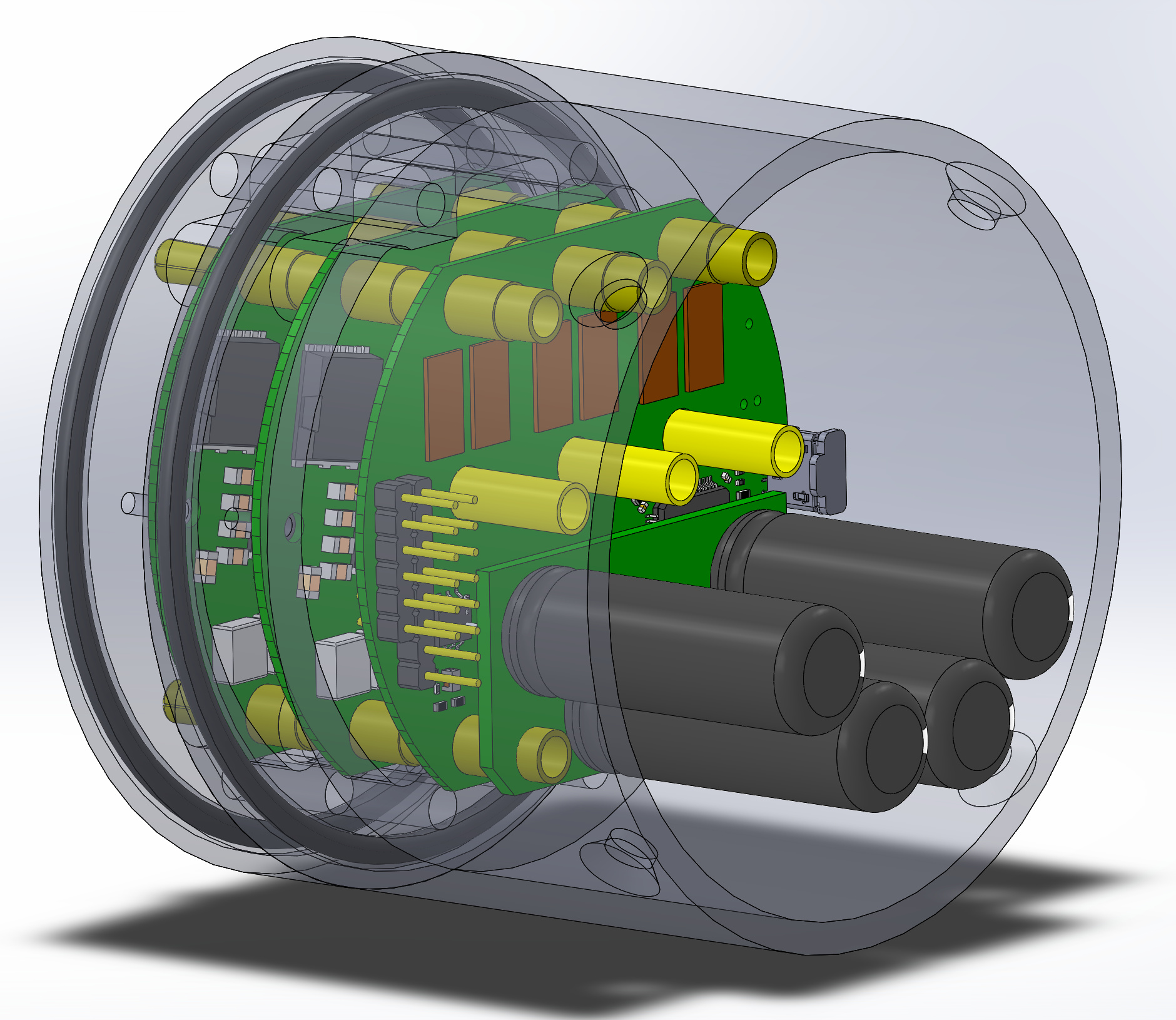
This is my current concept for the mechanical integration. I will need input to make the mechanical setup something that works with a wide variety of e-foil and jet-board thruster setups. The final assembly includes custom male-female bullets for stacking, and a capacitor board.
It seems that creating an apparatus to test a circuit board is significantly more difficult than creating the board itself. The latest drama is the shaft coupling is slipping above 6lbft (~150A), so I need to put the shaft back under the mill to add a keyway so I can push it harder.
Apparatus problems aside, this board has no trouble with 155A. I bet it would handle 200A for a 10-20 seconds, though that test will have to wait for next week. The temperature sensor is next to the FETs on the first switch module, and follows the thermal camera, so it seems good for safety and preventing fires.
The switch modules are designed to be stackable. This is TWO modules. If I added another switch module, we should expect 50% better performance. I would recommend people to use a number of switch modules based on application:
Smaller people who use the VESC now but wish they had something better: 1 switch module
The main pro of electronics in the water is infinite cooling. Common themes on this forum about overheating ESCs catching fire in the battery case, elaborate setups to keep the ESC cool, and other issues with having an air cooled ESC in a watertight compartment.
Another big pro is current control mode in the VESC software. When motor speed matches the PWM duty, the motor draws very little current. If the motor speed does not match the PWM duty, electric current will flow, causing torque, causing motor acceleration. If these currents grow too large, or last too long, the ESC or the motor can blow up.
Most hobby ESCs translate operator throttle command directly to PWM duty. For cost reasons, they do not measure motor current. Few hobby applications (cars, boats, planes) have enough mass that the motor speed and PWM duty can be different for long periods of time. It’s different when there is a human-sized mass involved like on a skateboard or bicycle or electric surfboard. In these cases, you must monitor current and control duty to prevent over-current and fire. The VESC software is designed for this.
Cons are that you must seal the electronics somehow. Ideally this would not be a brick of plastic.
I would like to create a sort of common interface to the nose/mast mount and the motor. Everyone here is a DIYer, so I don’t want to force people to a particular design, but it will be helpful to have a sort of electronics package which anyone can adapt to their specific design. I’ll need input and help from others to design something that can be acceptable to the group.


 ). Plus I don’t have enough ceramic caps due to space constraints. So have to switch a little slower to prevent large switching transients, which heats up the fets. The transient peaks under load right now are Vbatt+10V with no ringing. I could eliminate them by switching even slower but it would make the fets hotter.
 ). The fets have dense thermal vias to pads on the back of the board, but that only works if there is a milled heat-sink or good airflow over the board. I have a thermal camera on it during testing. Highest I have seen it is 115. The datasheet claims the die temp can get up to 175, which is probably 150 on the transistor case, so maybe I am being too cautious by keeping it down below 115.
