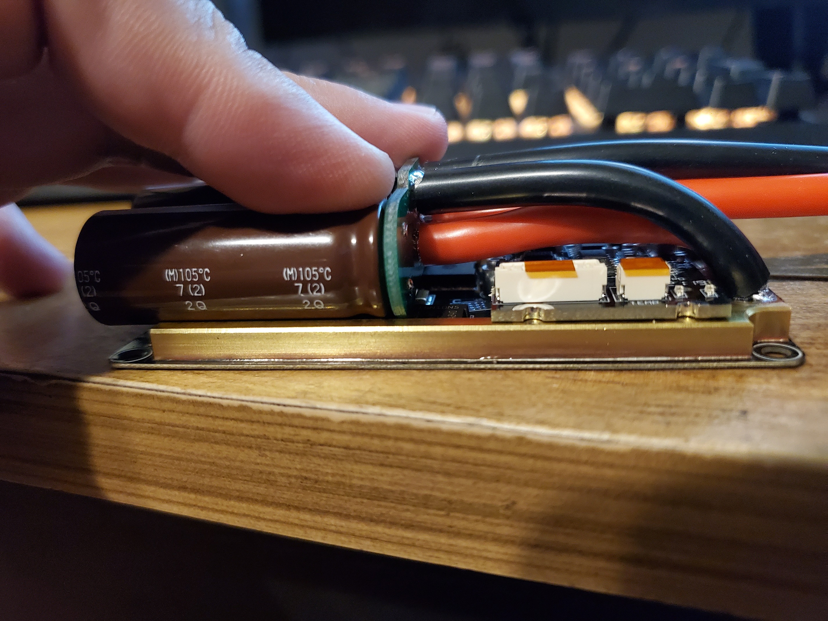
The capacitor board is indeed a weak point, one of the caps dissoldered under mechanical stress. That happened before i added the 3x1.2mF to the board directly, and it was my motivation. Tomorrow i will get some new plugs and hopefully also leads to enhance the input section. I also would like to protect the caps against overheating, so i would like to put an NTC to them. Which type do i need?
Some people ask me if its fun to drive with 18-22kmph speed. I have this conclusion at the moment:
In the beginning: Sure, you need to train to drive curves and find your course and estimate the velocity of others.
After learning: If you have calm water, no, it is not challenging anymore. Now you should try waves or choppy water. There you always find challenges, even on the river Main. Its hard to maintain full control and the reaction must be quick not to fall. Yes, that is sporty and its fun.
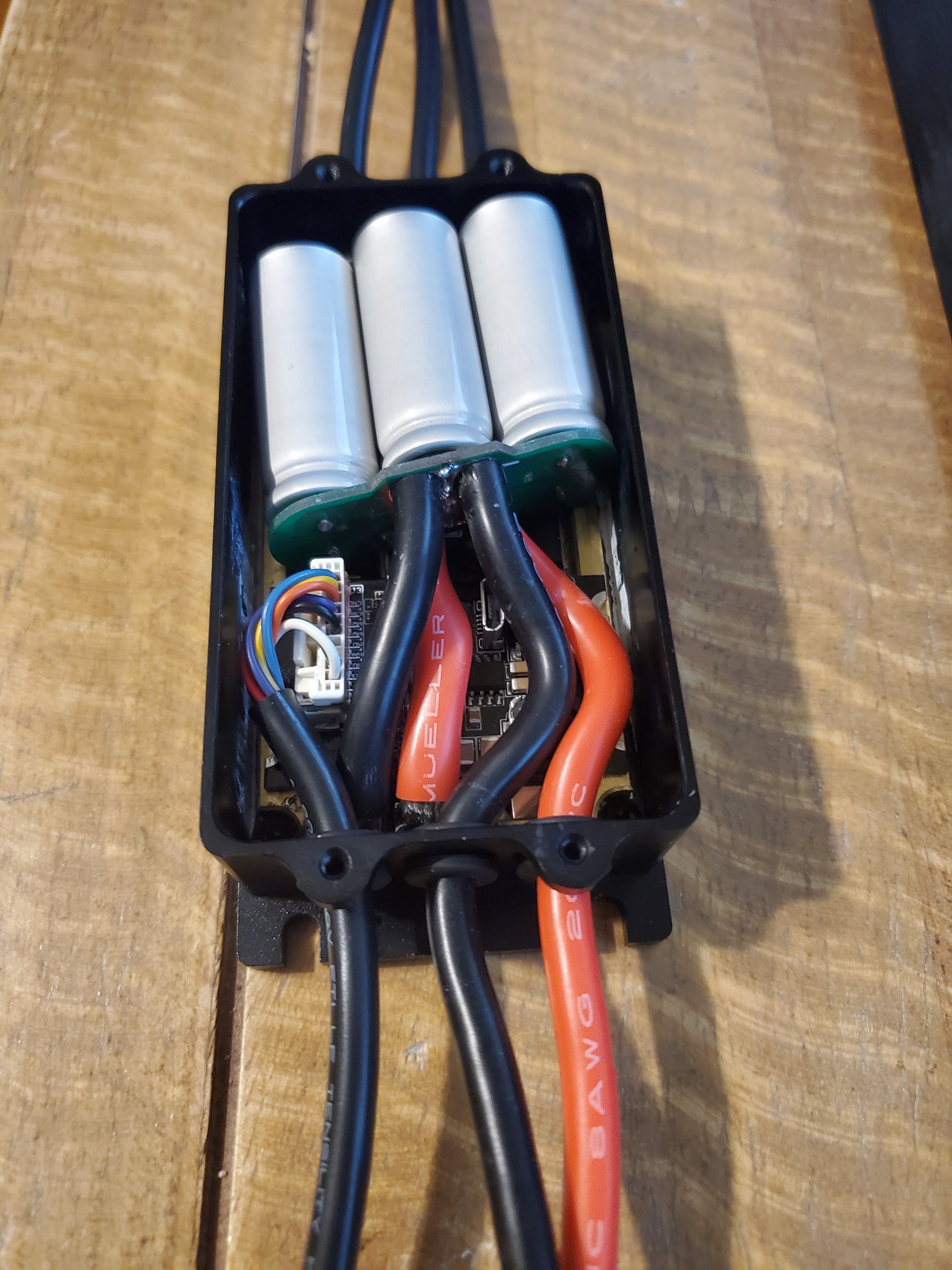
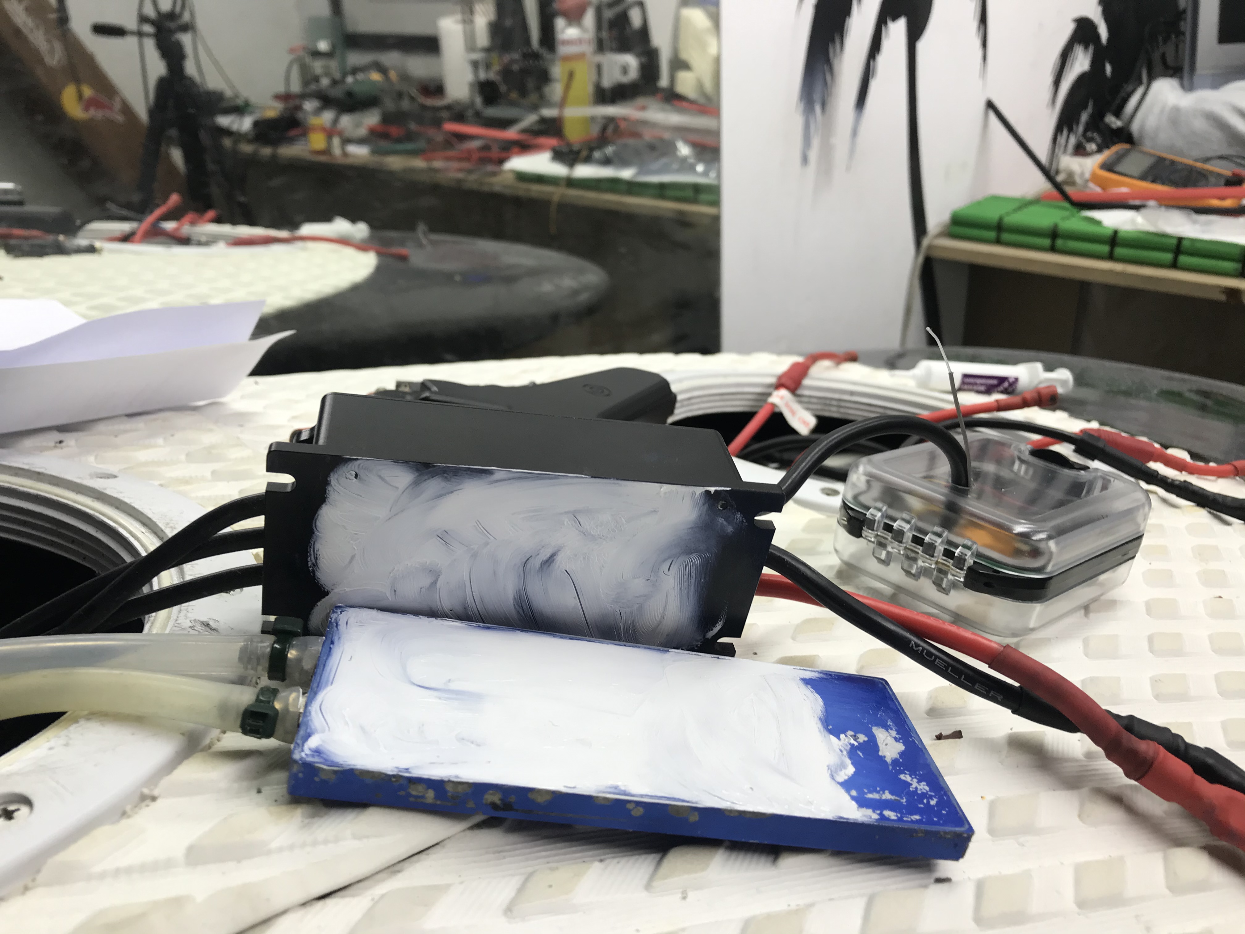
I tested a new capacitor board sample today with DC current. 2 layer board, 1oz copper, 3x 1200uF nichicon capacitors, with 8awg wire in and out, and a little dab of solder between in and out to help conduction.
It looks like 90A is ok for continuous use, though things do get hot. 125A is ok for a minute or two. At 125A, even the 8awg wires get over 100C after a minute. That’s just going to be a hard limit for the wire size and this class of motor controller. Higher than 125A input can’t be maintained without upgrading EVERYTHING: batteries, cables, heat sink, all of it.
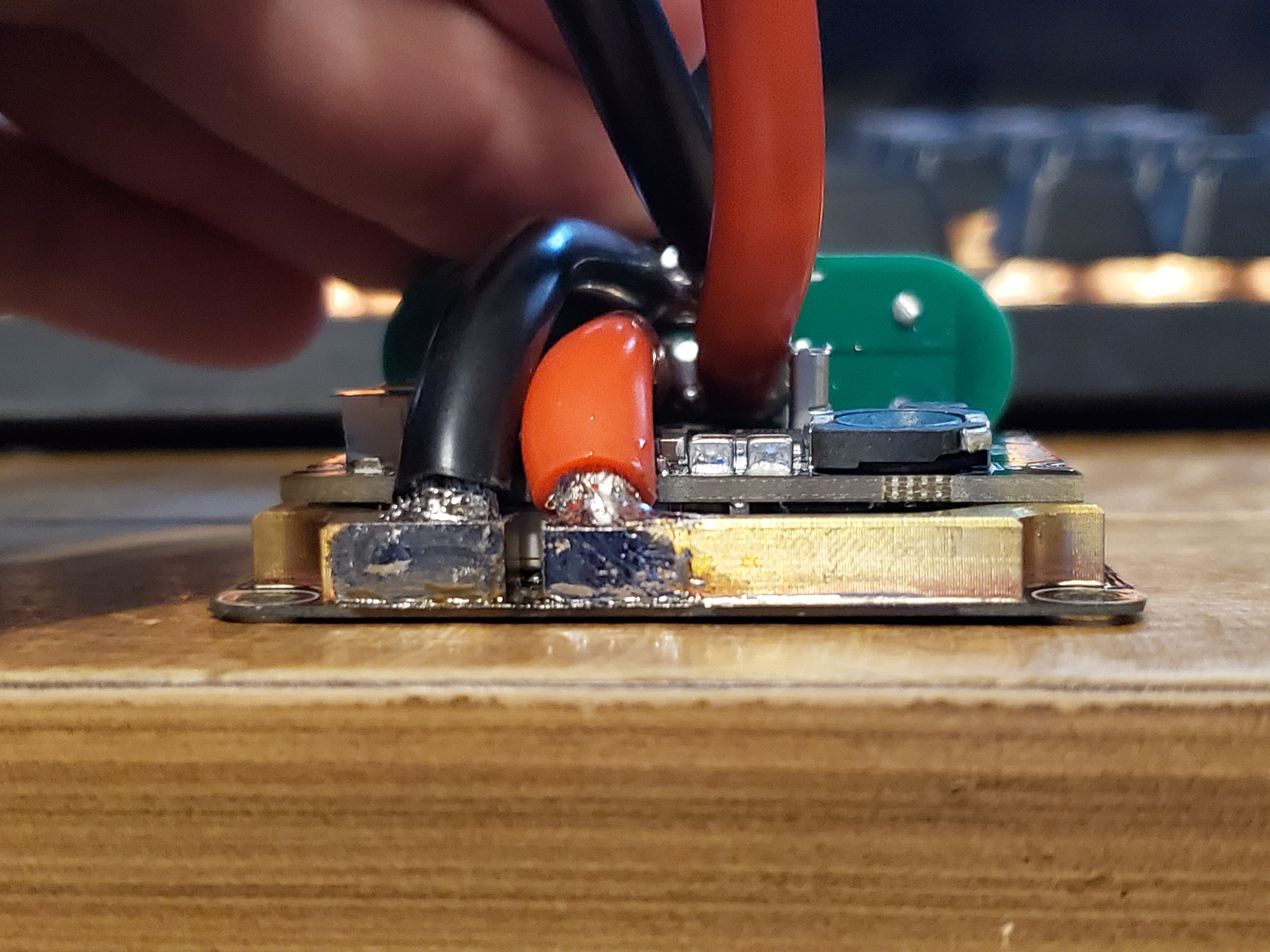
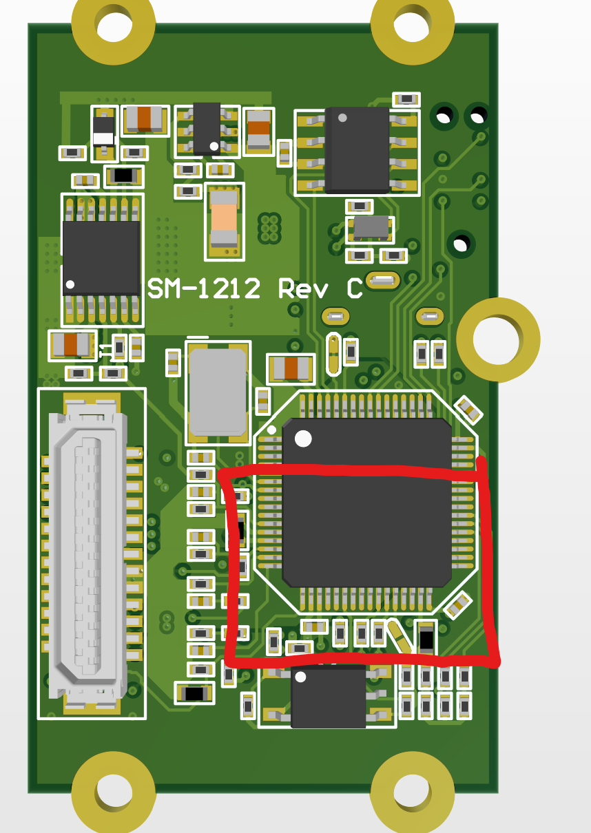
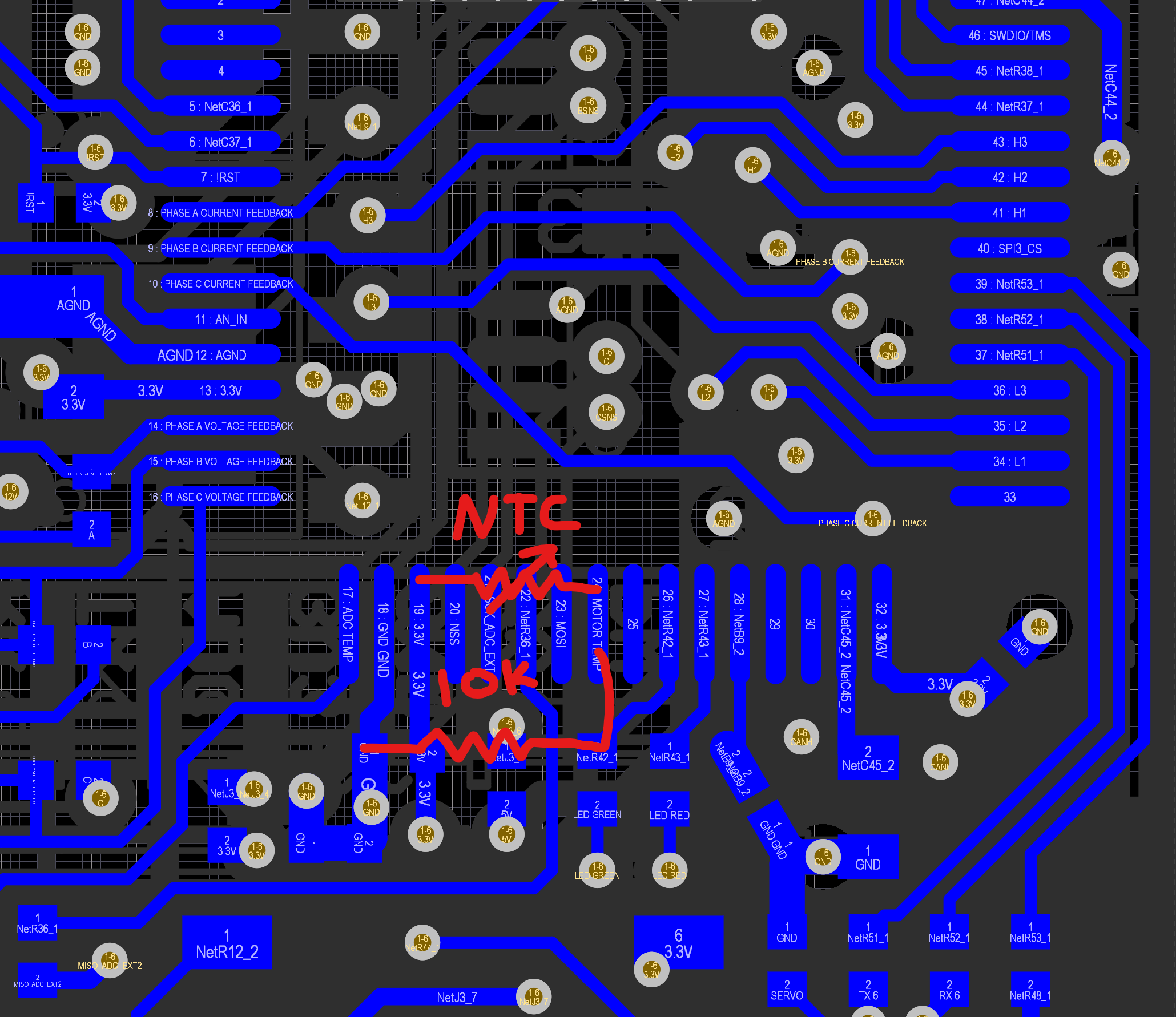
If you want to add an external temp, you’ll likely need a fine soldering tip and a microscope. I didn’t include any of the pieces on the layout so it’s an all jumper wire task. It’s on the bottom side of the logic board also, so…
For the divider, you will need a 10k resistor from motor temp input to ground, and an NTC thermister like murata NXRT15XH103FA1B040 from 3.3V to motor temp input.
I also might need to add something to the hw config file to make it work right, it would be copying the equation for the board temp sense.
ok, i will not follow this plan about additional temperature any more since i would expose the most sensitive part, the 3V supply of the processor to a suspicious risk of being shorted or disturbed in some way. I do not want to sacrifice the integrity of the system i have built up, so i am doing small, controlled steps.
And i never want to destroy something working but instead add and swap something.
In this case, i would like to have the 10k resistor, which limits the current out of the 3V reference voltage, to be on the PCB. So the variation of the outside load does not influence the 3V reference so much. Instead the ref voltage is going outside unprotected. Did i miss something?
I already ordered 10 new logic boards so there won’t be a way to get an external temp on this or the next revision without some high level craftwork. The life of an EE: make a design, wait 2 months for the assemblies to arrive, and find out what you should have added to the next build 2 weeks before it gets here.
I would need to add the divider circuit and a second connector to do this measurement. It’s not a bad idea for the next revision. I think the new size logic board has the space.
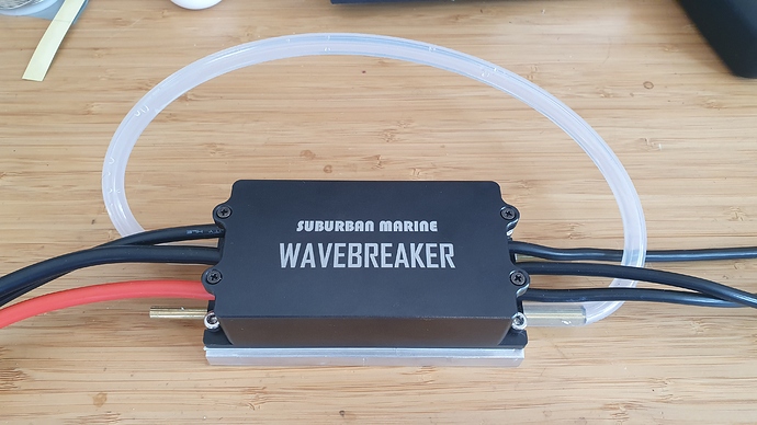
Here is the first test of the boxed version in FOC mode:
The boxed design would be used on a bike, or a (ridiculously overpowered) skateboard or scooter. The wiring has grommets to help make it water resistant. The design concept is to have all the heat come off the heat spreader on the bottom. There is not much thermal mass in just the heat spreader, so some air is used to cool it down in the video.
Looks quite promising, but I’m wondering if you can mount it in the propulsion unit, because it is not perfect to mount in a tube.
Or did I miss something and this is not the plan now?
That’s a lot tighter, that’s perfect.
If I can get one of these I will cut a hole in the metal tube the size of the vesc and weld a flat metal in it, to mount the vesc direct to the outside water cooled plate.
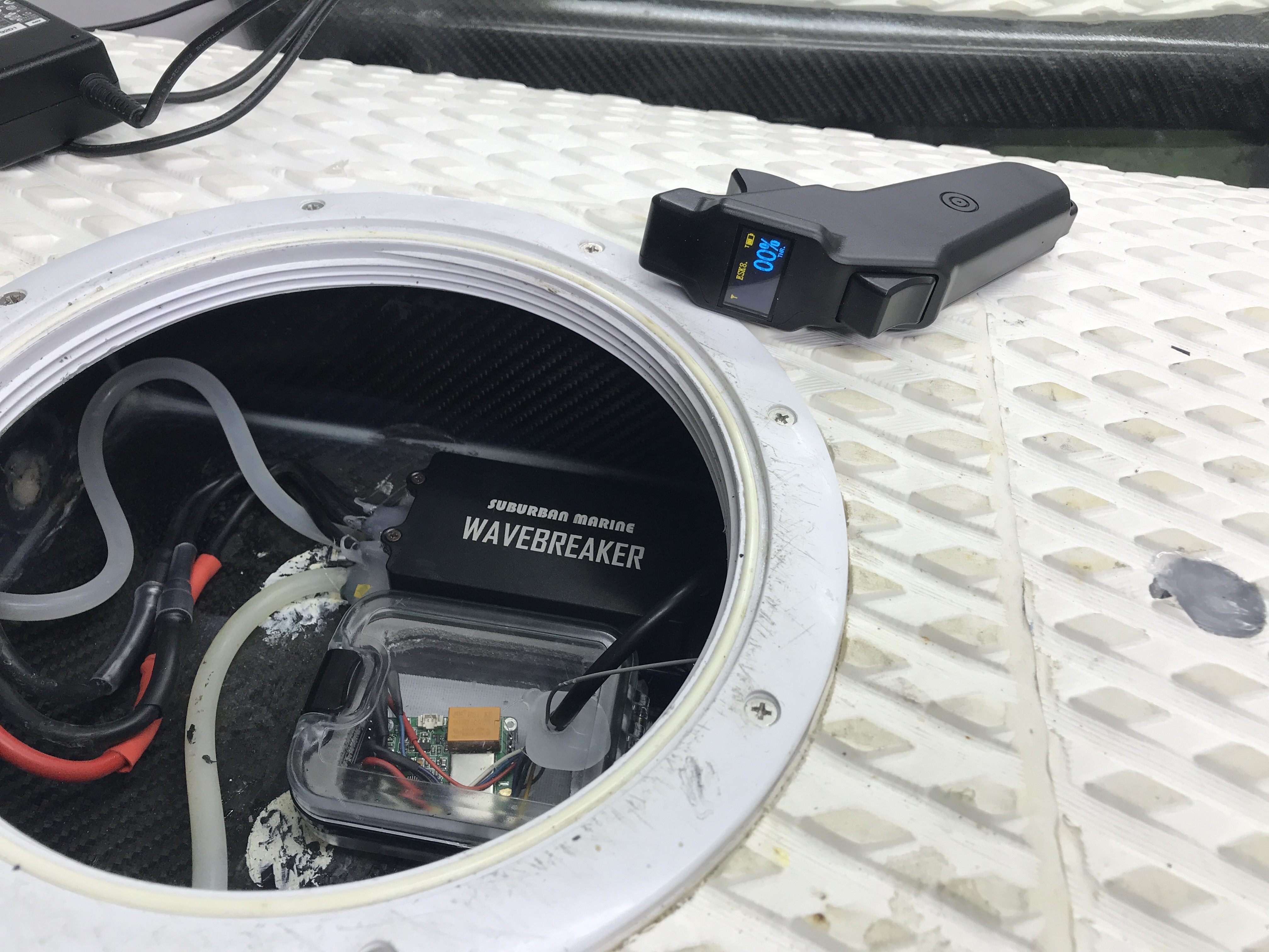
Here is a pic of a unit that Nick sent me for testing. I have attached it to one of my custom watercooled heatsinks. I have the Metr pro so will be able to get full data from this and the 65161 120KV motor it will be tested on.
I had a successful first test with @nickw1881’s VESC today. No logs yet but the metr is in the mail. I could monitor temp/A/V on the remote and I didn’t see it much above 40C during our 2x 40min sessions today. I had to remove Nick’s pretty VESC case to fit it into an IP68 aluminum case which is mounted on top of the mast. Am very happy with that new setup so far. @peter’s 80mm direct drive prototype motor (Any interest in custom Direct Drive Inrunner - #45 by overdrive - Propulsion System (Motor, Gears) - FOIL.zone) is a quiet beast with that VESC in FOC mode. I will post more build details and logs when I get my metr.
I’m testing a similar setup, Nick ESC and maytech motor, first thanks to Nick for your ESC and help to configure. Well, I think my data is good but I have problems in 30-40min of ride. My esc stops and I need restart to continue, I dont have any problems with Maytech ESC in the same setup. I agree Merten, this FOC setup is incredible silent.
Not sure what is going on with @virus board. My guess is software issues with FOC and his particular motor. There are 6 other esc out there with various other forum members but @virus unit was not tested with this batch, and so I can’t say for sure it doesnt have a hw problem.
Several people have asked about getting more of these, and here are my thoughts: I designed for small size, packing in the parts as densely as I could. Because of this trade, the cost of these units is around $250. 3 pcb, billet aluminum case, cnc brass busbar, xt90 pair, and that doesnt count labor to integrate it which is about 30min per board once ai am practiced. Then in every batch one of them doesnt work, there is shipping to pay etc. This is all to say the design itself is too expensive since no one wants to pay over $300 for an esc when flipsky is selling them for $200.
Then, VESC software doesnt work for every design as we have seen in some cases. How could I recommend someone spend significantly more money on an esc when it may not work in their setup?
Maybe it makes sense to make a different design, one that is cheaper and easier to build. Maybe it’s a little bigger, but has the same heat via concept. That seems to work really well. I’d keep the busbar as well. But then the cost of a new dev effort is prohibitive at this point. Maybe the existing design is good enough (after I beef up the input capacitor board).
Following up with my train of thought, I designed a board per @pacificmeister specifications to fit in the enclosure he picked out. He mounts his motor controller on top of the mast in an IP68 3.5x4.5x2.25 enclosure. Since it is in the water when not foiling, it always starts cool, and then it can conduct heat down the mast when foiling. To simulate good conduction to the water, I used a large aluminum heat sink.
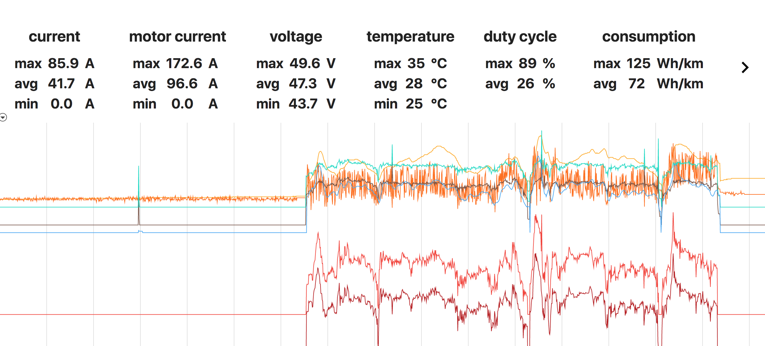
Here is my first test of this design at 200A motor (150A battery) for 30 seconds:
This design can handle 48V and 200A to the motor, but is much cheaper and easier to make than the last design. I believe I can sell this for $300.
 so there won’t be a way to get an external temp on this or the next revision without some high level craftwork. The life of an EE: make a design, wait 2 months for the assemblies to arrive, and find out what you should have added to the next build 2 weeks before it gets here.