Why not split the two parts where the mast is widest?
those parts are clean 
You should really try to close that gap as much as possible.
If you keep a gap too big, as soon as you start screwing, you’ll end up stressing the part in its weakest direction and layers are likely to keep splitting.
To get stronger parts, i think it’s better to increase the number of walls than to increase infill, especially that those parts don’t need to be waterproof anyway.
May be the simplest is to measure the distance between the bottom surface of the red part and the top of the mast hole. Then you divide the gap by the previous distance to get the % you need to add in the long axis. that will slightly deform the angled contact between the 2 parts, but at least the gap will be reduced and your parts will stay strong.
Of course, best option is to modify the file Fusion360 is free for home use…
The screw head is held in the red part, goes thru the green and screws into the motor for a complete unit, splitting at the widest will cause me to find longer screws which are kinda hard to find.
The screw length is one reason, but there is another one:
The split at the bottom allows the front part to kind of stay in place when you do the assembly.
The screws are going through both parts and screwing into the motor, so the assembly sequence is to put the front part around the wires exiting the mast, pass the wires thought the intermediate part and connect the motor.
To either put shrink tubing or electrical tape on the connections comfortably, you need the wires to be long enough.
Once that’s done, you can fold the wires on the other side of the mast and bring the intermediate part and the motor in the right place to screw it all together.
The longer front part makes the whole operation a lot easier
1 Like
@Halifax21, I had a similar clamp part.
After 3 or 4 times, sharp edges of mast cut my 3d printed part ( with vibration also probably)
I found solution with adding bended aluminum sheet, after that problem was solve
Initial part and alu bended sheet :
Actual shape of 3d printed part :
1 Like
i used that one:
but anything that will screw in the plastic with a barb fitting on the other side should work ![]()
2 Likes
@Mat How did you make your 3d printer make those timelapses!? So much cooler than my GoPro mounted on the side of my printer! haha.
Also, can you list the materials you used to epoxy your motor? I am going to make a shopping list as I’m going to go through the whole procedure myself. Any tips and tricks would be great too! Fingers crossed!
1 Like
So for the timelapse:
I add a small dummy piece in one corner in the back (red arrow)
So after each layer on the main part, the head has to go to the back for the layer on the dummy one.
When it gets there, the magnets attached to the main arm (yellow arrow) pass in front of a magnetic switch.
It send a signal to a microcontroller (blue arrow).
The microcontroller then use an infrared LED (green arrow) to tell the camera to take a picture (kind of like a TV remote).
I did the first few tests changing the camera battery every hour as the camera has to stay on to not lose focus… but when doing 12 hours prints it becomes painful, so I found a adapter to keep it plugged straight to the wall …
To epoxy the motor, i used resin research epoxy, same as for my surfboards.
On the rotor side, I used a piece of acrylic tube that fits right inside as I had it on hand, but any sheet of plastic stiff enough to make a “wall” to cast the resin in the gaps between the magnets should be good. I also used some clay to close the bottom.
on the stator side, i brushed the epoxy on the winding, used liquid tape on the leads to keep some flexibility and some adhesive lined shrink tubing.
@Vicdes2 wrote a clean guide: google doc
3 Likes
Hey Guys, having recently switched from an inrunner/reisenauer combination to the 80100 direct drive I gotta say I’m a bit disappointed. Apart from the simplicity its significantly slower, sucks way more juice from the batteries and as a result the pack runs very hot. Performance begins well buts drops off to almost unfoilable when the pack hits 37% which goes against the grain with lithium batteries doesn’t it? I thought they were either on or off! I’ve gone from 70 to 15min run time on a 2kw 18650 setup!
Forgot to mention I’m running 7 1/4 x 5 A prop.
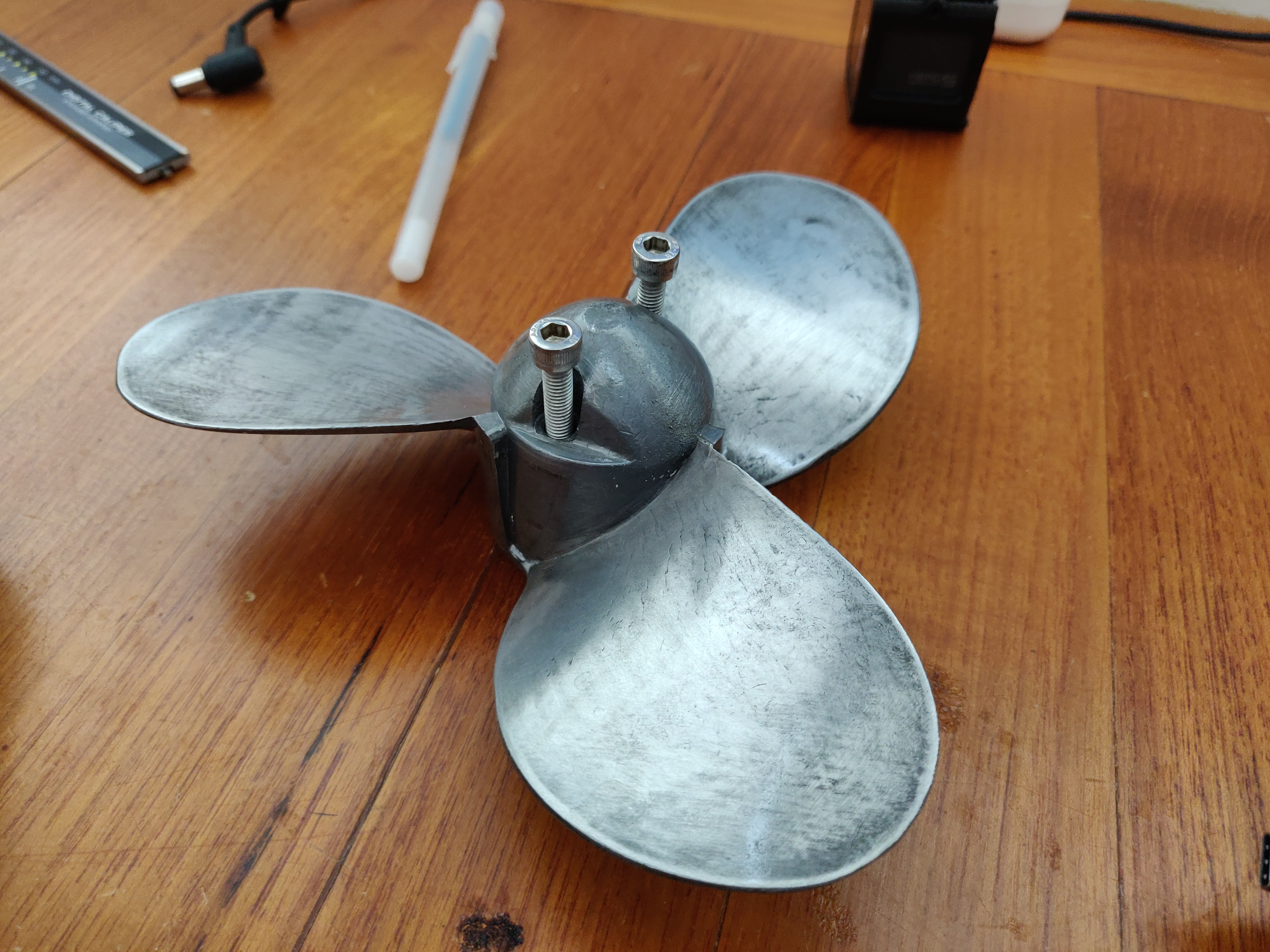
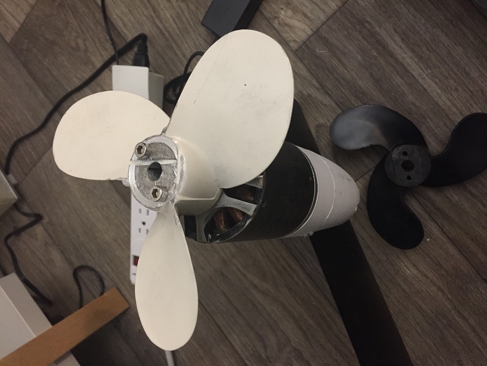
I think it causes a poor quality propeller (also a tube)! Can you show the photo of the propeller and tell what the material is?
Can you tell us more about configuration:
What inrunner , size , kv
Gearbox 5:1 or 6:1?
What kv outrunner?
What cells ? (30q 25r…) And configuration 12s16?
Same propeller is used in both setup?
Lithium is on off but not linear , with temp if you draw 2x more amp you can loose 3x running time , 37% is with voltage drop or actual capacity measured ( you cannot Foil because you don’t enough rpm or the battery cannot give the amp at start …)
That seems very low indeed.
you mean 2KWh? right?
i have 2 6s 16Ah batteries so around 700 Wh, and get a bit more than 20 minutes out of it.
From what i measured i was using 50-60 amps with the solas plastic propeller 7.3 x 6.
did you fill the space between the magnets?
did you add a cap on the prop side of the rotor to fill the holes?
those are the 2 things i found were creating the most losses.
How many amps are you pulling and what foil are you using? With the same prop I pull 55 amps to get on foil and 34 to 36 amps foiling. Like Matt said above make sure to fill magnets, etc.
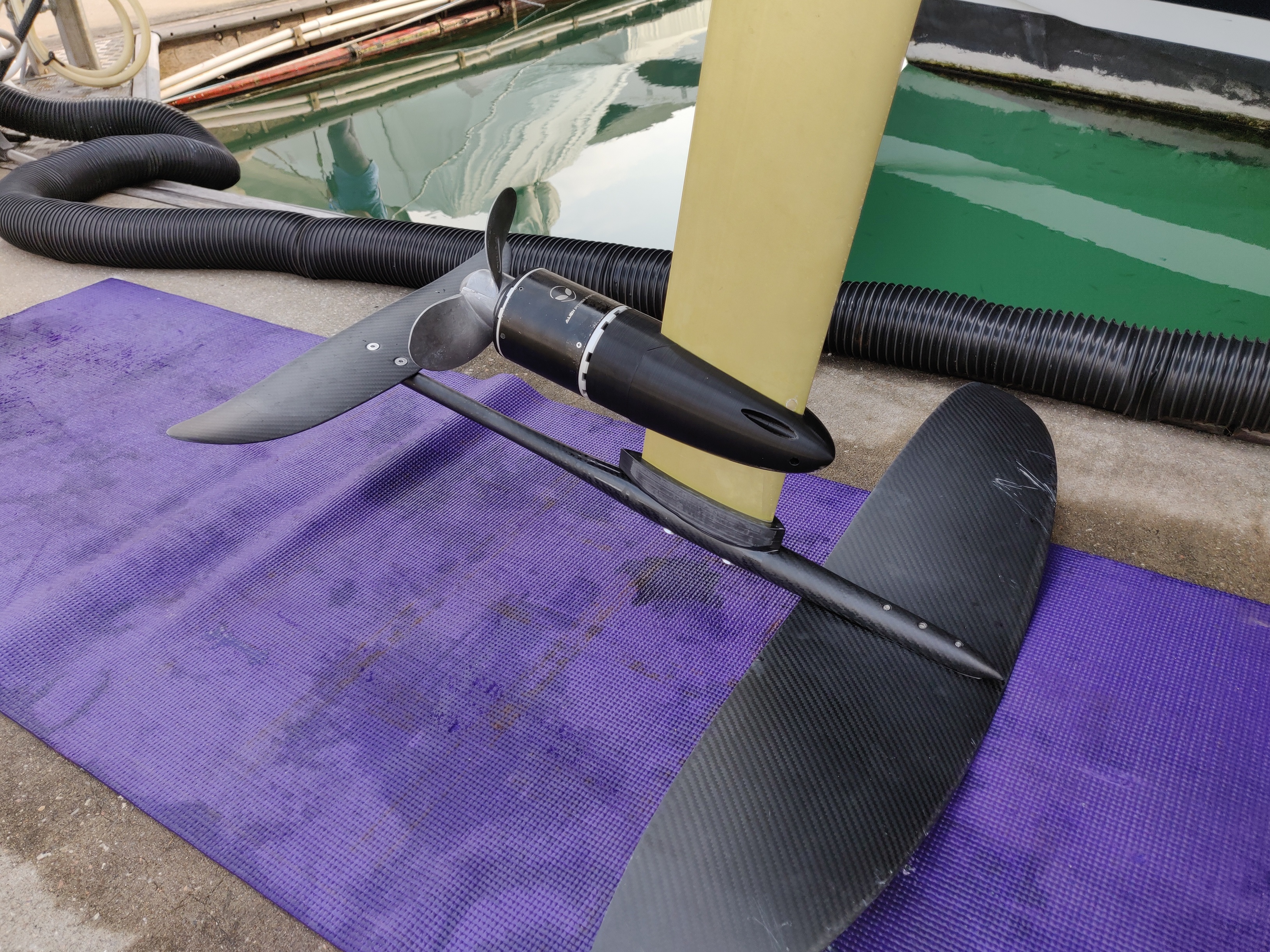
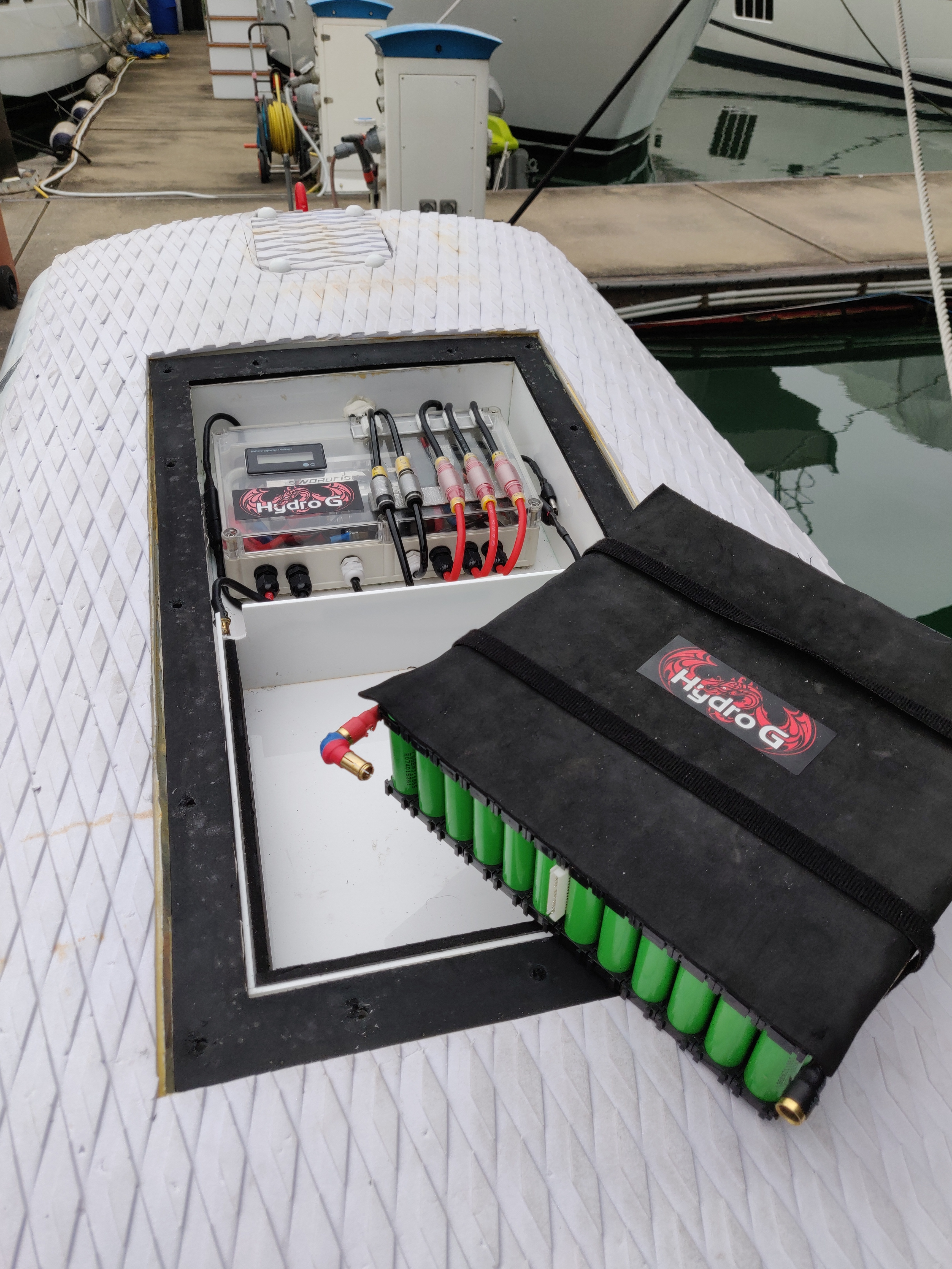
Hey Guys. I’ve attached a few photos for reference. I was running Inrunner 56104 500KV with the reisenauer 6:1 gearbox housed in an aluminium tube, propeller was a 142mm printed parametric prop downloaded from this very site. Battery pack 12S12P LGMJ1 18650. Extremely successful setup, fast 35kph. Cool, Swordfish 300 ESC never got above 36 C (watercooled). Efficient, 70 min endurance. I broke the mast clamp and upon disassembly found water in the pod.
So the new setup is the stock 80100 80KV, filled magnets and end cap using the 7 1/4 5A prop. I cant get my data logger to play along so I don’t know what Amps I’m pulling, I’m guessing a lot because the battery is significantly hotter than the previous setup. When I shut down after the last 15min ride the battery was indicating 37% (0% being 36V), the last 200m was off the foil as I couldn’t get enough speed. What speed are you guys getting? I cant get above 24kph when foiling.
!

3 Likes
nice built, it is hard to compare you change motor and propeller, what i will try
- try the other first propeller (which must have more pitch)
i think most setup here use lipo so the voltage is higher than the 18650 and 24km/h with this propeller and 18650 looks correct to me
- have you change setting in esc? the outrunner needs more frequency and timing… 22-44 and maybe 15°
With a 5" pitch propeller you will be around 25km/h with 18650 and 30 with lipo
At 37% so around 3,44v /cells you should have enough speed to fly so my guess is that the motor pulls to much amp and battery doesn’t give enough juice : this propeller has to much thrust at low rpm with its area , it is for a boat at first , try the solas ( even cut it and re shape the blade ,see my post ) , 30km/h and less amp should possible , or plug just the first printed propeller
Propeller: Good material, blade shape is not very suitable, large diameter and large pitch. Although MAT uses a plastic propeller (https://efoil.builders/uploads/default/optimized/2X/2/22fb77b91e22a123a1c8b8851e5a372ea3c9ca16_2_999x750.jpeg), which has a similar pitch, but plastic blades at max RPM partially equalize under water pressure, which will cause the propeller pitch to decrease.