The Telsa way would be the best, but I think that would require more specialised equipment. We will do it caveman-style and have a 150 A fuse at output end and 40A on charge end of the positive busbar.
1 Like
I finally welded my 12s10p pack today, I have a fuse for every cell. Those are much more work! Spot welding those takes time to get it right. If you don‘t plan on a single cell going completly bonkers you can for sure get away without it. Cell fuses would prevent all parallel cells dumping their energy into a single failed cell. You should also consider that those fuses can increase your losses significantly. Especially at higher currents as my Pack is quite tiny and thus is designed for 10A per cell.
1 Like
I think over my BMS, i think it uses the same cell monitoring circuit (ZLA13). One BMS Fet short circuited during overcurrent shut off. A fuse can do better.
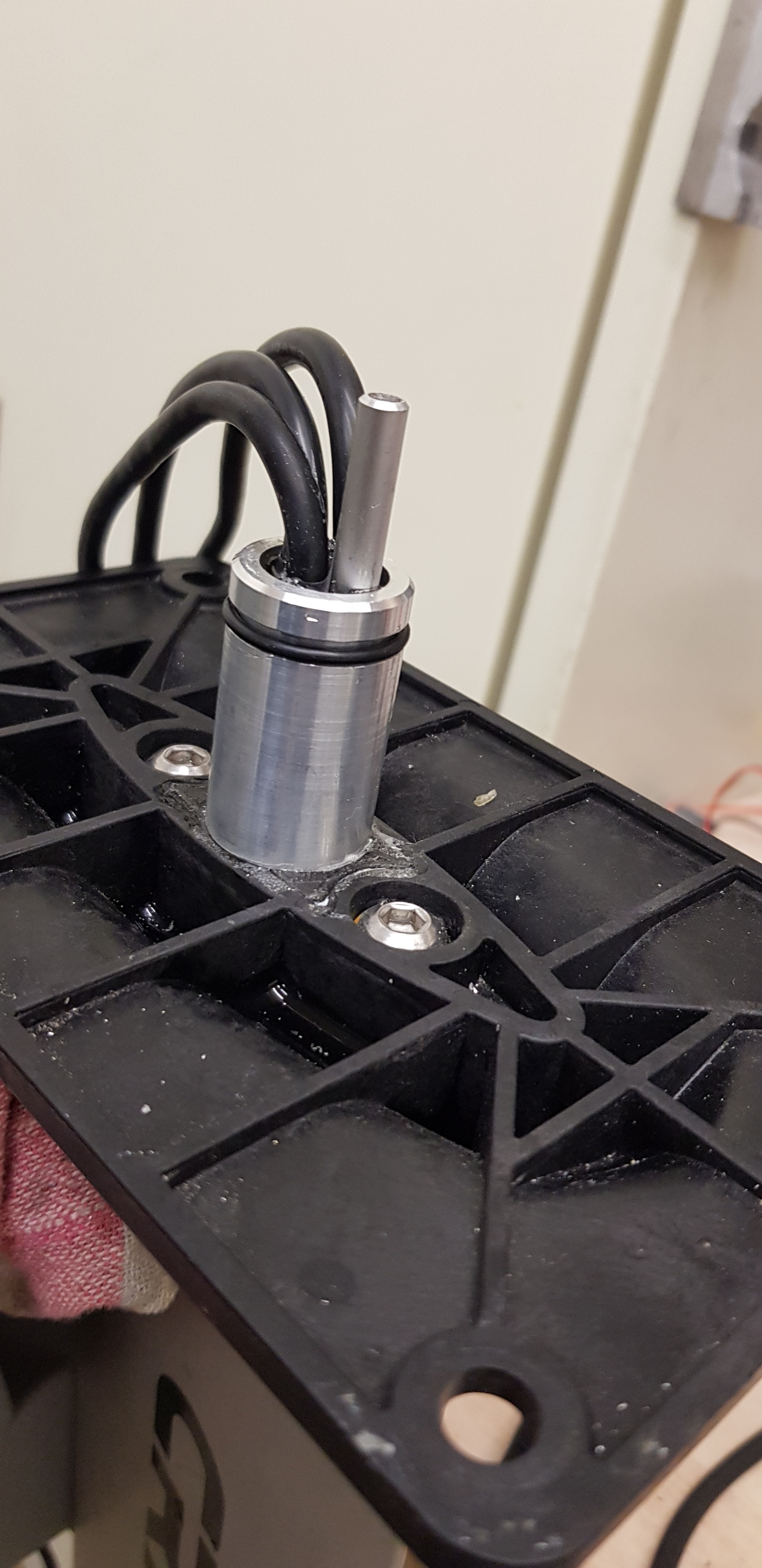
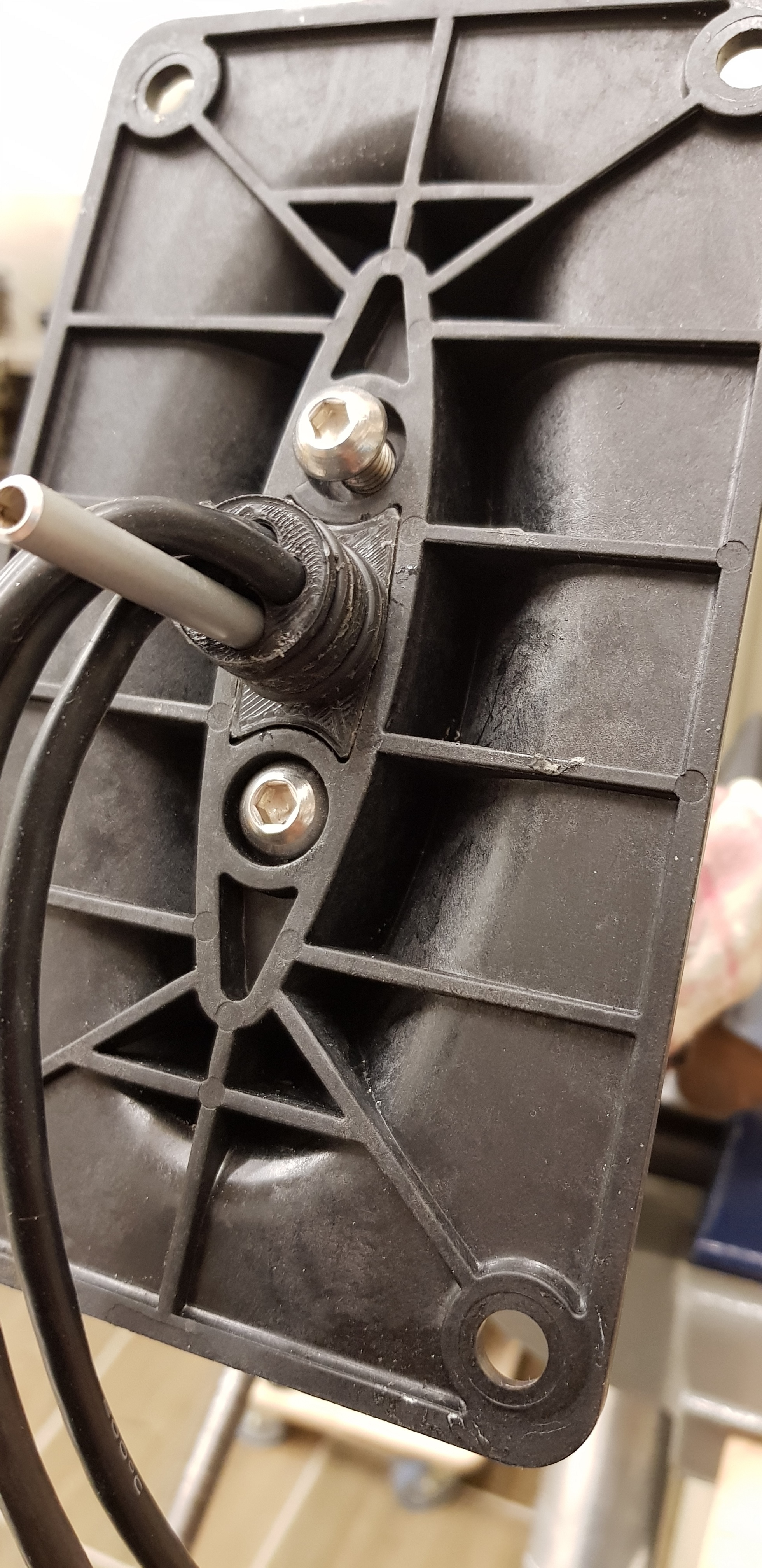
One thing i do not understand: The screws going through the pack are electric conductors. Are they necessary for the mechanical integrity of the isolating plastic sheets? Maybe replace this sensitive plastic by a glass fiber sheet and make the screws from glass fiber plastic as well? I plan to use such material for my cheap 1.4kW 12S 32Ah pack.
Thumbs up!
1 Like
nice build, you didn’t use Insulating Ring paper on positive ?, did you spot weld yourself ?
i was planning to get this : kWeld - DIY battery spot welder kit | keenlab , some people spot weld the fuse with that…
The screws are there to give structural support to the pack itself (black cell holders). They are all insulated with heatshrink and 1mm polycarbonat, but the top/bottom is conductive (and connected=bad). I agree that something non conductiong would be better, but we did not have non conductive rods available at the time of assembly, we will change them to threaded nylon rods. Thanks or the input.
Alexander: it’s standard cells. They came with insulated ring paper, just not visible in the pictures.
Just: The cells are only balanced during charging
Not during discharging. There will be a separate charge input, so the power only goes through the bms during charging.
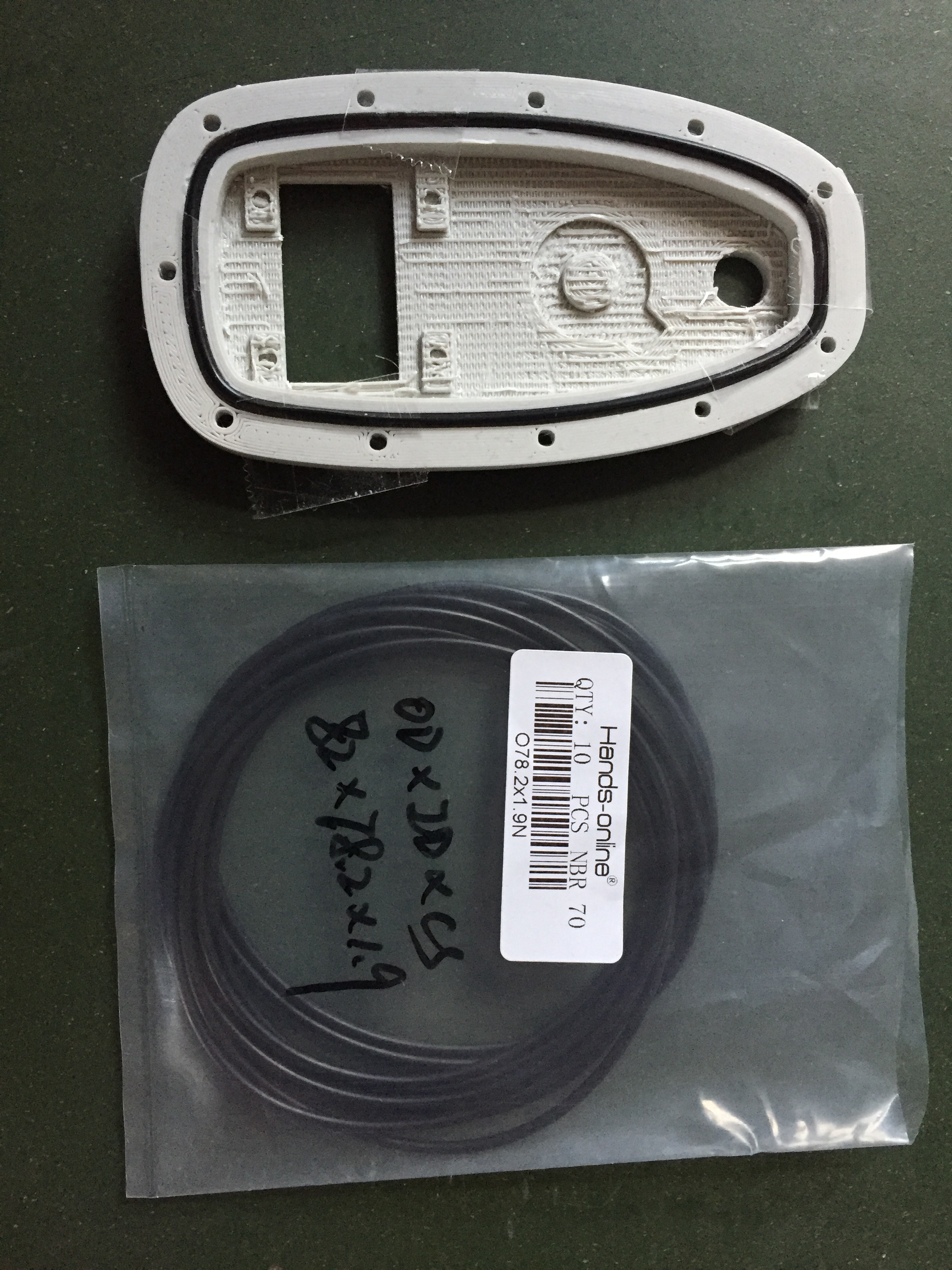
RS-online (from Germany) did not want to sell me their stuff so I couldn’t order the endless 2mm Oring.
I found a suitable closed loop (1.9mm thick) if anyone is interested: https://www.aliexpress.com/item/Oring-Mechanical-Seal-Dichting-Rubber-Ring-Gaskets-thicknes-1-9mm-O-ring-Kit-O-rings-Gasket/32838978245.html?spm=a2g0s.9042311.0.0.Z9d9RY
ID 78.2
6 Likes
Finally got our big battery-pack on the water, gave our board a facelift as well  The battery gives loads of power.
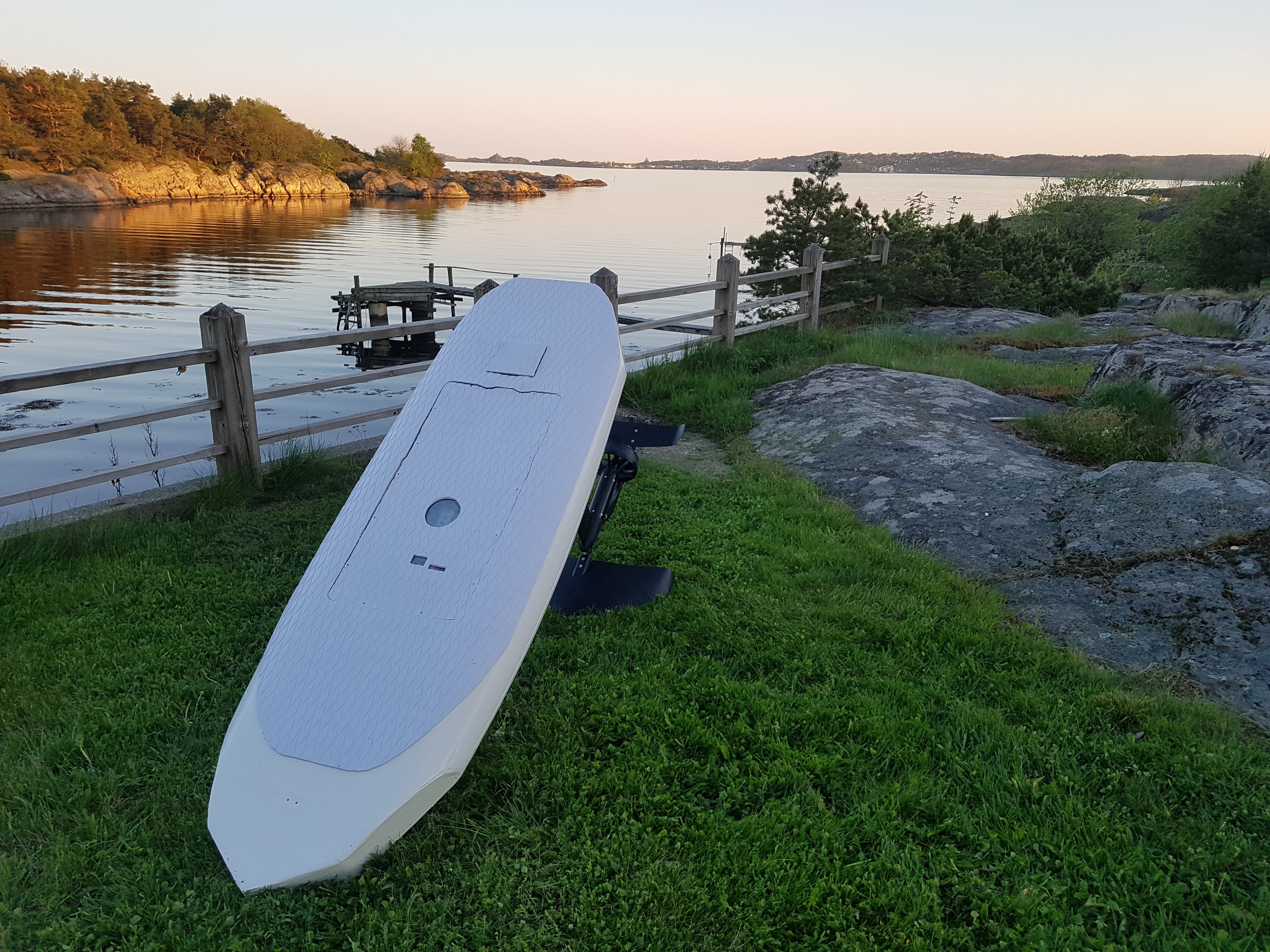
Built a version of the remote we posted earlier in this thread:

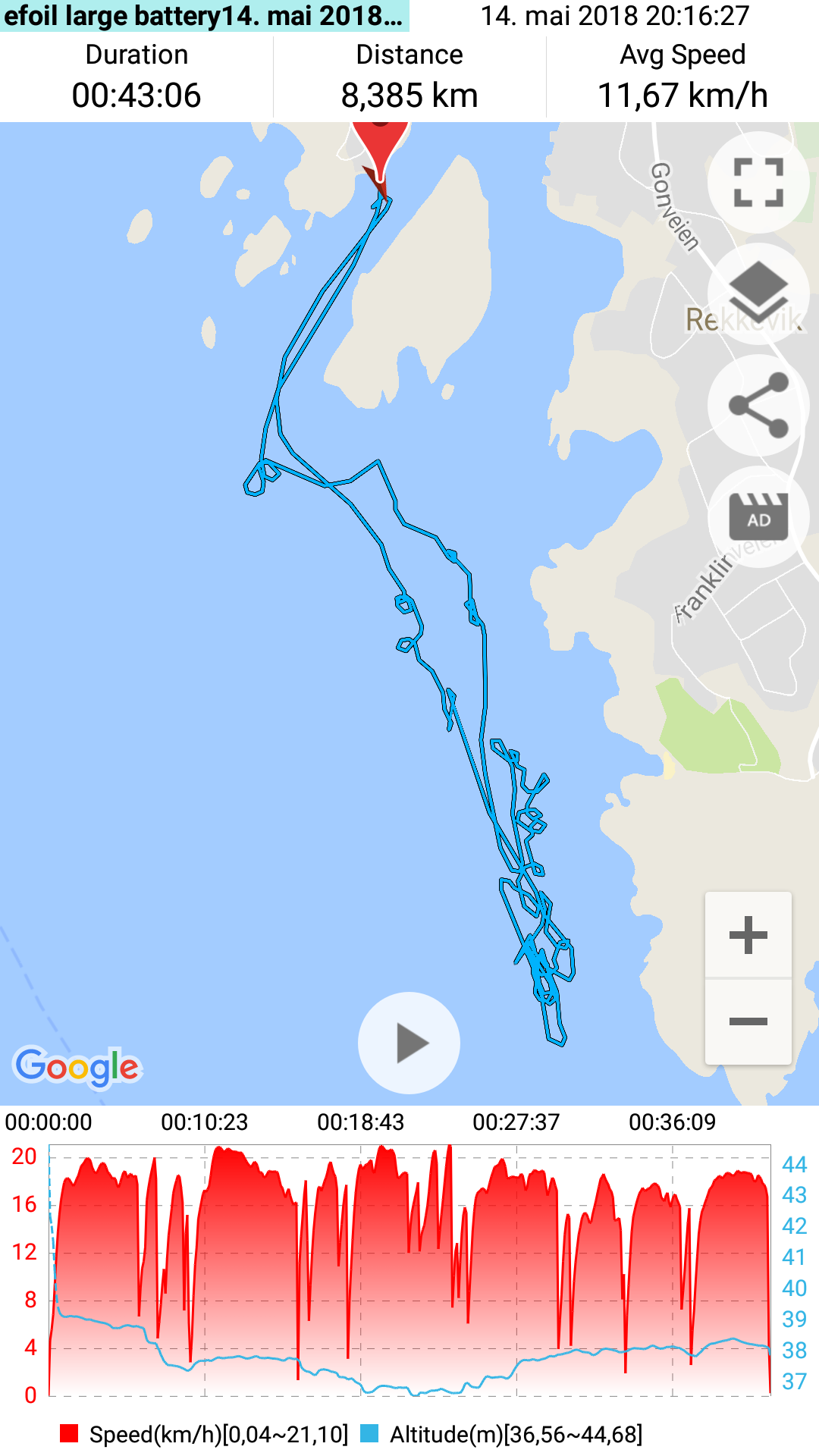
Stats are from the pack used from 50V-44V (12s, we are still gentle with it) and 90 KG rider. Prop are still revision 1, duct is identical as revision one, apart from lower AOA on the accelerating profile.
This ride was a loads of goofing around, sitting on the board with feets in the water etc, so could probably gone for quite a bit longer.
7 Likes
Hello Everyone,
I am having a strange problem: when I press the remote trigger from 0 to 50% of the power my prop is barely turning and in a very jerky movement over 50 % it all goes fine? Any idea what it could be?
I checked for water ingress in my motor pod, I had to drill a hole and no water came out (I will put a screw with an o-ring to close it again)
Also checked the esc box and it was perfectly dry
Mine did this when the insulation on one motor wire burned through and shorted out. Can also happen if a wire from esc to motor comes unplugged. Or a bad esc.
It was my ESC! No clue what broke down, it’s rated 400a and never got more than 200a, always stayed dry and cooled to 40 Celsius??? It’s an Alienpower 400 16s and it worked well for more than 10 hours until this happened and after a few more tried it died.
Now, I will try out with a Flier 320
https://fr.aliexpress.com/item/Flier-new-version-12S-320A-brushless-ESC-for-RC-boat/32750220880.html
Weird. We are still using seaking 130A, it has been running for 40h+ without any issues, we have implemented smooth acceleration to spare the gearbox, but this might help with ESC life as well ?!
I agree, it is strange that some guys are pulling such huge currents! I feel there could be sketchy solder joints somewhere or something along those lines.
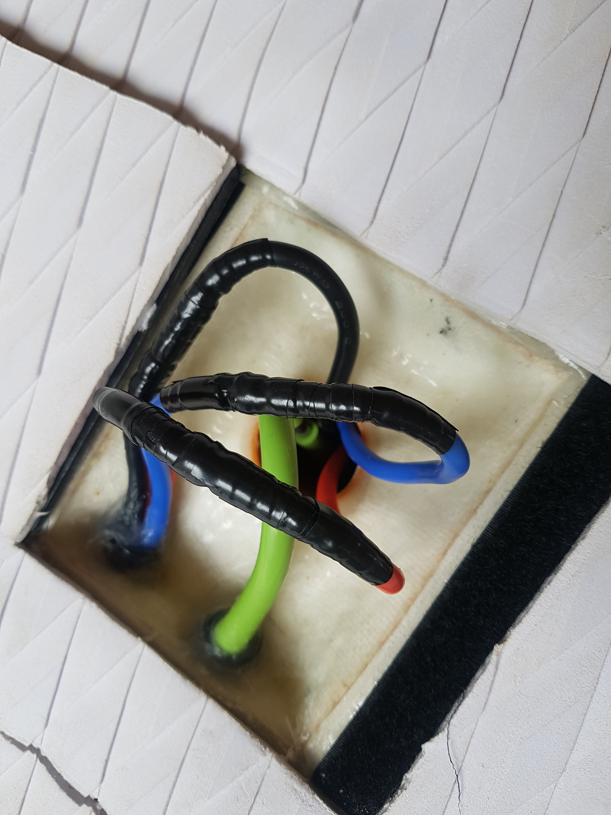
Awsome build and great work! Could you elaborate how you get the connectors from the mast into the ESC box? It looks like you have a pluggable mast design with the connectors in the wet space above the mast. How do you keep the connectors waterproof?
We use regular bullet connectors and quality electric tape that always sticks, even under water (scotch super 88).
Tape is more waterproof than adhesive lined shrinktube on silicone wires, as the adhesive does not stick to silicone, Good tape on the other hand does.
Not a production/user friendly hack, but It works great if you know how to do it! We only take of a small section of tape(5-7cm long) in the middle to take them apart,not all the tape.
Will probably build a quick connector but for now it works good enough.
4 Likes
Hello. I have also done something to plug/unplug the mast. May be it can give you some idea. It’s all waterproof


4 Likes
Looks good  we have something different in mind
Hi Vincent,
Did you have time to try teh Crazyfoil yet?
Hello. Not yet. Got some problems with the motor. And you?
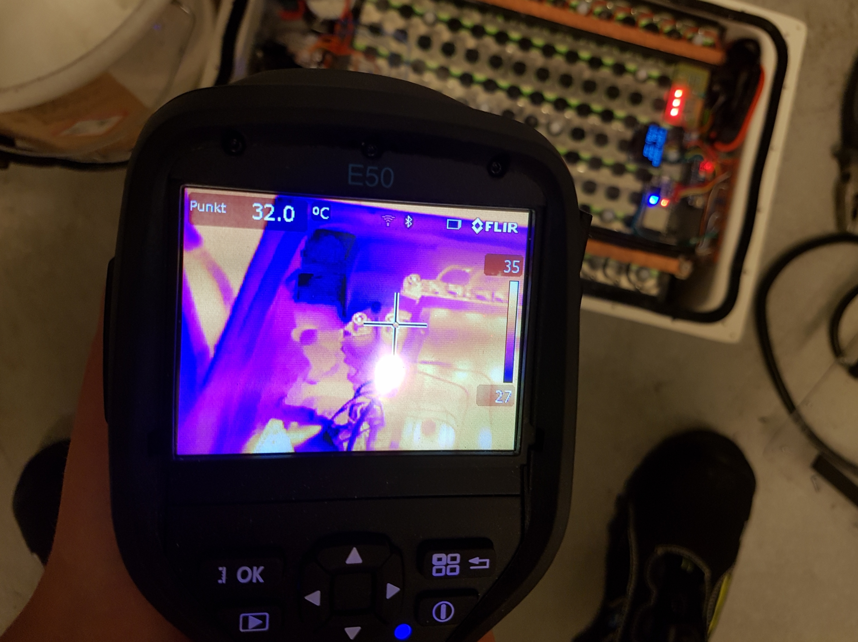
2000W continious discharge of battery pack. No apparent weak points detected. UBEC and relay seems to have highest temp. Smashed copper tube busbar works perfectly!
2 Likes
That is really awesome! What did you use to weld the cells?