Thanks for the Files, I can open the step file but it is not perpendicular and centered to XYZ. I gues I can somehow rotate and move it to the right position. Unfortunately the fusion 360 download link does not work, the file seems to be empty.
In your slicer …Click Edit… Click Place surface on board… Click the surface that you want to be flush to the heat bed… The click centre and arrange
Hi @Hiorth, just wondering, did you do all of your ESC control (acceleration curves etc) via arduino or did you buy a programming box for the ESC and change some settings that way. I’m going to buy my ESC soon and was wondering if I should get a programming box or not worry about it. Thanks 
Hello @Goldy
Yes we use an arduno as the “brains”. Then we can get the curves we like, with just som lines of code.
It depends on if you want to do the controller from scratch or go the RC way. It is also possible to make a arduino buffer between the rc reciver and the ESC. To make slow
2 Likes
5 Likes
Good to hear that! I’m a newbie with Arduino and still assembling a full Hall sensor nrf24 remote, thanks to you and some guys here that shared a simpler and more usefull sketch than the ESk8 geeks.
But still I’d love to give a try to my fisrt idea, which was to program this “in between” Arduino to use slower accelleration ramp with the reliability of a classic RC. But I have not found any usefull info, code, discussion… nothing about that, so far. Any suggestion on how to do it will be welcome!
At the time when I was building DIY drones,a few years ago,everyone was using an APM for a cost of may 20 dollars. The APM would go between the RX receiver and the ESC.
Have a look at https://diydrones.com/ , you may pick a few ideas here and there. Also included, all accelerator / gyros logs, etc… …
Now that I am thinking, about it, APM gyros could even automatically balance the board
Running a buffer to control accel/decel between the RC receiver and ESC is pretty simple. Just need a arduino/teensy and some basic code. I’m currently working away on site but will try link some examples when I get a change.
1 Like
It would be great! Having a proved sketch to start working with it’s a huge help.
I’m not able to organize an arduino programming from zero… Not even which strategy to follow to solve such problem
Its easy to learn even if you have never written code before. If you do just 2 simple tutorials, you will probably have learned enough to tackle this project.
I would siggest the following:
1st tutorial- Make an LED Blink and changing the speed with a switch.
2nd Succesfully connect a servo to an Arduino and control it with a potentiometer.
There are tons of tutorials!
1 Like
I’ve done something more than those two basic projects but, I made Arduino to write RC pwm signal etc, but from that to arm an esc, ramp the increasing/decreasing throttle output to esc, make the failsafe working and debug the sketch… It’s not so easy to me!
The ESC gets exactly the same signals as a servo, so if you can control a servo, you can control the ESC.
1 Like


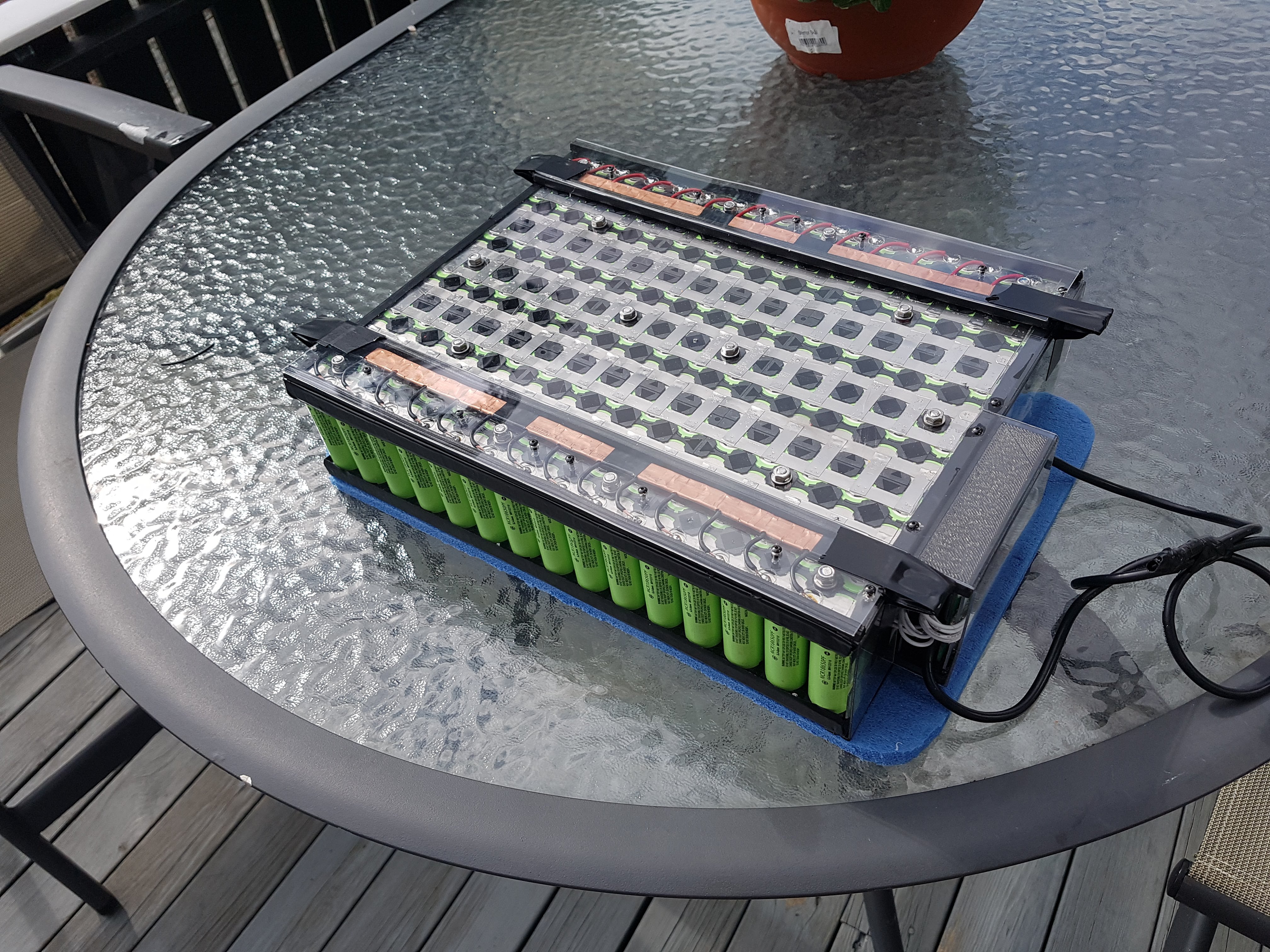
New battery pack coming together, with help from Gylling Teknikk AS. 12s15p Only charge BMS. This should give us 60min ± ride time! 
11 Likes
Will you mount cell level fuses? I have tried various fuse designs, for example with tinned copper wire. I still can not reliably spot weld the fuses to the cells. Spot welding is so much quicker for the nickel connections, but really hard for fusewire.
We will only have a main fuse, on 150 ± Amps. Nickle strips spot welded to the batteries. Needless to say, this will be a battery that you need to know how to use, not entierly plug and play (yet)
What type/brand of BMS and charger will you use?
I got my samsung 25R batteries and will build a 16S12P pack. I’m also building a spotwelder so it’s a DIY on all levels ![]()
I will try to use a 13 A fusewire for each battery but thinking if it could be easier to spotweld a small nickelpiece to the battery and then solder the fuse wire to that. And hope that this will cause less heat to the battery instead of solder the fuse wire directly on the battery.
Here is guy that testing a spotwelded fuse wire: https://youtu.be/H_b3OJuQpEE
Hey @Hiorth Great Work on your project!! Would it be possible for you to upload the solidworks models for your remote design? I would like to be able to make some adjustments to the model if I could, and the sizing dimensions would also prove useful for me as well as others on this forum.
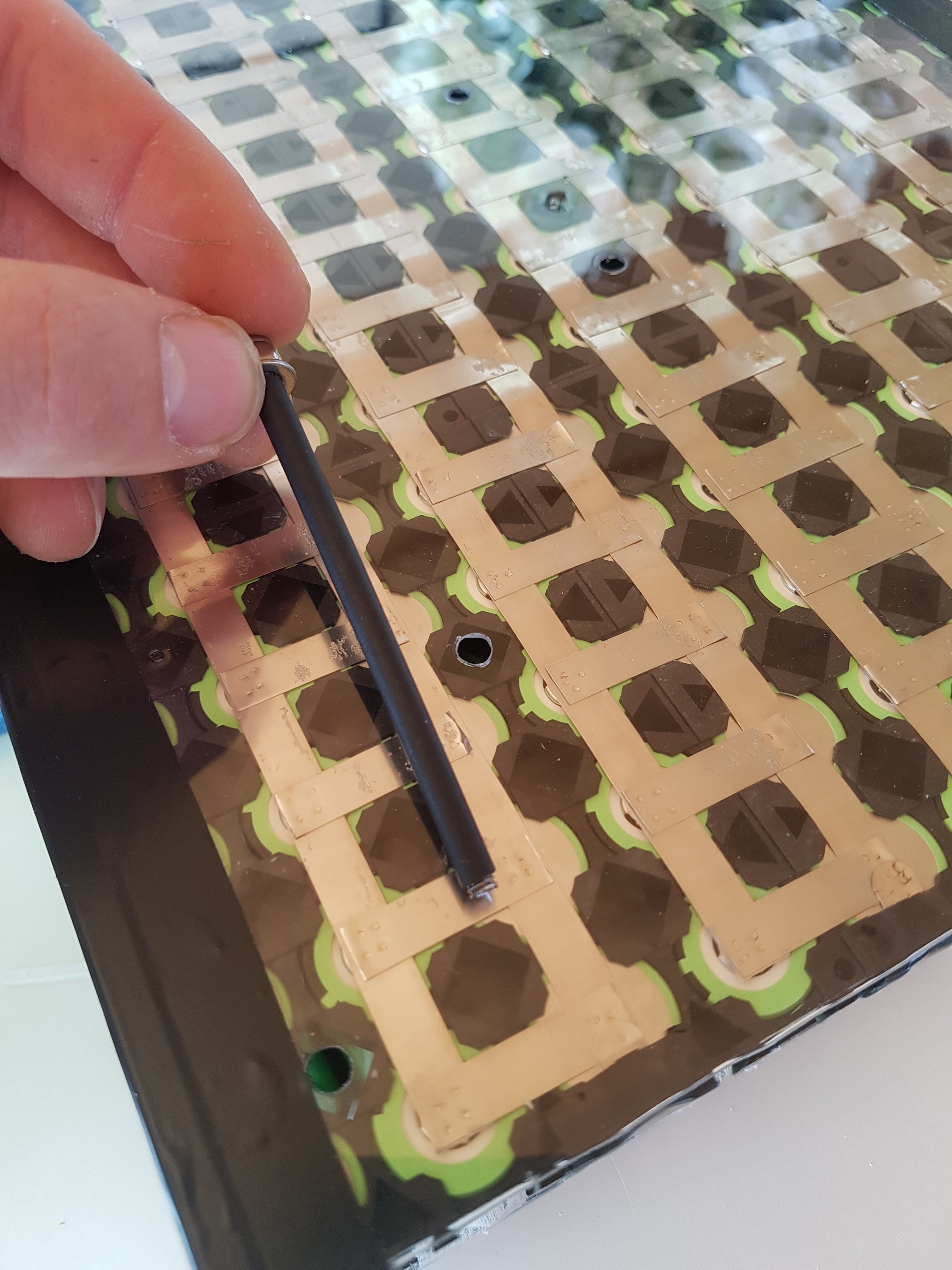
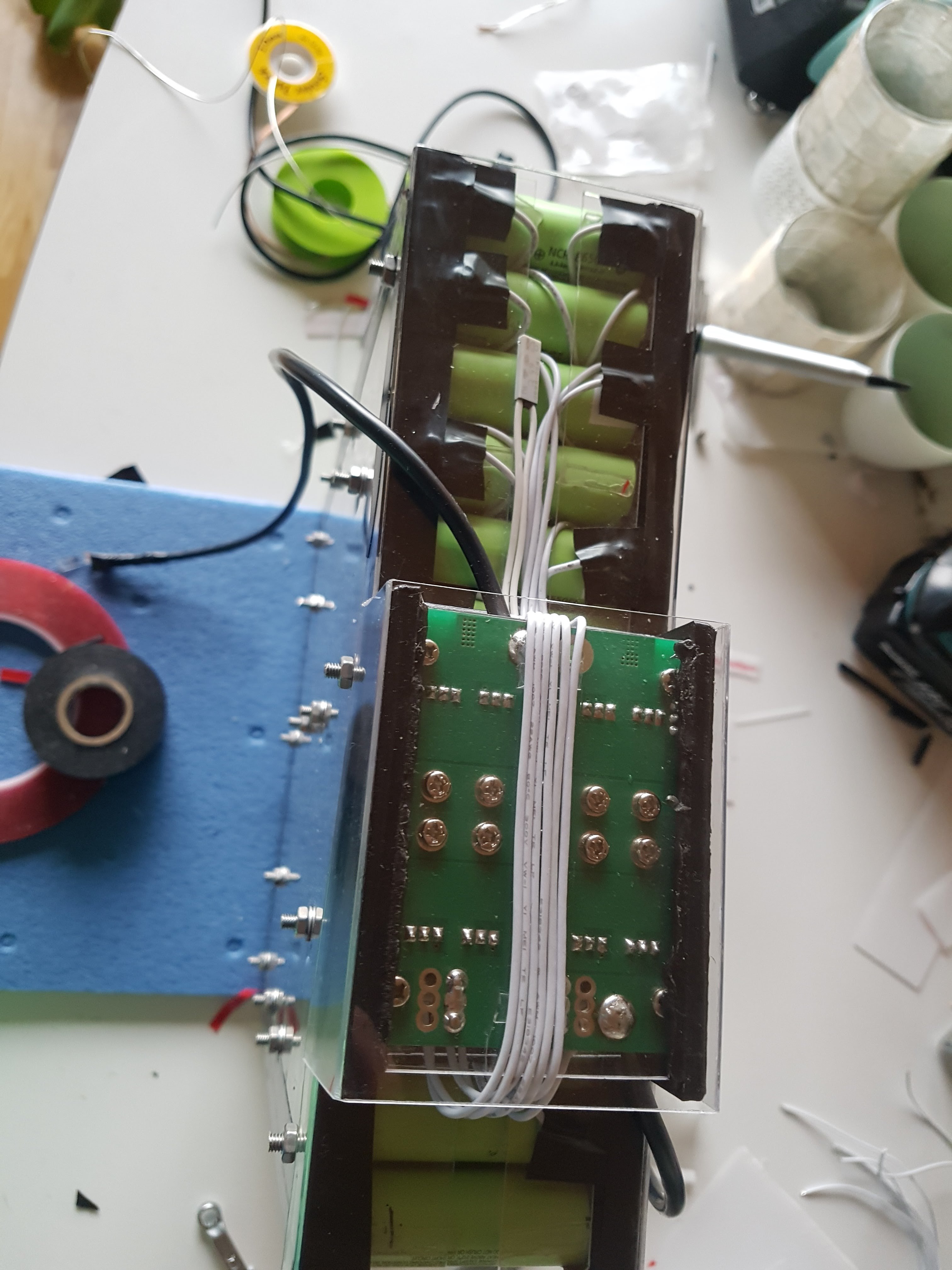
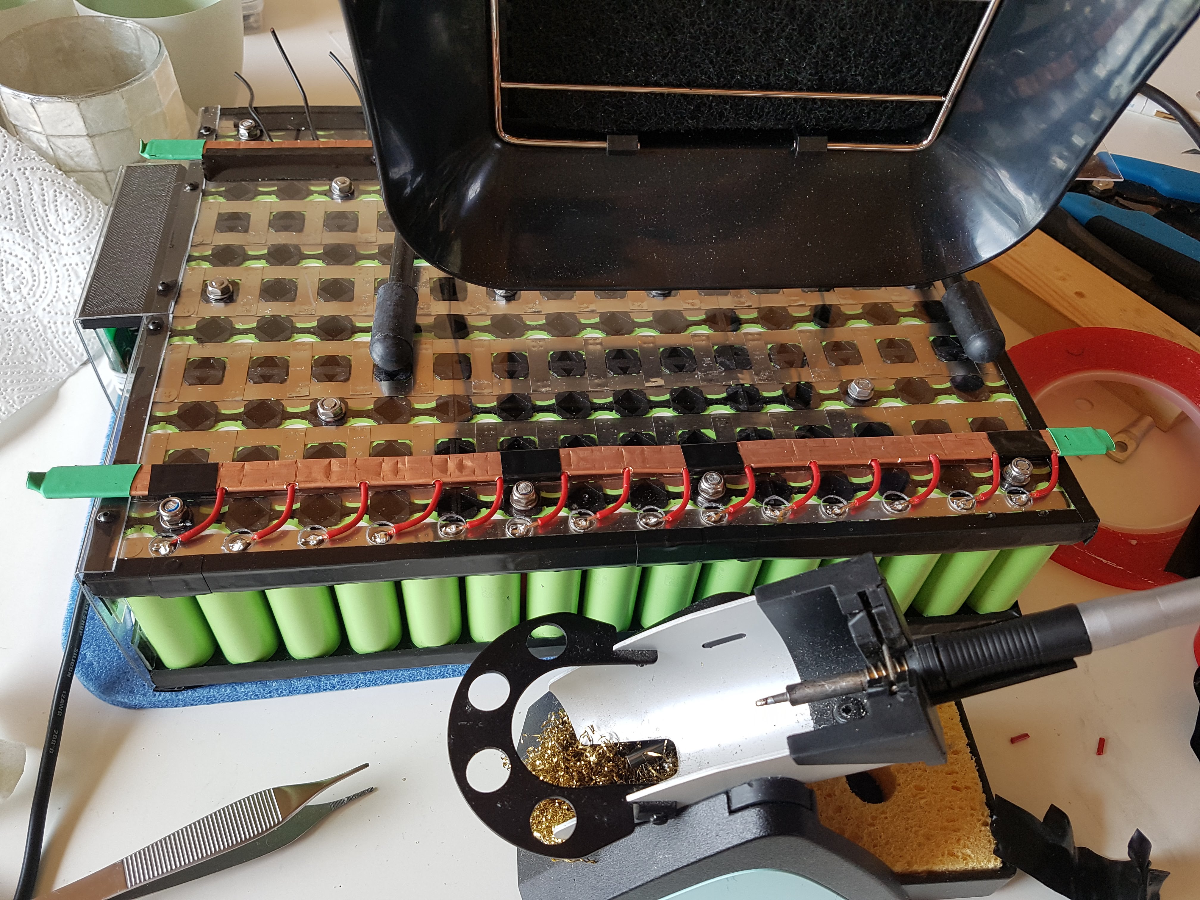
We started working on our 2kwh 12s 15p Battery pack, and its starting to take shape. It will only have a charge BMS, no output BMS (like cordless drills).
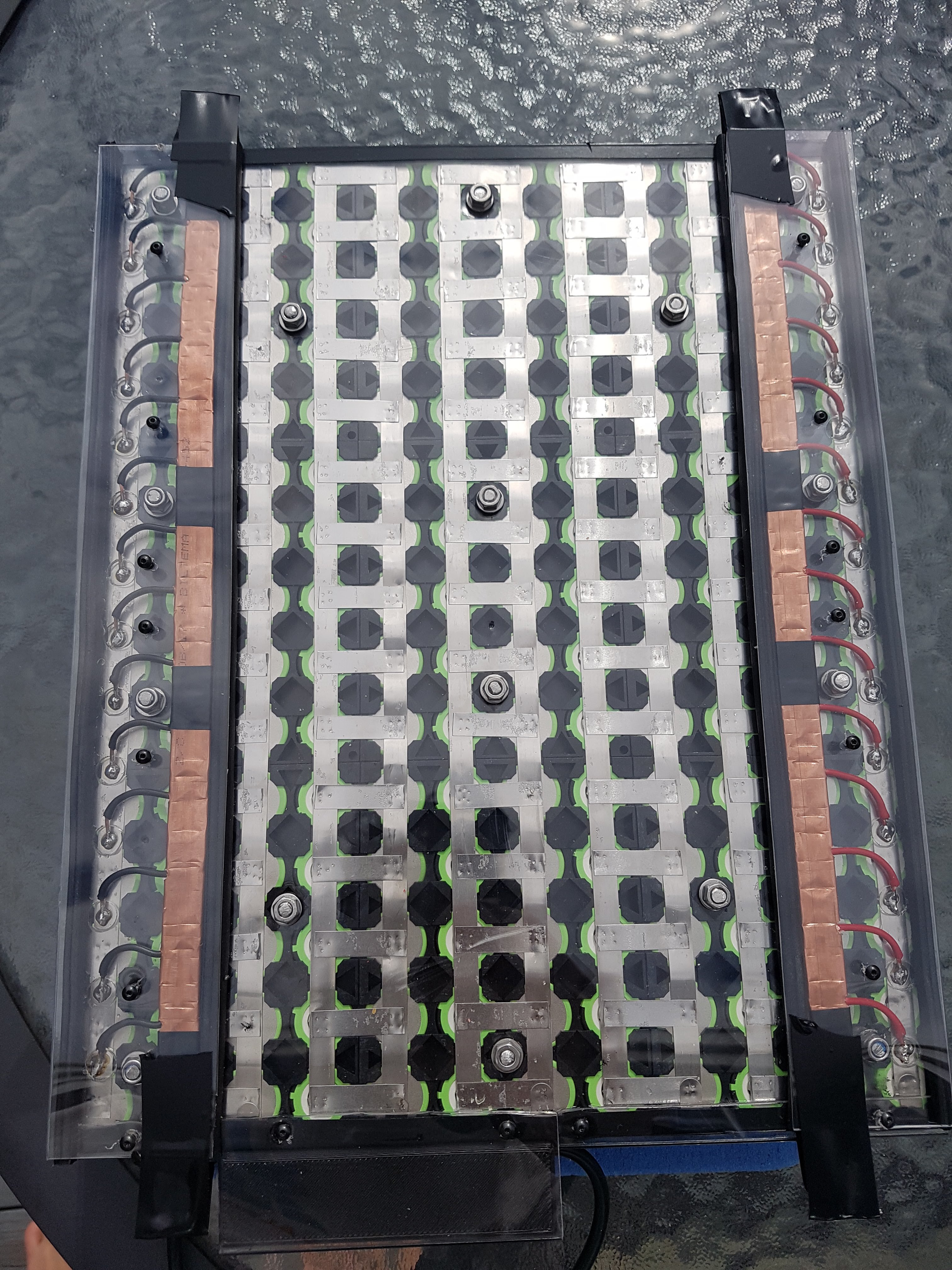
Attached 1mm polycarbonate on each side of the cells, and attached a charge BMS to one of the sides. A custom Busbar made from a squeezed copper tube and 14x copper wires transfers the current to each side of the battery, power out will be on one side while charging on the other.
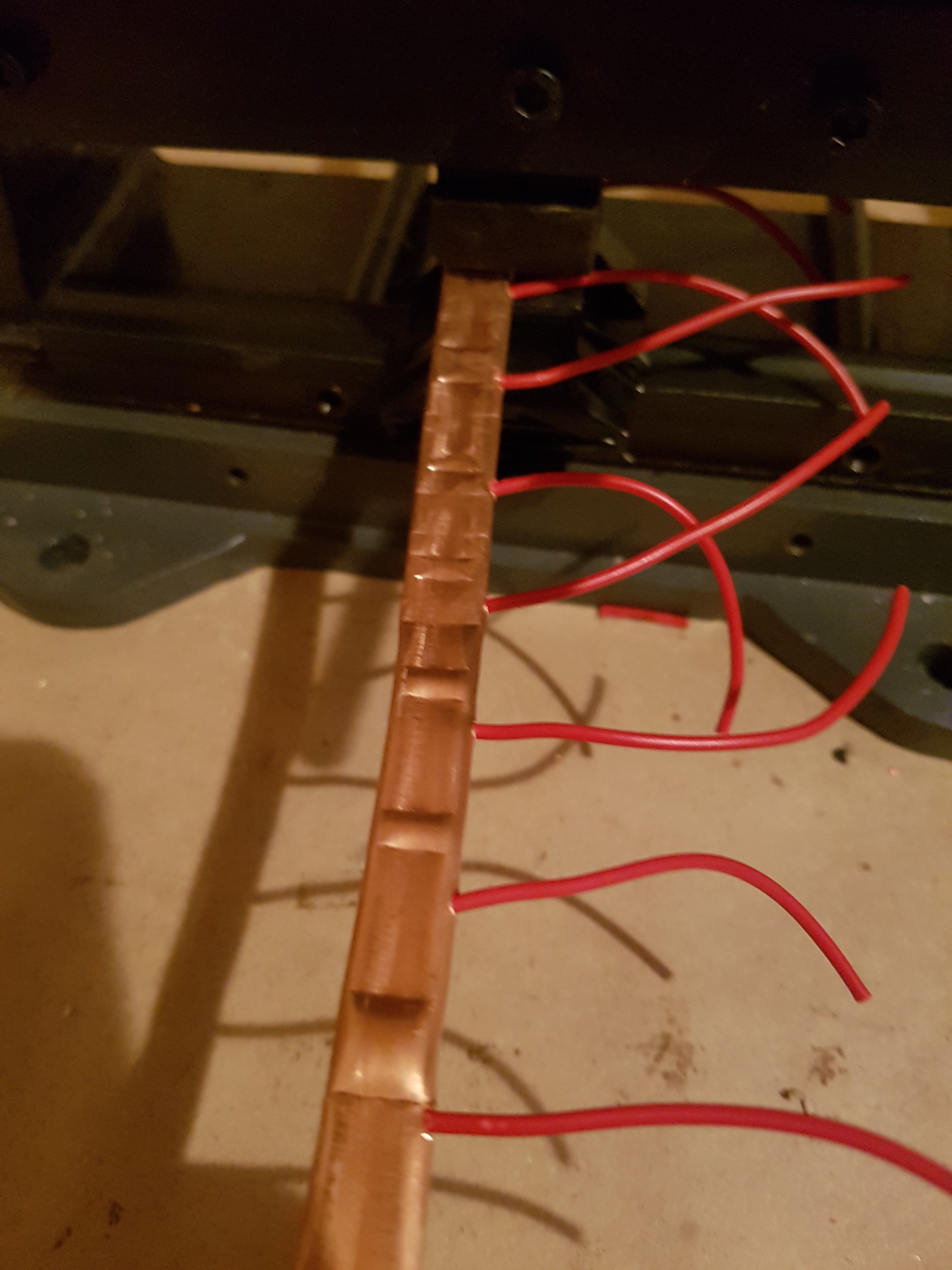
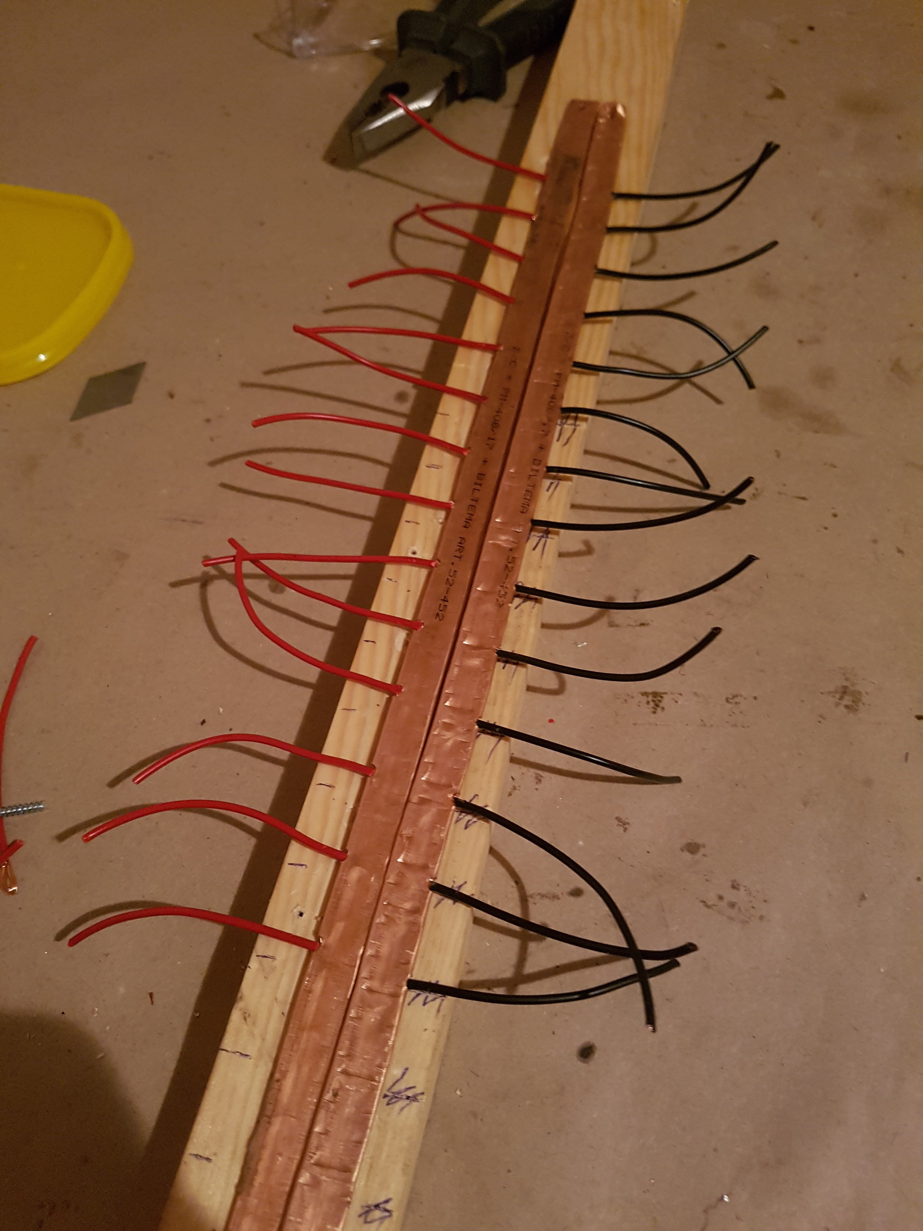
Busbar production: Apx 2cm of the wire was stripped, twisted and looped(bent double) before placed through a small hole in a copper pipe. A press break with a flat tool was used to squeeze the tube flat, did some testing on the connection, it seems to be solid.
Wires from the busbar was soldered onto the nickle between the cells on the + and - terminal, soldering was done with high heat and minimal time, to prevent excessive heat on the cells.
This is the first pack we have ever built, so please let us know if there is something that does not make sense.


11 Likes
Looks great. I never build a battery either. Here is a question, you probably did a lot of research beforehand. I saw that Tesla solders individual tiny wires between each cell and the rail. Those wires act as a fuse. How come you didn’t go that route?