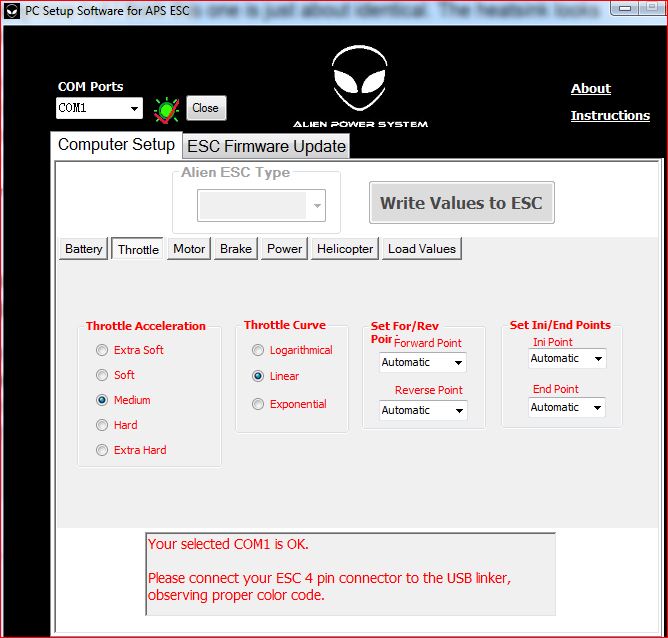
I cant find the link to exact esc im using anymore but I think this one is just about identical. The heatsink looks different (mine doesnt have a heatsink at all, I had to add a watercooling block).
I think the max power issue is due to the motor itself. Its only rated for 1800W and 8s. I was running it off 12s and only getting just over 2000W. If you think of ohm’s law V=IR, so I = V/R. Since the resistance of the motor windings is fixed and the max voltage from the batteries is limited, this means that the amount of current I can push through the motor is also limited. It seems obvious now and I am pretty disappointed in my engineering skills seeing as that I am just now realizing this.
Prop spinning in air pulls around 80W.
I dont have an RPM measurement or esc temp but I did just get an eagle tree data logger with RPM and remote temp sensor so I will be able to get that data next time I run.
Your custom powerglider motor is on the way. Much thanks for working with alien to get this motor made. I ordered it with the shaft coming out of the motor on the opposite side as the wires so that i dont need to run the wires around the outside of the motor to the front of the pod. I did the same with the 5065. When it arrives, I will post the data and results I find running it in oil. I will probably start out with a smaller prop and hopefully work my way all the way up to the solas prop if it doesnt pull too much current.
This is right, but for the 5065 your resistance is about 0,03Ohm, so it should be pulling up to 1500A while blocked.
So at least while blocked you should be able to kill the motor.
Does anyone know how to figure out the number of poles a motor has? Doesnt say on the alien website but I need to know in order to setup the elogger rpm sensor.
I have tried a bunch of different settings in the ESC. I also have the reverse turned completely off so it must be getting a forward signal.
@Giga I just measured the resistance of all three winding circuits and each one is 0.9ohms. If I do the math using Ohms law then p=IV i get about 2,150W at 44v which is right about where the motor is maxing out at. This would explain it right. You can push more current through a resistor (motor winding) than what ohms law says. Agree?
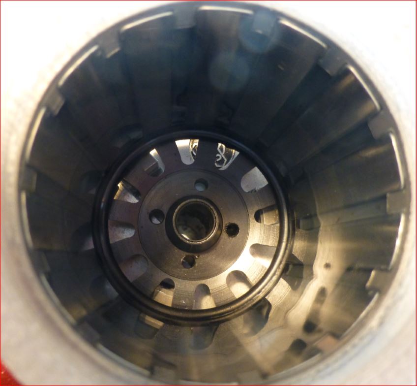
Most of the outrunners utilize 14 magnets and 12 slots. So the mechanical RPM / eRPM is 7.
Your measurement of resistance is surely wrong, but quite normal if you use a normal multimeter. You need to do a so called Kelvin measurement with 4 leads. 2 of them solely for the DC-current and 2 of them to measure the voltage drop. Use some laboratory power supply which can supply some amps at very low voltage.
I emailed Bruno and he said your motor has 12 poles.
I did use a very normal multimeter with a lead attached to each motor lead. repeated the process across all three possible pairs. I may be able to do this test using the equipment at work. Thanks
I guess it is just the mapping of the input. Most likely your signal is a PPM signal with 1-2ms pulswidth, so full throttle always means max dutycycle, the question is what min. throttle means: either max rpm reverse or just still stand/break.
So the real problem is: If your controller expects 2ms puls for max throttle/dutycycle, but your 2$ china remote doesn’t have a precise clock and outputs maximum 1,8ms puls. Then your motor will never see full throttle. I guess there is some initialization procedure for the “Set ini/End Points” where your controller wants to see the whole range of your remote to compensate the wrong pulsesizes.
maybe dynamic in a motor, but not static (stillstand). And I am pretty sure the resistance is not your limiting factor, otherwise your motor turns 2000W into heat and 0% efficiency (which is comparable to a water boiler)
Well if you counted 14 magnets, either of you is wrong. Each magnet is a pole, but you normally set the polepairs (because 1 ERPM is one time N and then S, so comparable with a rotation of a 2pole motor).