so it is possible to use a big 63mm outrunner to efoil?
That’s really interesting, thanks Jezza !
So Alien Power went for no cooling at all and an axial dynamic seal (which is why it needs a spring …).
I’ve got 2 6384 motors and I can confirm that the stator gets super hot really easily if no cooling is installed.
Now I’m going for oil cooling, which, in my opinion, is better than having a gearbox + coupling + extra bearing in term of price and friction.
1 Like
Yeah I think it is possible, just need to perfect the design. I think the best solution would be to epoxy the inside magnets so that they provide no resistance when spinning, and then run the motor in oil.
I have tried to take my 6384 apart, but I cant get the shaft grubscrew off. I think I may need to apply some heat to break the loctite seal.
Yeah using an axial dynamic seal is just a bad idea! Much better to use a double-lipped shaft seal.
I need to get my 6384 apart and get a better shaft on it. I am slightly worried at the thinned wires on the motor though!
Yes, Alien glued it. You can buy it disasembled though, everything comes separated, pretty handy for a DIY assembly.
I think the wires are 12 AWG, it’s a bit too small (only 60 amps max) but I don’t know the max current going through each of the 3 phases…
I don’t think dynamic seals are bad at all. As far as I know, they are the best thing you can get performance and life expectancy wise. But I am keen to hear why you think different.
1 Like
I prefer dynamic seals if the shaft is not rotating. If the shaft is rotating, I prefer a double lipped seal.
Reason being that I have had less leaks with them.
Im using lip seals, not because they are better, but because they are cheap and easy to replace regularly. Mechanical seals are great if you are careful with installation and they are running in clean water. For my application, I wont trust them in salt water. There is not much I do trust in salt water.
Here’s a cheeky video of some testing… Unfortunately the batteries were screaming at me so I did not want to give it too much gas. I would say this is less that half throttle.
I apologise that the video keeps disappearing, the URL signature keeps expiring!
7 Likes
Can’t seem to see the video mate
Its back and working again…
3 Likes
Looking good Jezza!!
Looks Awesome Jezza only just came across this thread!
What size is the motor, 6384? you could try filling it with automatic transmission fluid, it is very thin, I used it on my e-bike hub motor to dissipate heat and it worked well. But still I think the motor may be to small to be efficient at running over 1kw continuously.
Also I think someone else on the forum had problems with current being induced in their out runner that was inside a metal tube, it induced current in the tube causing the tube to get hot, this doesn’t happen?
Awesome work and great progress keep it up!
The battery delivery arrived today and I just can’t resist posting…
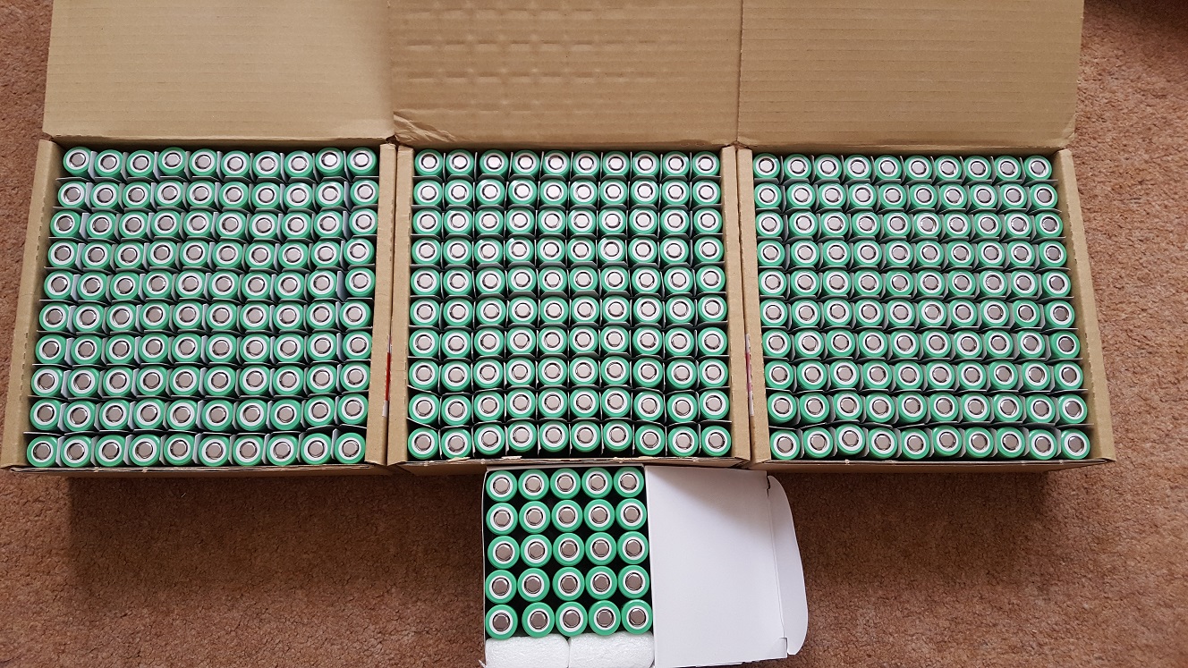
A few Samsung 25R cells

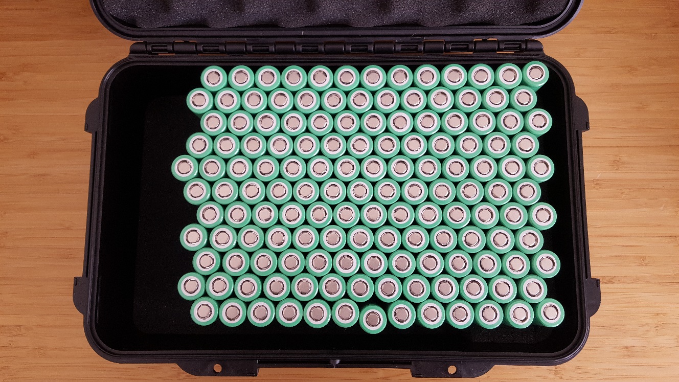
12S12P sitting pretty in their housing-to-be (IP67 which I will turn into IP68)
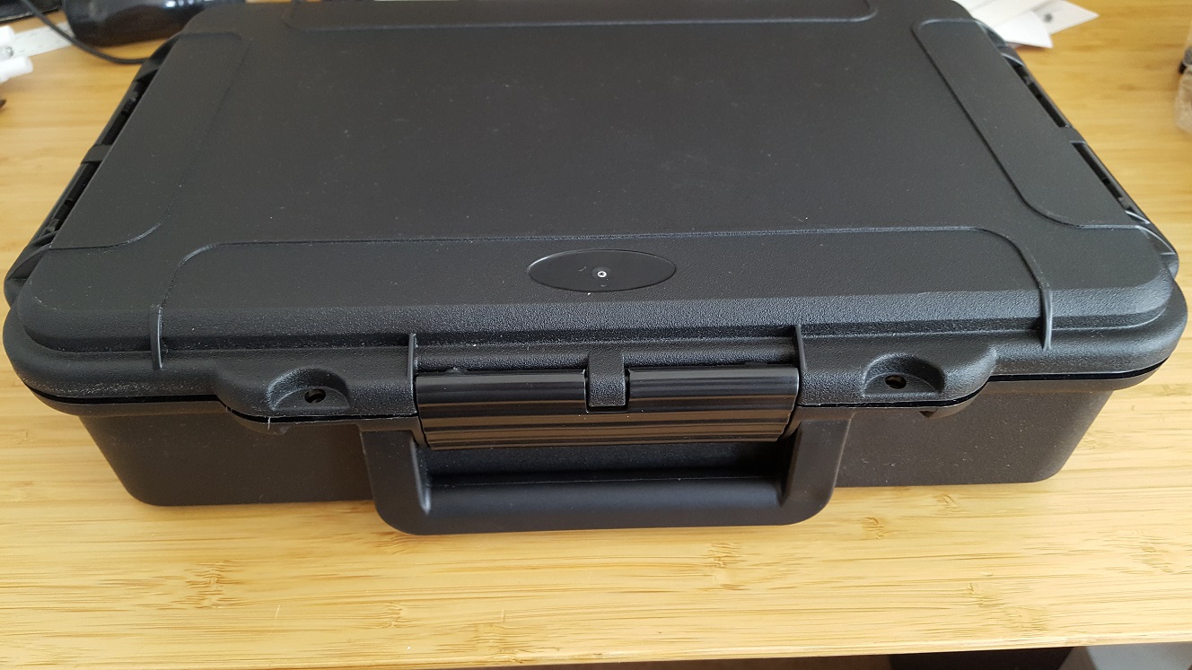
It even has a handy little carry handle. Battery will weigh in at around 7kg with wiring.
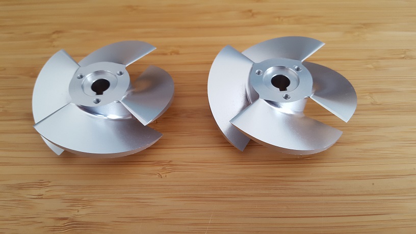
And I also received my jet impellers. I’m a little undecided on how I am going to configure them still. I might try a 6S twin drive to see what happens…but here they are:
7 Likes
Those impellers look amazing!
Now I‘m jealous. i only got one package of weaker cells. I don‘t know about how much you load each single cell, but my pack with 120 cells gets up to ~35 to 40 *C when I pull 5 kW for a while. I planed with a little mor air gap for cooling, about 8 mm in the closest spot. Make sure to get a fuse for the pack, I have already replaced one of those 
Nice impellers, show us the jet soon!
What cells are you using? 8mm is the air gap between each cell?
I used Samsung INR18650-13L 1220mAh - 15A. These cells are only guaranteed to have a internal resistance of <= 30m Ω. The cells are in a grid pattern in my pack and I just checked the distance again, it is 4mm. I traded compactness for safety, as I wanted to use this design for other purposes, too. This way an additional cooling system would be easy to add. I calculated my internal losses with the resistance for the cells and the max current I envisioned for the pack. This number is a maximul value in the datasheet, so I did get away without any forced cooling so far. I fused the pack for only 100A to be on the safe side.
For your cells I found the datasheet (INR18650 25R5) and some test info from a german site[1]. I assume you have 325 cells, which would make a nice 12S27P pack with one cell to spare for a failed spot weld :-). Anway as a quick estimation 5kW/324cells=~15,4W/cell and with a nominal voltage of 3.6V that’s only 4,3A per Cell. Thus each cell even with the guaranteed max internal resistance of 30mΩ looses only 0,55W. With average numbers of 20mΩ its only 120W of losses at max power for the whole pack.
It’s sometimes a hunt to get the datasheet (and revision) which has the data column we are searching for, that’s why I left big margins in my pack design. I figured that I would have enough volume in my board anyway when I get around to glassing the pack in.
Just found this , interesting : safety level … 41c for 5a discharge
I definitely won’t be running all the cells at once as that would add a huge amount of extra weight! I was going to start with a 12S12P pack (obviously fused) and see how that went. The cells should be able to handle it fine, but it will be interesting to see how they are affected by heat. Although the datasheet seems to indicate that at a 10A discharge rate the cells seem to be happy. Once up on the foil I should be cruising with using around 5A per cell so that will be even better for a longer cell life.
1 Like