One second for a full refresh means 10/th second for a 1/10th of the surface. If we create a hierarchy in the parameters and areas/strips on the screen with high, middle and slow rate refresh, a screen with 1 second refresh might do the job.
I am moving to sunlight visible display. I checked couple of available data sheets for these LCD’s and it seems they are only 200 to 240cd/m2. The one I use is 400 to 500 cd/m2 but still struggling under direct sunlight. I am moving to sunlight visible display:
available at Digikey and mouser. They have some rough drivers and there is drivers online for the similar lcd driver chips
@samisin The Newhaven displays looks rely interesting. I will do a quick search to see if there are any libraries available for my teensy
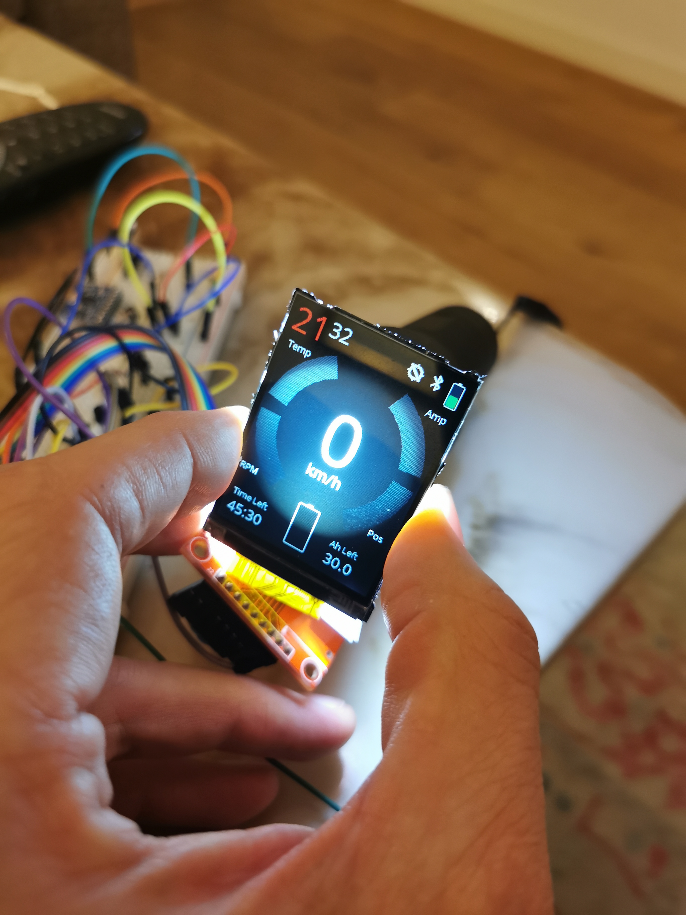
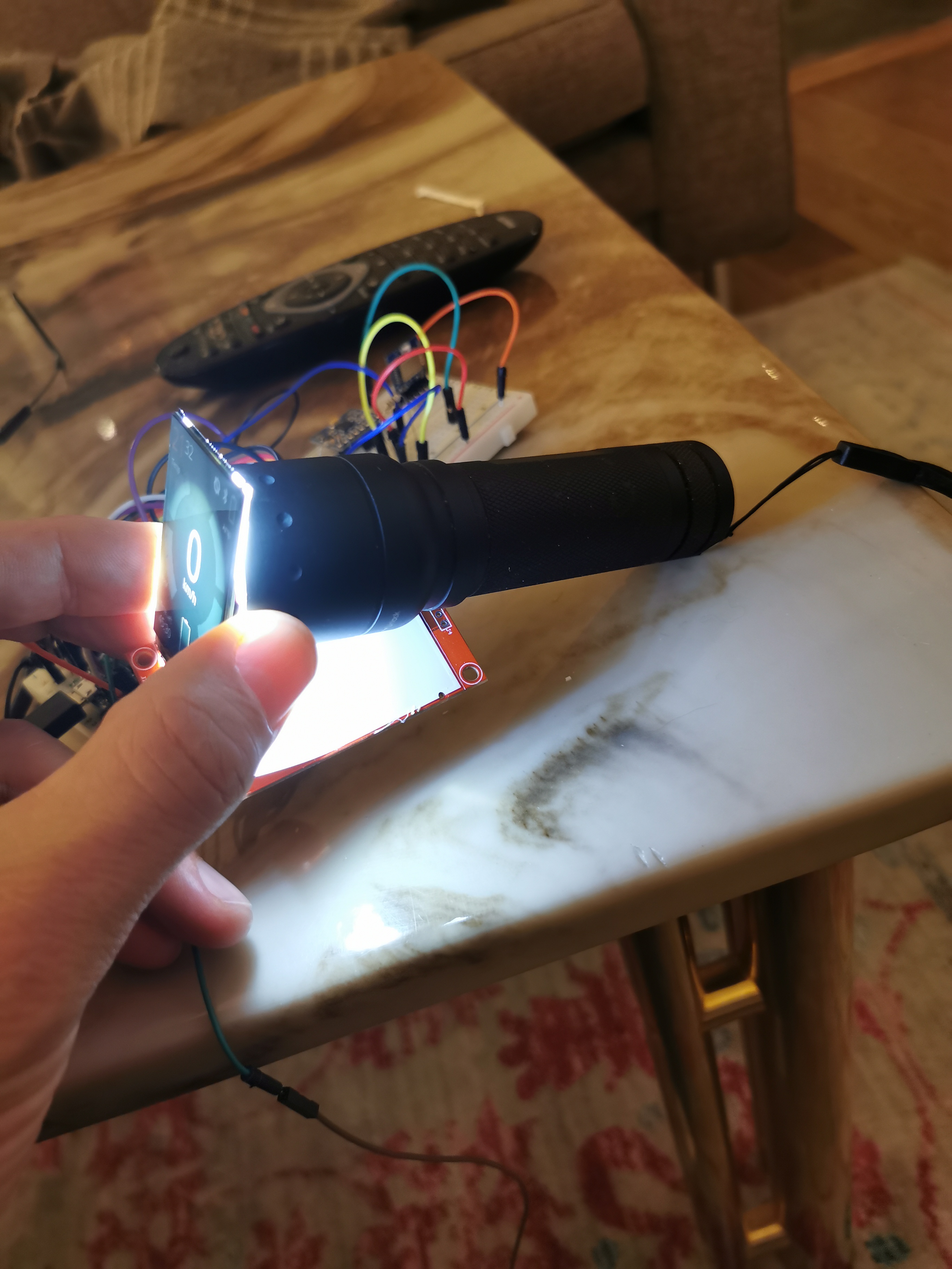
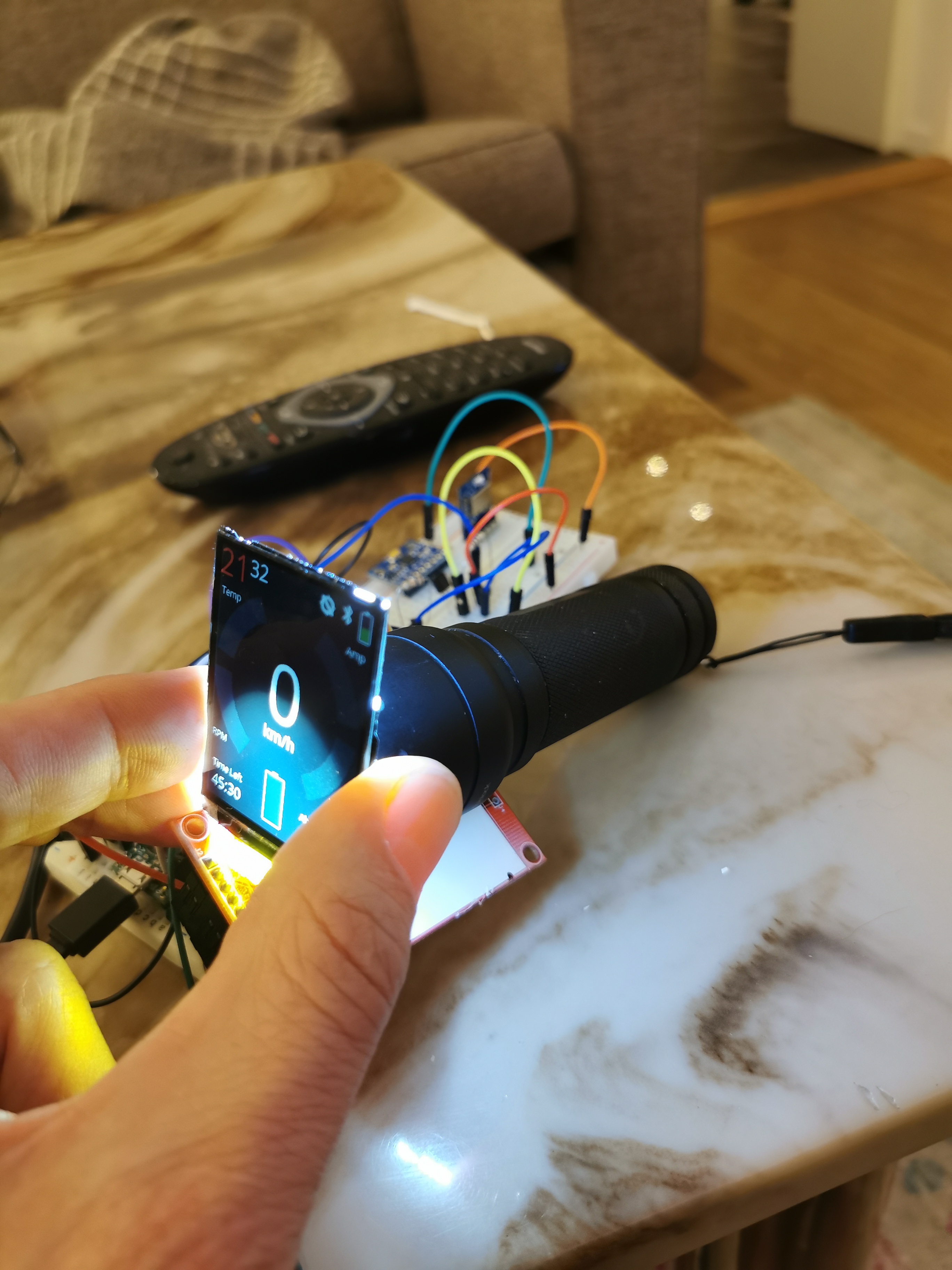
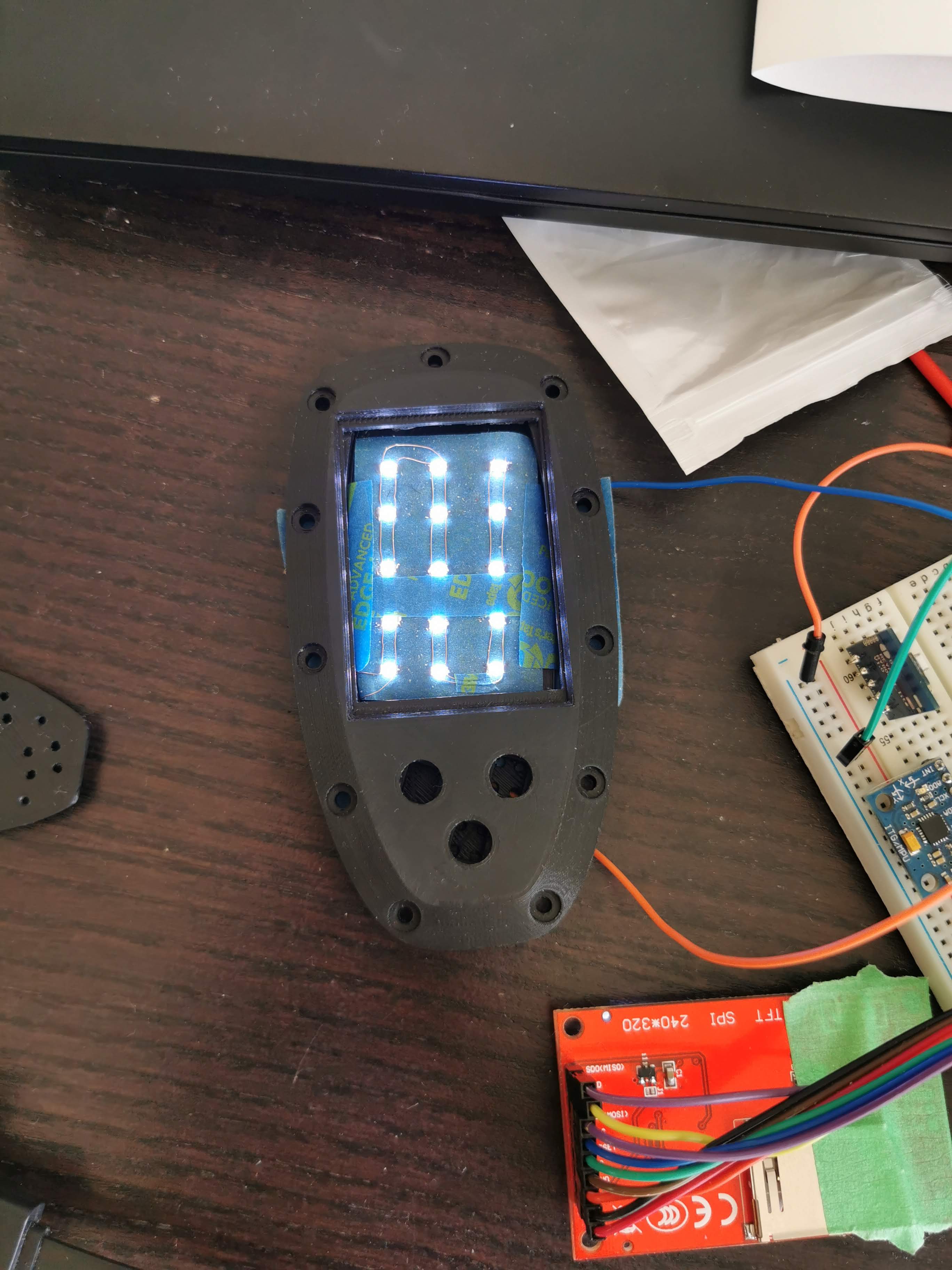
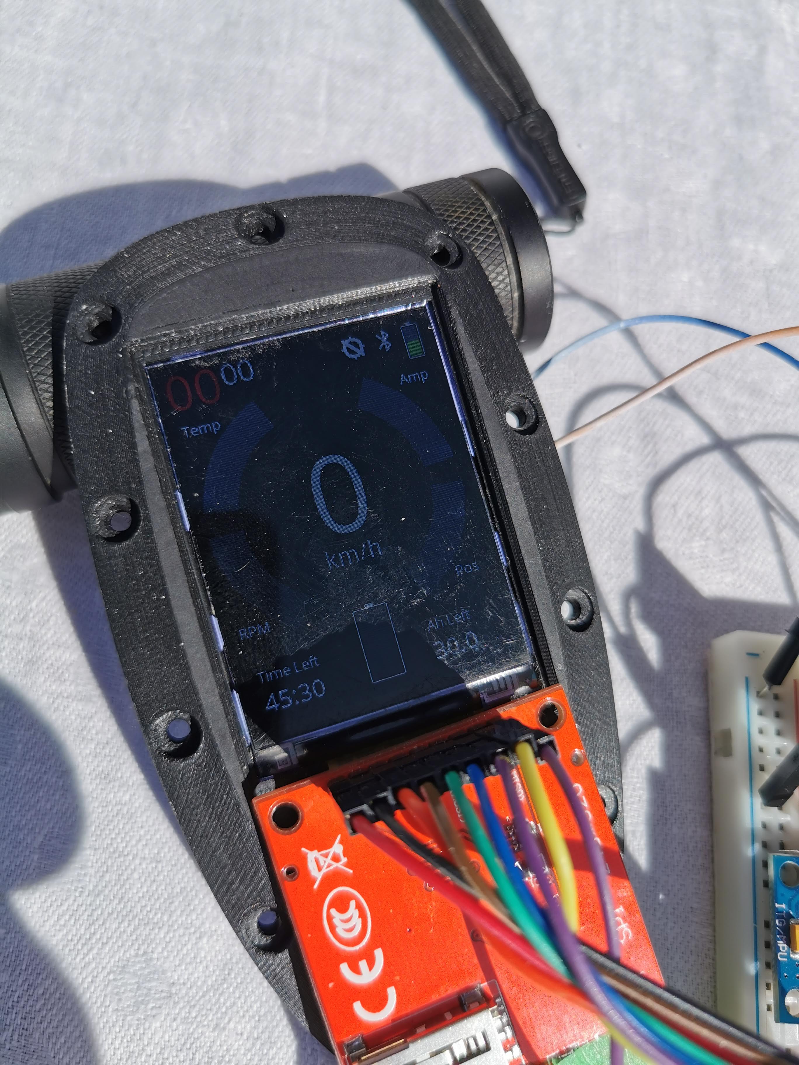
I might have a solution to my visibility problem. I tested t.o put my old flashlight behind the screen and what a difference! The images below doesn’t relay show the brightness. I have 4 or 5 mm between the PCB and the display so a couple of smd 2835 leds or similar will fit without any problem. The forecast is sunny in Oslo tomorrow so I will give an update on the flashlight trick, outside, in the sun
3 Likes
That might work actually. To have smt led matrix in the back with thin defuser sheet between led’s and display and control the dim based on ambient light.Then you turn cheap lcd to day light visible! The draw back is power consumption. But let me give you another good idea! use emu to turn the backlight when user brings the remote up. Plus a single 3000 mah 18650 cell will provide more than 8 hours in worst power consumption scenario
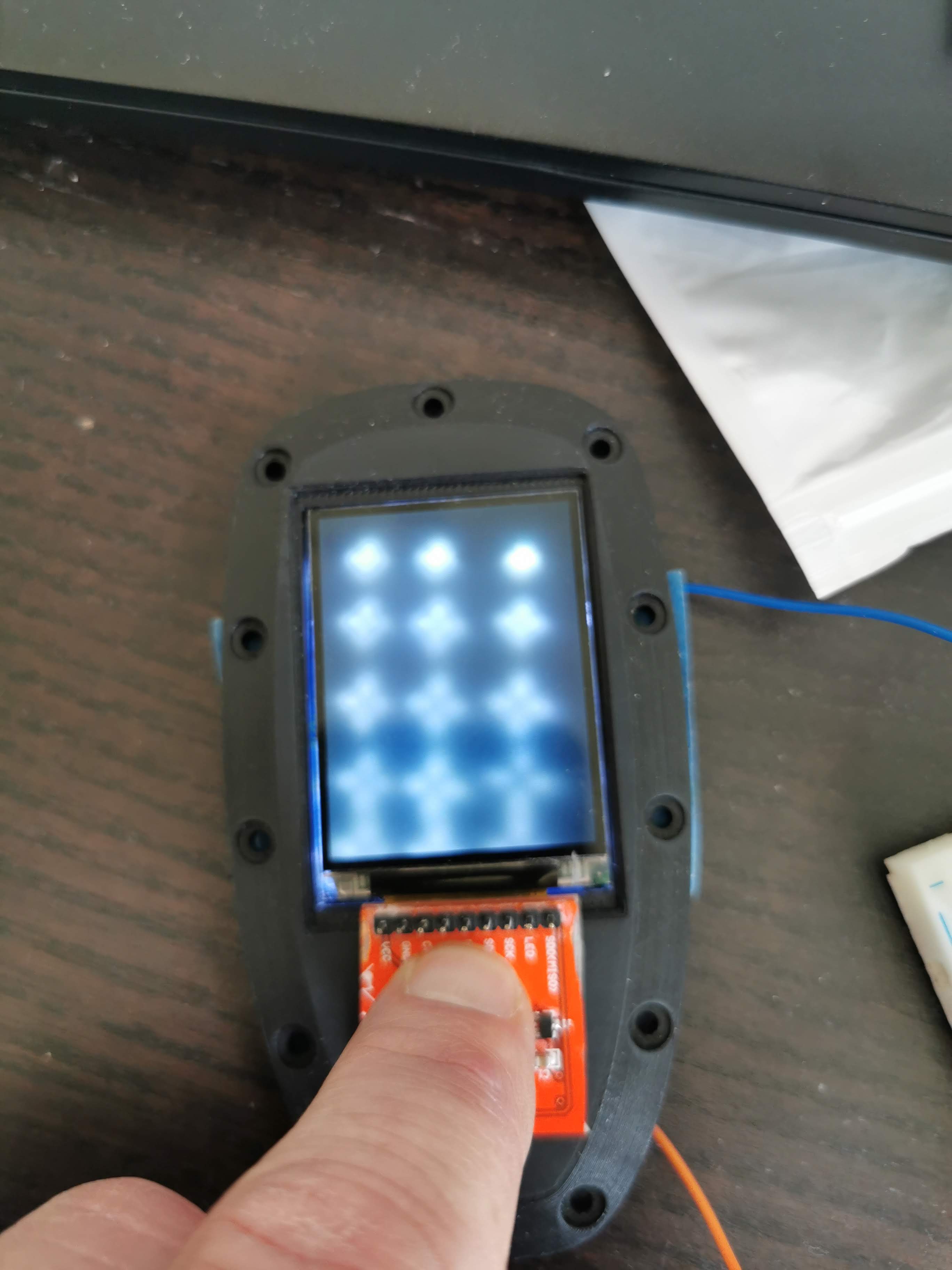
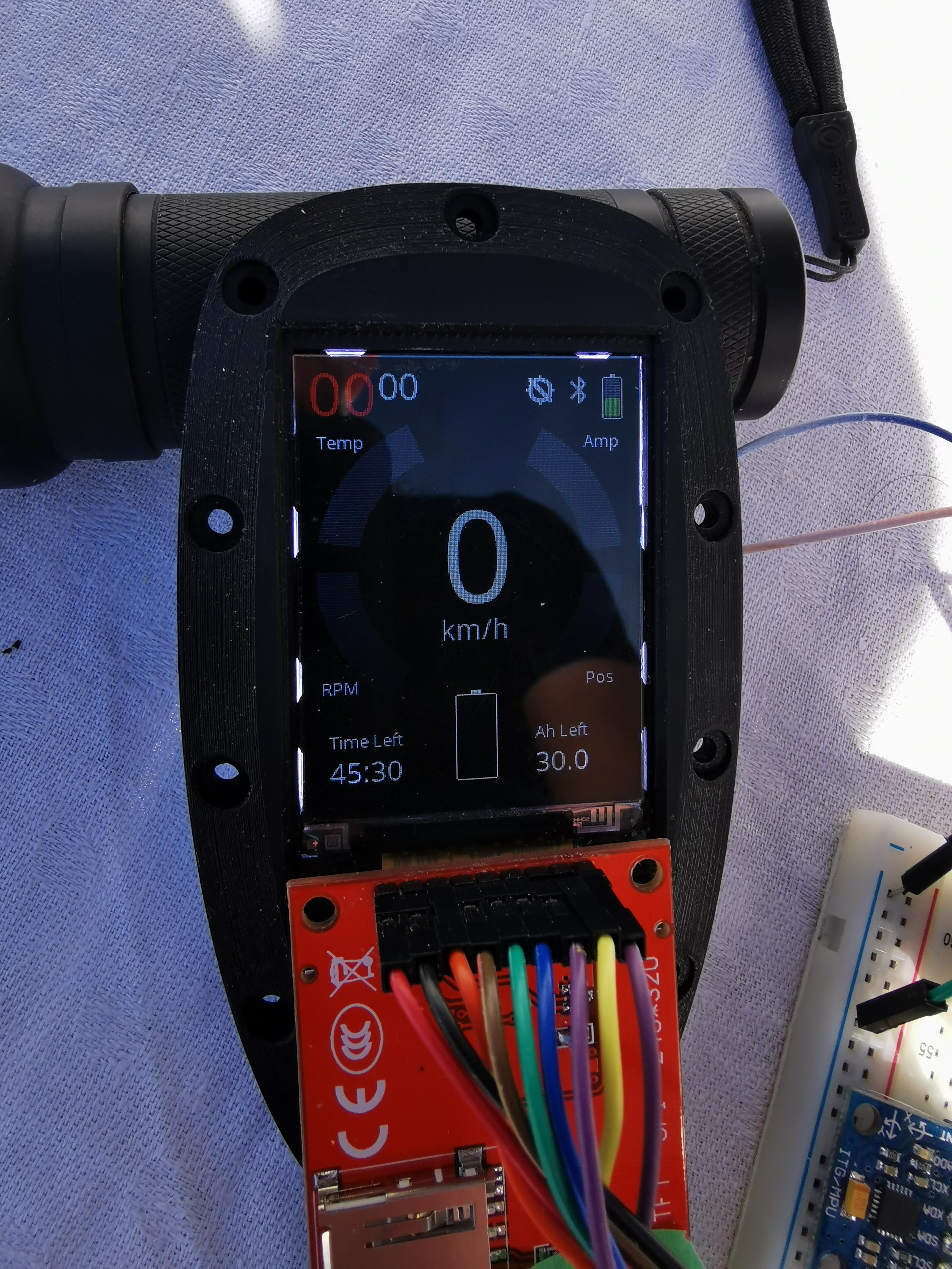
@samisin I think we actually have a winner. Here is the display in direct sunlight and for once, the images reflects the reality, It’s crystal clear. You can clearly see on the middle of the battery indicator where the flash light stops. I’ll do some more experiments in the afternoon and get back.
Yes, you can do a lot of smart things with the IMU, proventing the battery to drain. Shaking the remote, move it to a defined position or …


9 Likes
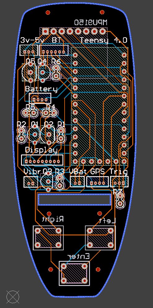
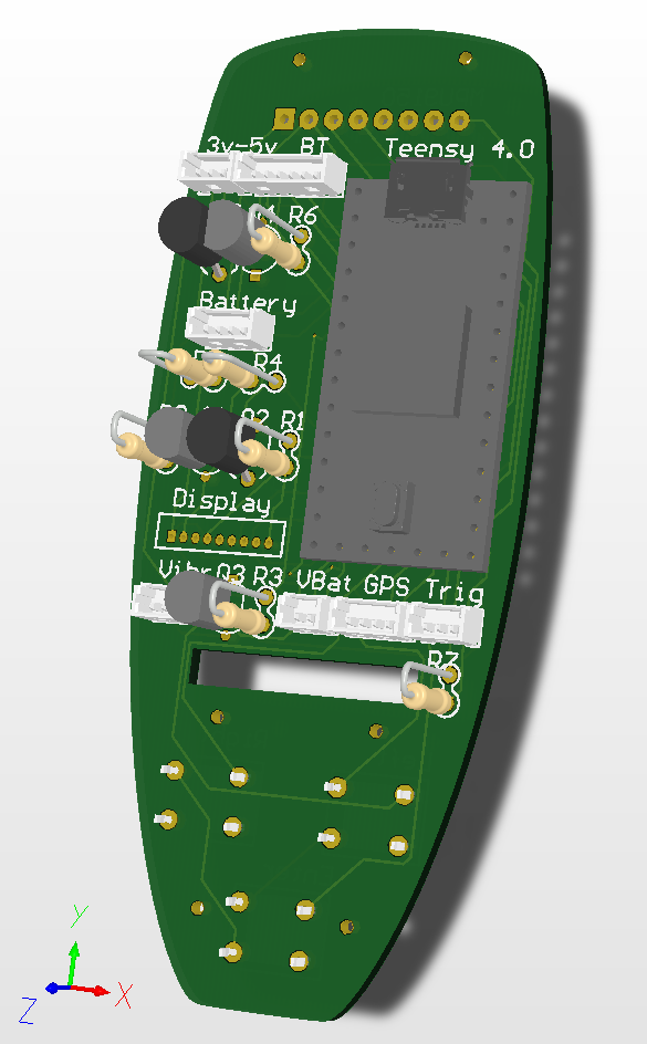
PCB
The Gerber files are sent for manufacturing of the PCB. I have used Seeed Fusion, 10 copies and shipping to Norway with DHL for 25 USD.
The files has been reviewed and accepted by Seeed and as of yesterday in production and expecting the PCB:s by the end next week.
As the PCB has not been tested yet i real life, there might be updates, but hopefully not, and there might also be an update regarding the sunlight visibility once I’ve done a proof of concept.
Since I’m not so happy with the bluetooth module I’ve added an extra connector that will be used as a jumper, being able to use either 3.3v or 5v power supply to the bluetooth module. That will give me a possibility to change the module later
Also, I’ve added a connector for a GPS module making it possible for non VESC users to track the speed.
Electrical schema
Gerber files
CircuitMaker source files
Modules
Teensy 4.0 Teensy® 4.0
ILI9341 2.2 Inch Display https://www.aliexpress.com/item/33012793224.html
HC-05 Bluetooth https://www.aliexpress.com/item/4000587203886.html
Vibration Motor https://www.aliexpress.com/item/32849172232.html
Charger 5V no pin https://www.aliexpress.com/item/32816412117.html
Hall Sensor https://www.aliexpress.com/item/32597268764.html
MPU9150/6050 Gyro/Accelerometer https://www.aliexpress.com/item/2035920870.html
Tactile Switches 6mm or 7mm height https://www.aliexpress.com/item/32857436208.html
Resistors
R1. 100
R2. 2.2k
R3. 2.2k
R4 10k
R5. 3.2k
R6. 2.2k
R7. 6.8k
R8. 2.2k
R9. 2.2k
R10. 2.2k
Transistors
Q1. 2N3904
Q2. 2N3906
Q3. 2N3904
Q4. 2N3904
Q5. 2N3906
Q6. 2N3904
Connectors:
Any 1.25mm pitch through hole connectors will work. I’ve used these ones from AliExpress https://www.aliexpress.com/item/4000134796645.html
2 x 2 pins
1 x 3 pins
2 x 4 pins
2 x 6 pins
1 x 9 pins
Connector output. The names represents the pins on the actual module
Bluetooth:
- Vcc
- Reserved, Not connected
- AT mode (Pin 34 on the HC-05 module)
- Rx
- Tx
- GND
3v3-5v (This one is just a jumper to provide either 3.3v or 5v to the bluetooth module)
- +5v
- When using the HC-05 module, connect this one to the +5v pin.
- Vcc
Display
- Vcc
- GND
- SCK
- Reset
- CS
- DC
- SDI (MISO)
- SDO (MOSI)
- LED
LED
- Vcc
- GND
Trigger
- Signal
- GND
- Vcc
Battery
- +5V
- GND
- Plus side of the battery
- Small led on the charge board indicating charging
Vibration
- Vcc
- GND
GPS
- GND
- Vcc
- Tx
- Rx
VBat
- +3v
- GND
MPU9150
- Vcc
- GND
- SLC
- SDA
- INT
- Not Connected
14 Likes
Hello
It is great your remote control, thank you for all this information, can explain how you do to install the program in the transmitter and in the receiver, thank you
Philippe
Fantastic! Great job!
2 Likes
The Teensy is basically just an Arduino, just a bit more powerful. Programming and uploading programs is done form the Arduino IDE or like me, from Visual Studio with the VisualMicro extension.
Right now the receiver is just a bluetooth module, connected directly to the Flipsky VESC. The next thing will be to finish my receiver, that will extend the functionality with battery information, controlling the water pump, managing GPS data and so on
2 Likes
ok thank you, so if I use a USB module on a VESC no need for a file for the receiver, the file to download on the transmitter is where because I can’t find an “.ino”
Absolutly amazing job!
This is the remote I will use in my project.
Question
In what material are you printing the remote? ABS PLA PET…?
Br
Magnus (Mon72)
Gothenburg
I’m using PLA but I guess you can use both ABS and PET
1 Like
Thanks,
I will start to print the remote components right away tomorrow.
Looking forward to order your circuitboard, build it and test the software against the rest…
It looks awsome!
Br
Magnus
Very nice work, bravo. If I get the circuit boards right, will they be available for purchase? I’d be interested, too, if it’s still possible.
Thank you.
@Manu No, I will not sell mine.The Gerber files I have published, is for everyone to order their own, from the manufacturer of their choice
4 Likes
Update on the sun visibility problem
I found 15 small 1206 smd leds in my drawer. Don’t know the specs, don’t remember where I bought them but any how. In the first attempt I just soldered the leds together in parallel and mounted them behind the LCD.
Big failure! I just saw stars and I don’t think any diffuser can fix that problem.
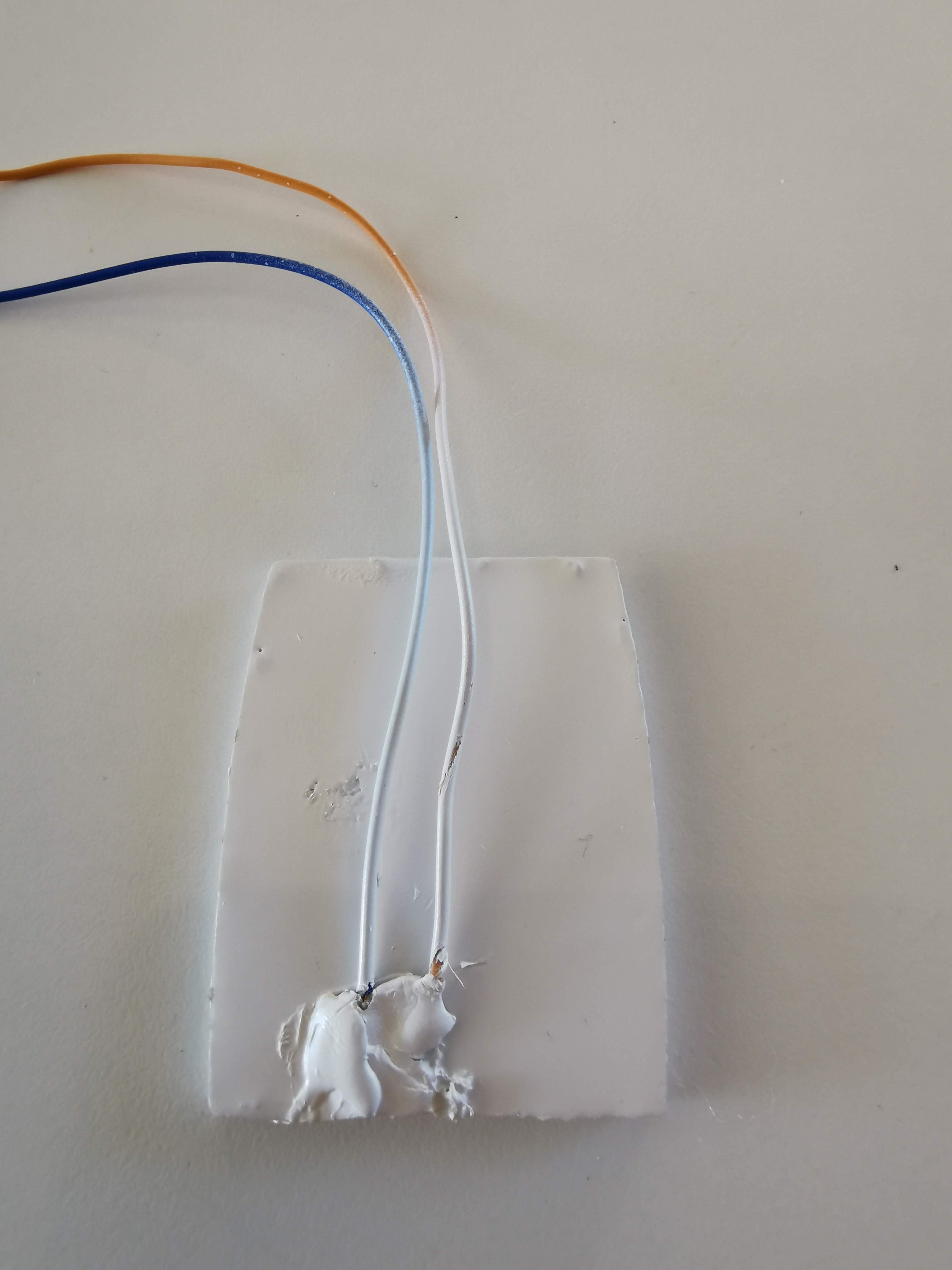
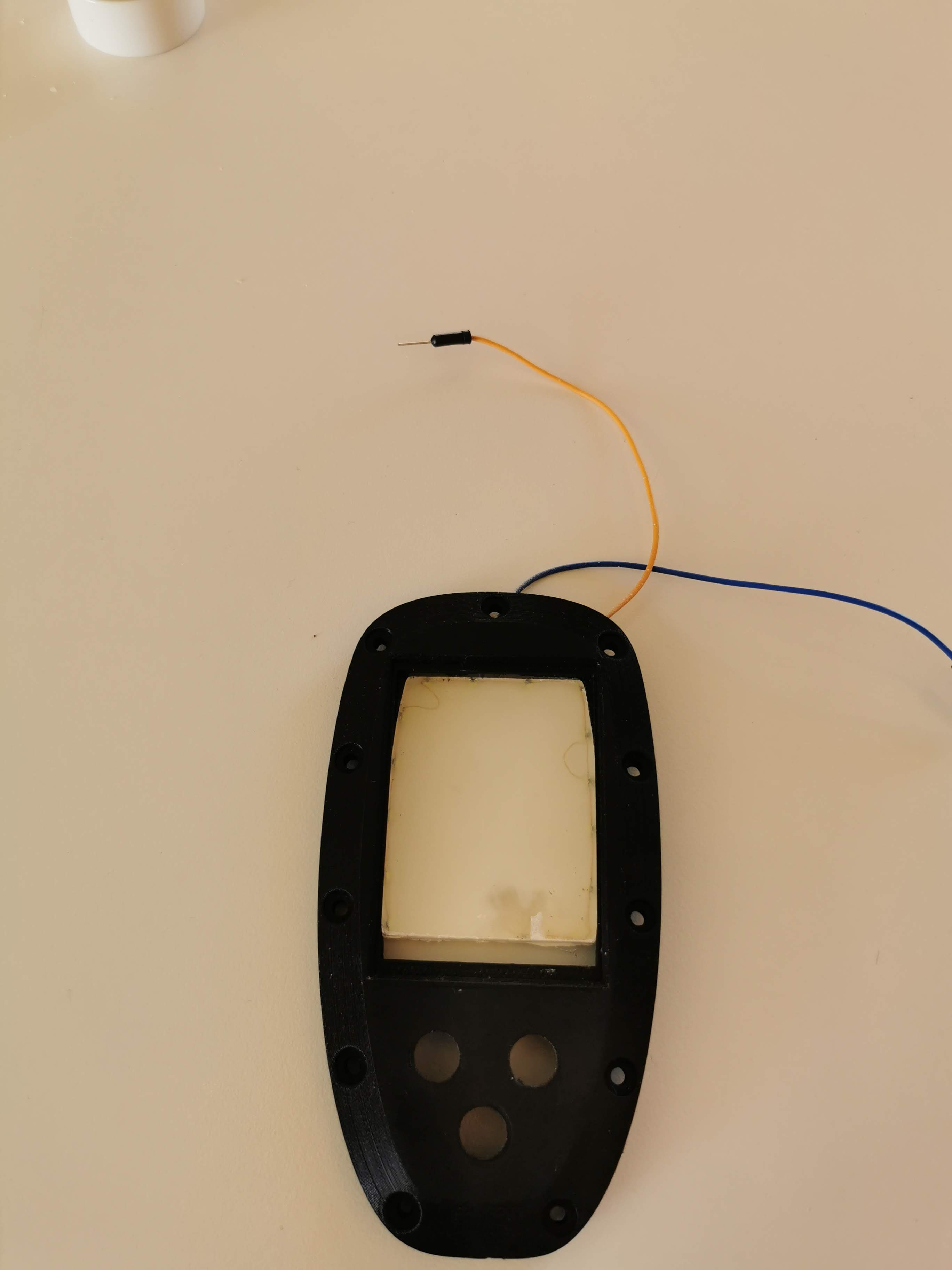
So back to the drawing board. So what if I created a small mould, glued the leds to the side of the wall, filled the mould with clear epoxy resin and spray painted the back and sides for preventing the light to escape. Here is the result.

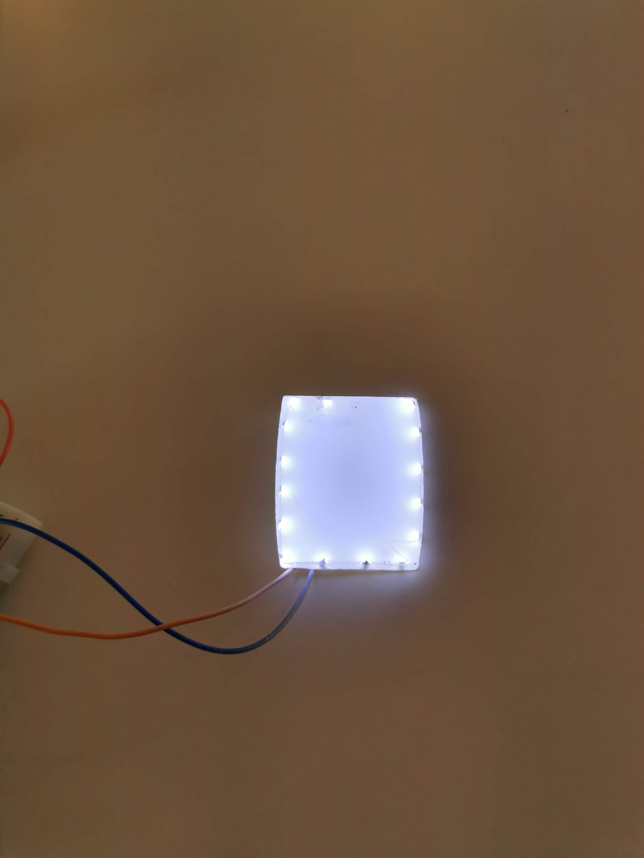
!
It’s not perfect, not as good as putting my torch behind the LCD but I think I’m on to something, considering that all 15 leds only draws 150 mA, that’s 10 mA per led. I’m quite sure I can find leds that draws 20 or 30 mA, have to look that up and order some.
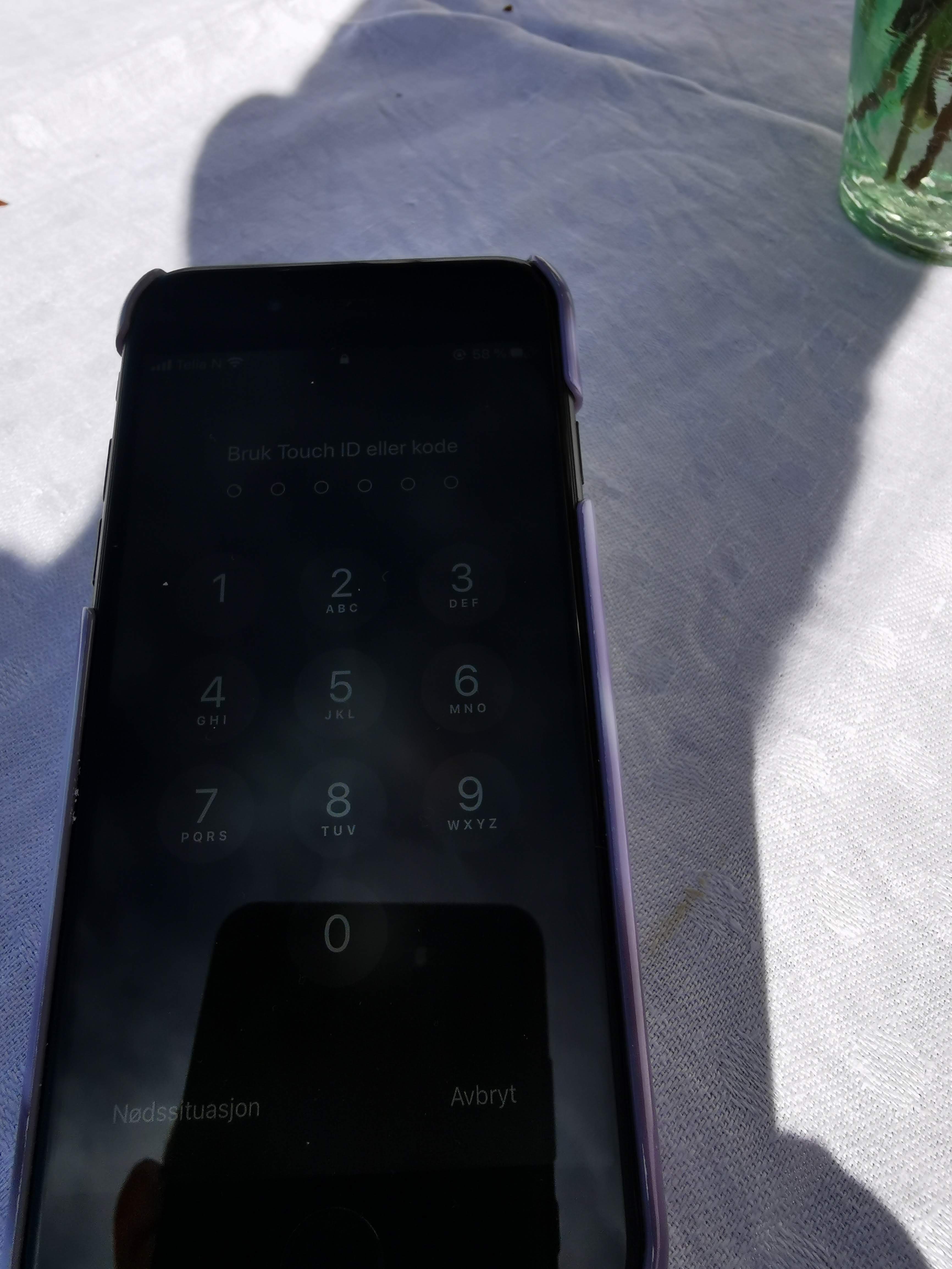
Also, compared to my daughters iPhone 8, I think I have much better readability. No point showing the iPhone in direct sunlight. Didn’t see much.
4 Likes
Hi
Regarding ordering with the gerberfile… would you say that the circuitboard in it’s final version or should we wait a while until you are finished with this amazing remote project.
Br
Magnus
Hej Magnus, alltid trevligt med en landsman på tråden.
Well, I would perhaps wait until I’ve tested the PCB, hopefully later this week If I haven’t had a total barinfart, most of the things can be fixed with small patches. The extra led for sunlight visibility CAN be connected to the existing LED pin on the display, perhaps just changing one PNP transistor (Q2) to a more powerful one. But ultimately I will change the PCB slightly, perhaps a new connector for the extra leds and a new connector for the IMU because it might not fit between the PCB and the display any more.
I will wait untill working circuit board and control. otherwise I will just have to order a new board.
What motor and controler do you use for your foil. Any thoughts about the batterypack yet?
Br
Magnus
I’m using the Flipsky 200A VESC and the FS65161 motor. I will start with the battery pack (13s12p) I used for my Segway a couple of years ago (hopefully it will be enough)
1 Like