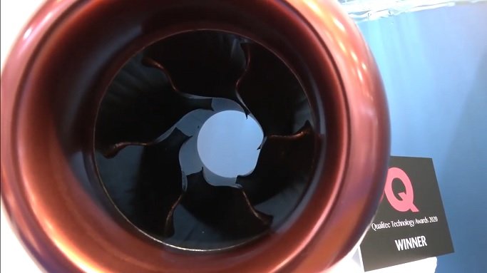
Who here at efoil has attempted science informed experiments with waterjets also known as hydrojets? I found this during a search in the forum.
Most of the leads I found are well-intentioned hobbyist who hadn’t done enough research beforehand. I would like to contribute what I can with experimentation in designs with ducted prop variations, true water-jets, and a new technology I have been watching developed by DeepSpeed (https://www.deepspeed.it/product/?lang=en).
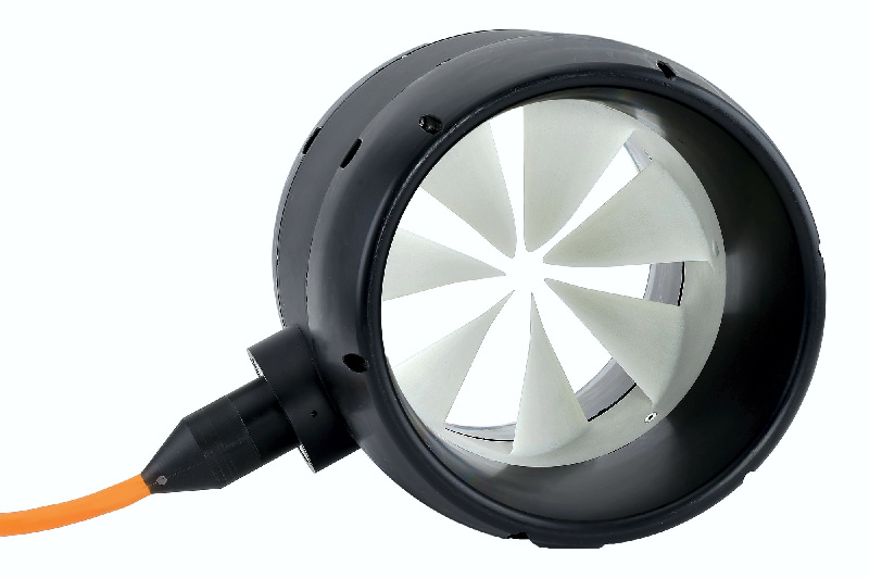
My early ducted impeller was a hubless concept. The prop blades of a rim-driven thruster are mounted on a ring which constitutes the rotor of an electric motor. It is surrounded by the stator which is also ring-shaped and creates the necessary torque. Rotor and stator are water tight and the whole unit operates submerged. My design proved low environmental impact, quiet, safe, but unfortunately too inefficient for use as a primary drive.
The DeepSpeed drive is a hydrojet, instead of being positioned inside the hull as a typical hydrojet, is configured as an outboard that sits under a boat, with two open ends. The theoretical advantage is that the inlet flow of water becomes dynamic – as the water starts flowing through the open-ended jet a dynamic flow is created. In essence the faster the boat goes… the greater the flow… the faster the boat goes… the greater the flow… and with increasing efficiency.
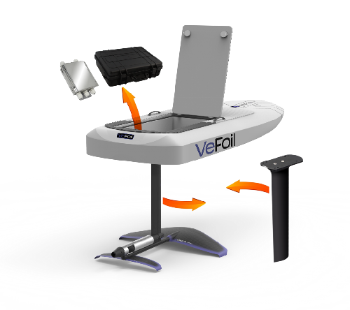
I found this VeConcepts and their VeFoil design.
A typical fixed foil with a hydrojet engine that is described as very efficient. (https://veconcepts.com)
So I have Helical Drive (Screw) Impeller Design that I am currently down scaling to D53 x 325mm long. I have performed Inviscid Flow simulations with good power to thrust results. I would like to see if equivalency exists at the smaller scale (currently D1250 x 10000). Therefore I am looking for some people with 3D printers, that would be interested in printing the Duct/Housing, Rotor/Impeller and “hacking” a motor installation for Thrust Testing. I would post the STL files for the Duct and Rotor if there is sufficient interest. Please note that the actual Design requires that the Motor Stator is fixed to the Duct, so the typical drive configuration is reversed …
If we knew your general location it would have helped in pairing you with a resource able to work closely to generate multiple iterations of your design as you test, reaching your goal more quickly and at lower cost. In specific, I would like to help find a local MakerSpace community for you to collaborate with in reaching your goal.
Here is the definitive MakerSpace Directory you can search. Though “Shelter In-Place” guidelines are being enforced around the world, many Maker communities have online resources that let you upload your design and kick off and printing, and pick up the finished widget later if it completes successfully.
I say this from the perspective of an Engineer, Systems Analyst. Most of my corporate work was being tasked to do Project Management, something I don’t particularly love but am unfortunately very good at. Anyway, doing so reduces systemic costs and helps team members be more effective by when possible to selecting those people and resources from sites in close proximity.
Muiren, I posted my comment because this community should be familiar with general performance of a Propulser … I am not … the maker community is also not likely, my experience is in Aerostructures, their constituent materials and structural justification for selection during the Conceptual Phase … unfortunately, I also have had to add 3D CFD Flow justification simulation to mitigate “Flat Plate” estimation errors … oh well …
My hope is to get some correlation between the CFD simulations and multiple “Mule Tank Tests” … Interested Printers/Builders would potentially have a new alternative propulsion system to the status quo … keeping in mind that a new eMotor (files to also be made available) would eventually be required to be developed In order to perform installed performance evaluation on the eFoil.
Yes, and that is the main problem. It seems very complex to make such a motor.
Once you have solved the technical aspect, static tests should not be the most difficult part. Many static tests have been carried out on this forum with a crane scale in various places; against a pontoon, in a tank, etc… Among the results I remember: 40kg and 72kg of static pull, another one with a personal (bathroom) scale in a swimming pool that showed 40kg of static push by @Frage . These tests were performed with data loggers (voltage, current, power, rpm).
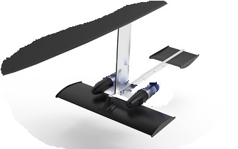
Another aspect to consider for the “dynamic” test: where to position this “cylinder” on the efoil ?
May I suggest something like this :
I know for a fact there are thousands of Experimental Aircraft Association members who are also part of MakerSpace Communities and 3D print a wide range of small to large load bearing sections of airframes out of plastic composites and several kinds of metal including titanium.
SoEFoil, the motor is not as odd as one would think … eBike, Car Hub Motors are easily available, but as they are mostly of Radial Flux design, they are diametrically not useful, a series of joined small diameter Axial Flux Rotors will be needed … Static Testing will be done in advance of STL/CAD file release … the “local” printing variances and the Dynamic Thrust values are what is of interest at the moment. There are multiple variables in the geometry that need to be understood in order to meet weight/thrust/current goals and I hope to provide all configurations with optimisations for all 3 while still improving on an open or shrouded Prop … well thats the plan … robert
When do you think you could have a first prototype working ?
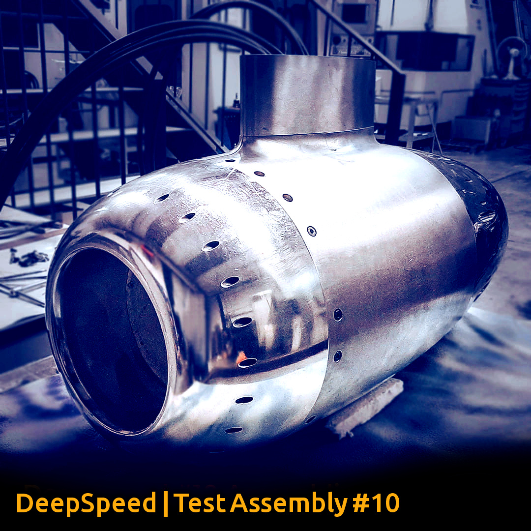
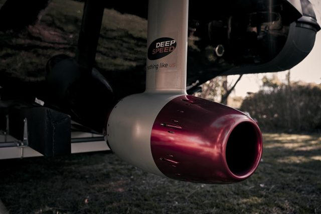
The DeepSpeed.it axial flux rotor motor below is just… crazy . A 4.5M€ development budget. It works…
After receiving numerous requests, we publish the video of the moment when the DeepSpeed #10 engine was tested for the first time in the water during summer 2019. Now we have gone ahead with the development of our engines so this test is largely passed / obsolete.
Yup … 4.5M is impressive … the degree of wake not so … I am kind of a Slow Food kind of guy … I like my cars with traction not smoking tires … so to that end I am striving for high thrust/low wake … meaning a low rotation speed with high water column displacement … I guess a kind of quiet running mode still looks cool!
Hmmm prototype date? I tend to lean towards the GEAE MBET (Multiple Build Engine Test) concept … so there will be multiple propulser builds (10-15) each with specific characteristics to test/validate. The sum of the builds define the 3 configurations, each of which could be considered “prototypes” ready for integrated performance/durability testing. A proven systems development approach … but to get real I expect 3-6m before MBET builds can begin. Hopefully some people are interested by then. I will be posting thrust simulation results for the various configurations as they are completed. (Eye Candy and hopefully encouragement to participate) Pls note that as a developer my goal is to define a Technical Data Package (TDP) that is supplemented with sufficient physical test results to interest manufacturers interested in licensing for production … the plan?
SoEfoil, like me you like to illustrate concepts … As far as Propulser/Wing/Strut configurations go … I am thinking of a single Center Body with twin tail plane booms outside and below the propulser wake … (worked on some previous aero vehicles) I should have a GA DWG sometime tomorrow (scaling for eFoil suitability is not behaving nicely)
You should love the French project with an oscillating axial membrane around a cylinder that imitates the manta ray skin oscillation around a … round surface… Target speed 60kmph, zero wake, low noise … today 2kw = 5CV gas engine… very sustainable…
Hi there, I am new to this forum and really enjoy reading about all of your work. Truly impressive, the quality and dedication that you guys are putting into developing this great new sport.
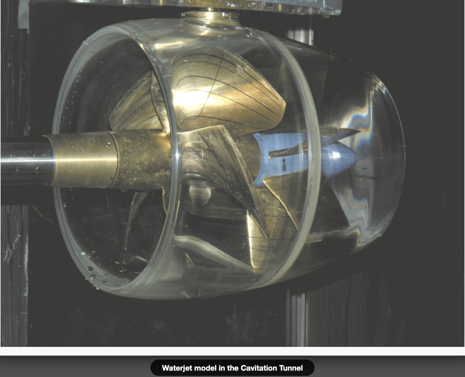
Maybe an interesting propulsion system with regards to safety to further investigate is the so called ‘Voith linear jet’. For sure a lot safer than an open propellor. Jets or pumps are as far as the marine industry knows until today less efficient than propellors at lower speeds but this one to my opinion is probably a very interesting one as it is nice to incorporate into a foil.
Links to look at: Waterjet | SVA - model institute that did a lot of research http://www.m-schmiechen.de - a lot of theoretical papers on waterjet propulsion in German and English.


 still looks cool!