hi every one , i wanted to thank you all of you for the great pics and ideas, i am thinking about my build for almost a year now and with christmast coming out i offered myself some staff…
i will try to update this to a final test in may 2018 hopefuly and apologize my english
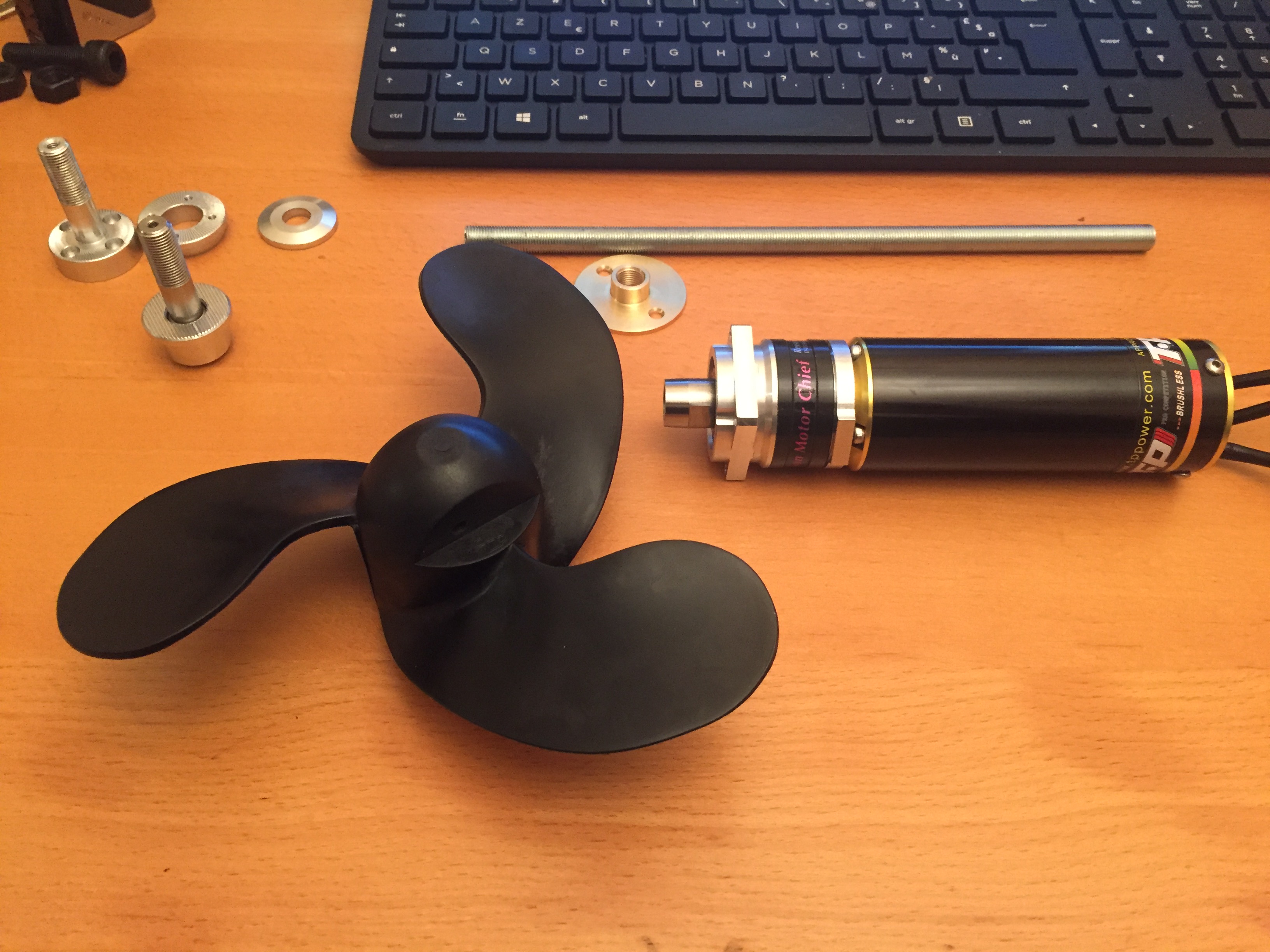
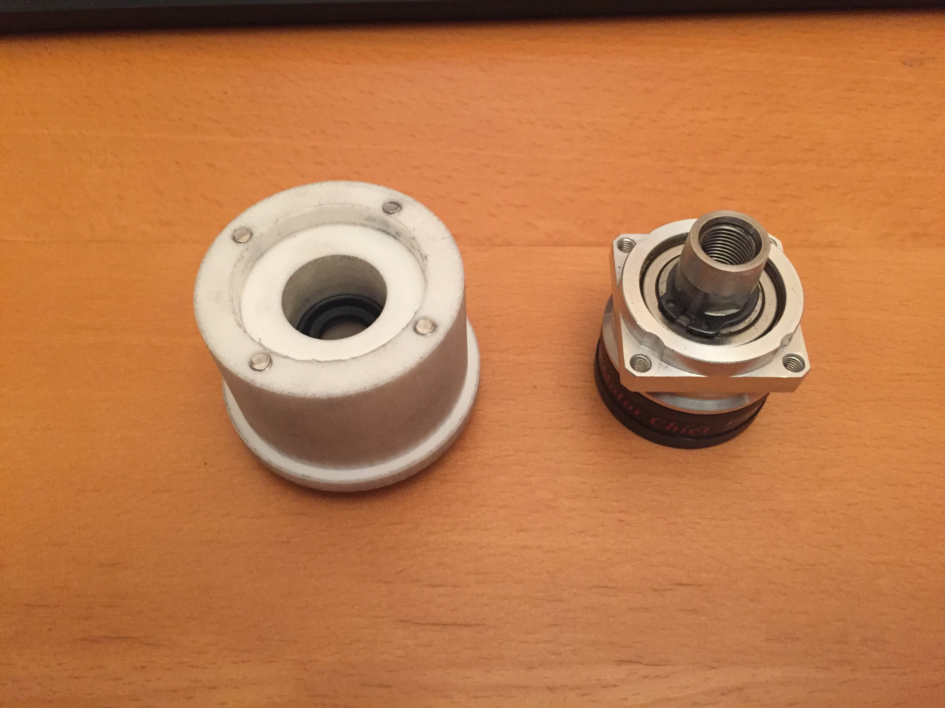
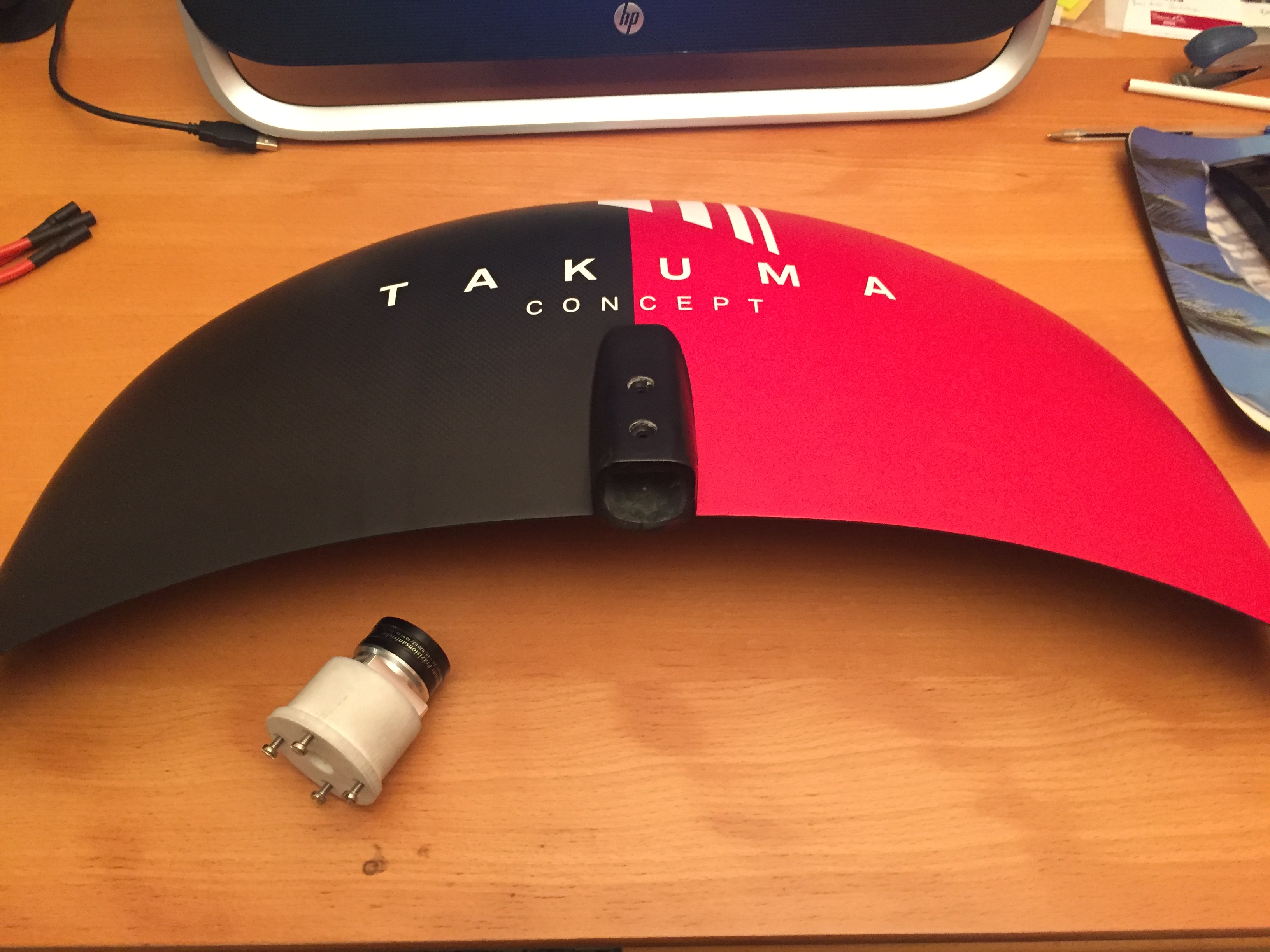
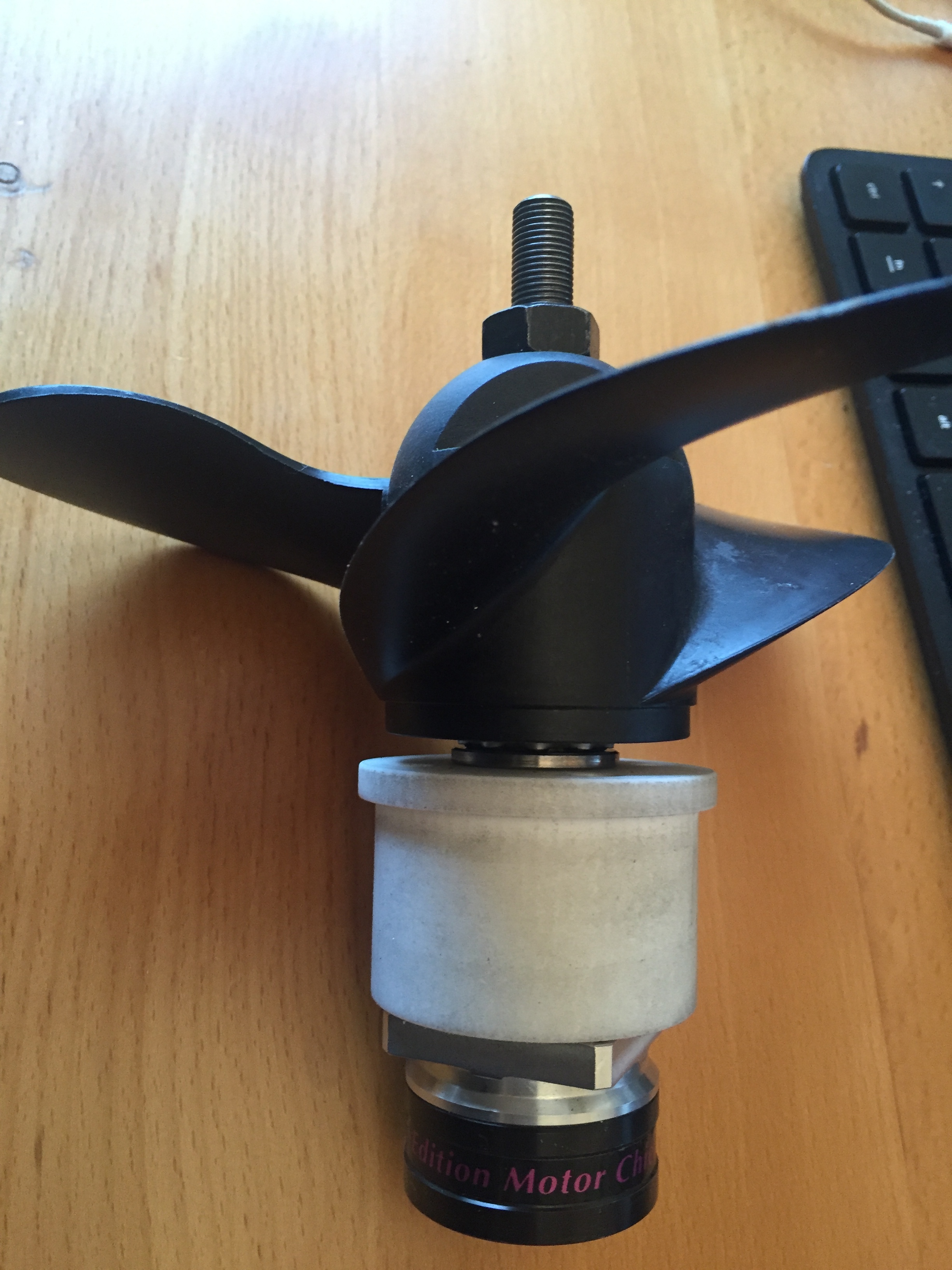
thank you, yes the tp power motor is 40x105mm without shaft and the gearbox 38.2x34mm but the edge is 47mm in diameter , i will go with a 55mm outside and 50mm inside tubing but it can be done with a 45/40mm tube
propeller is 49mm
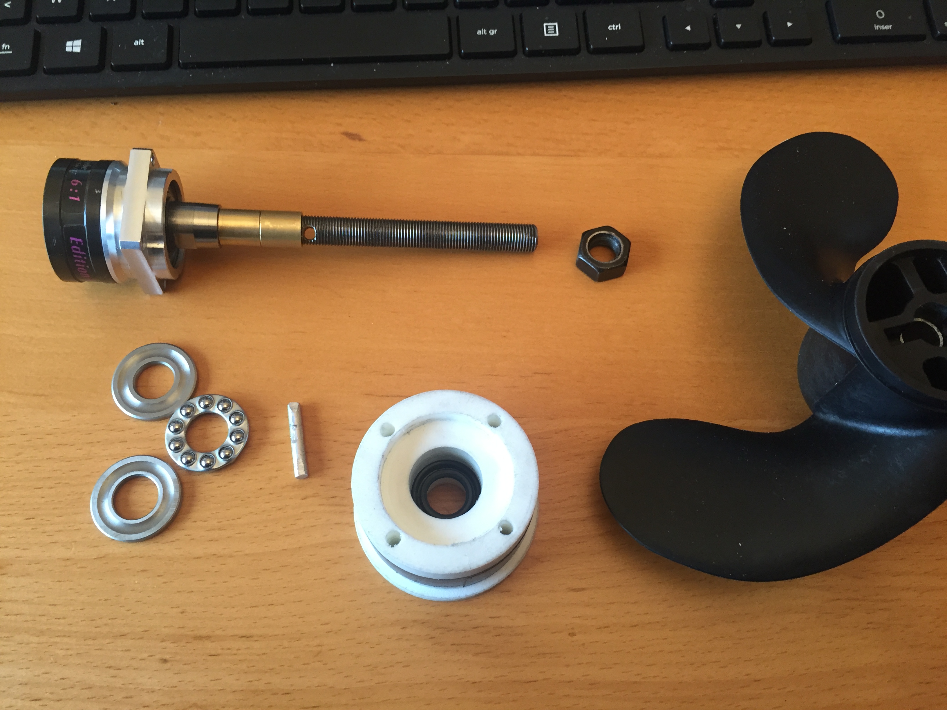
i am just trying to figure out a way so the shaft (m10x1) will not unsrew and how to put trust bearing: this gearbox is made for airplane so pulling is not a problem but pushing might be
Thank you,
For the tubing not sure yet if i will use 40 or 50mm , the propeller is 49mm …
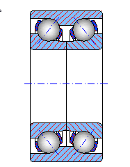
Mike: yes chief has angular bearing, needle for the super chief , I am more worried for the small “clip” that hold the shaft on the bearing outside , inside the gearbox it is larger, all the trust will be on this 2mm ring clip outside if I am correct , I will take the gearbox apart to check
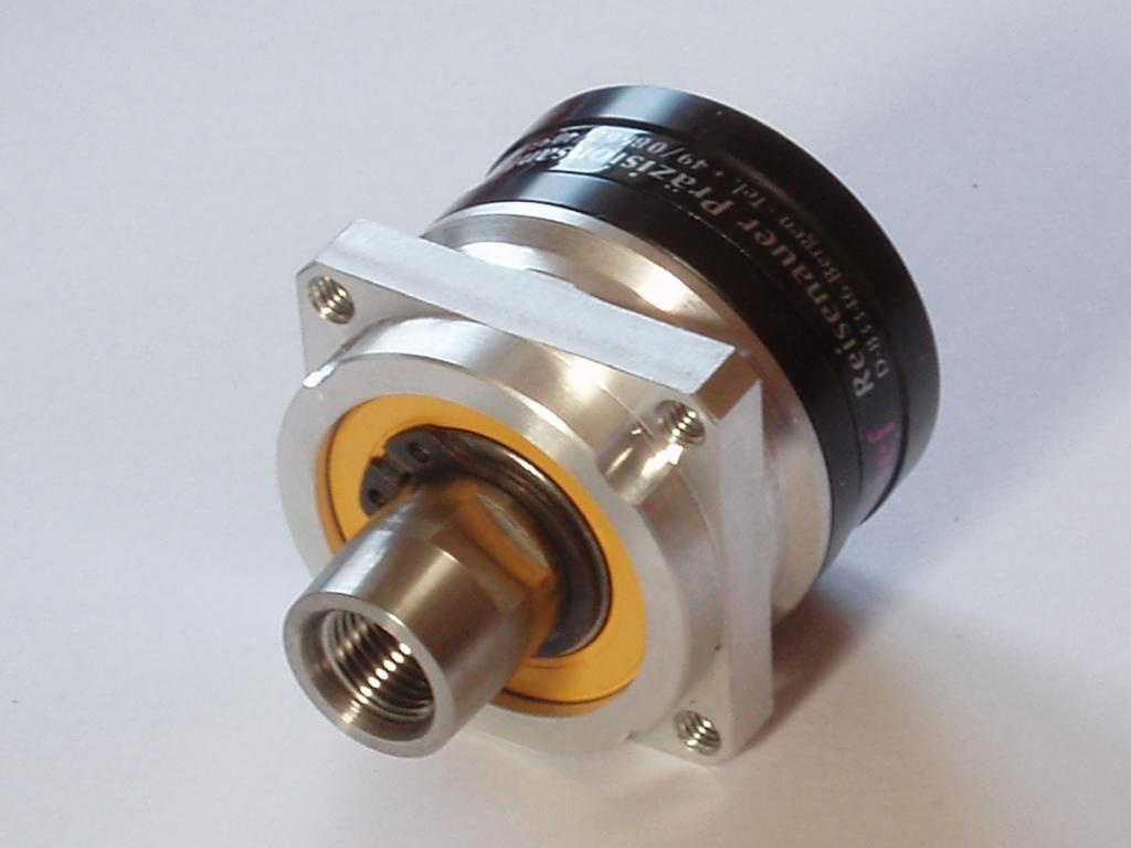
All the load from the propeller to the shaft will go on the black clip ( with two little holes) on the bearing , this gearbox is assemble from the back , i may be wrong but i prefer that the trust goes on the frame off the gearbox and the tube , no? Airplane ok , boat ?
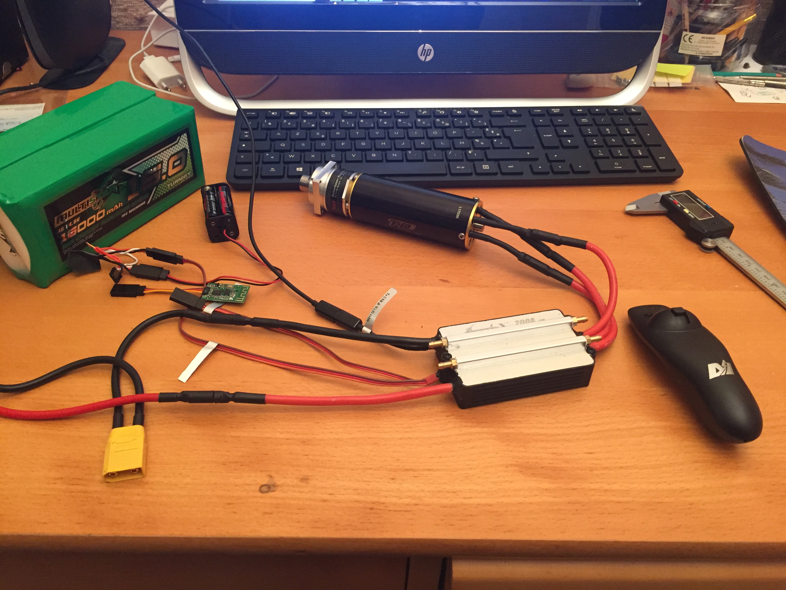
got 8x 16000mah multistar ( good deal on them now )
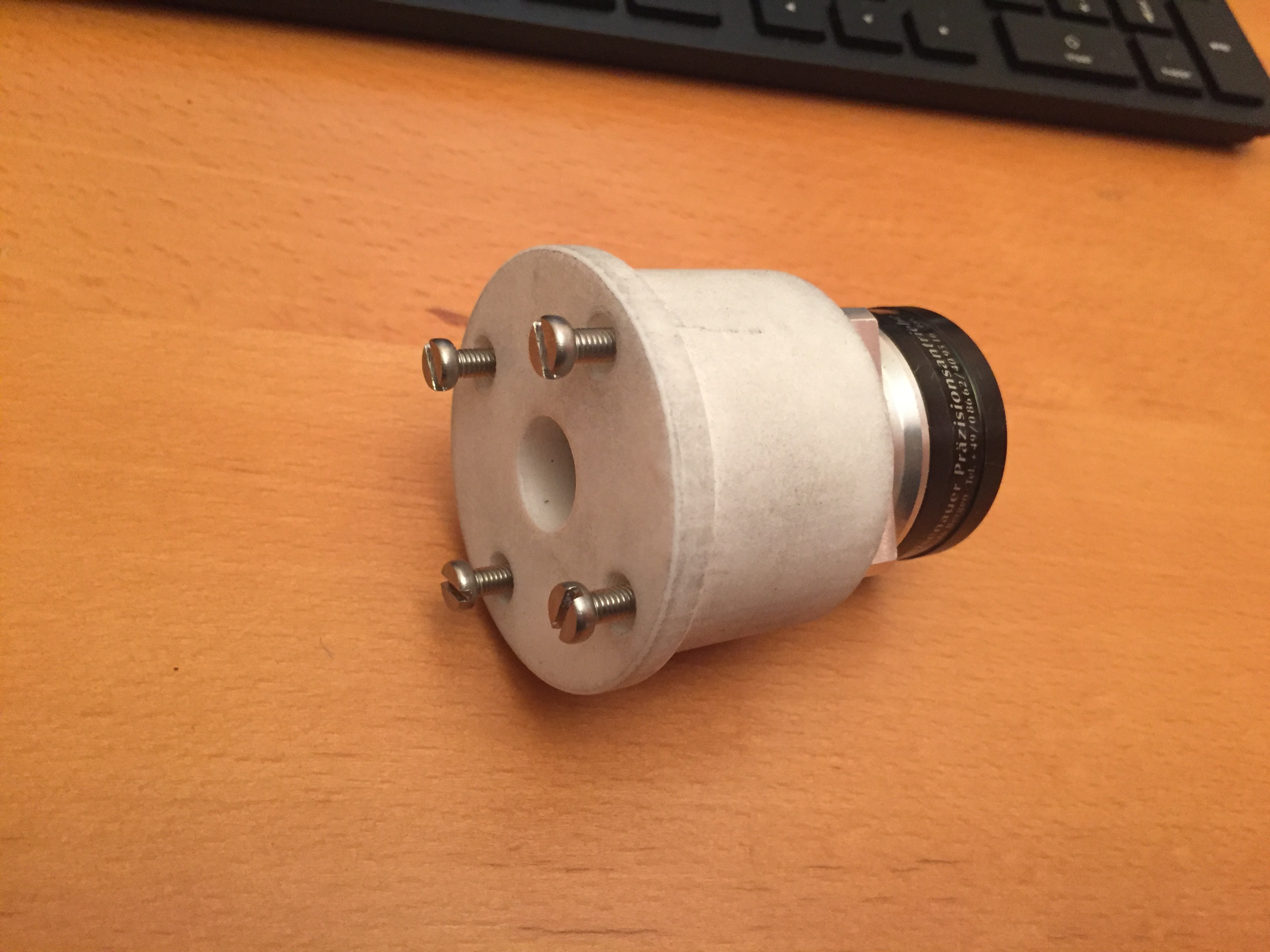
and sent my first 3D stl file to print (gearbox /tubing mount) will see… this is the first time , never did cad before , took me some hours… but i am very happy
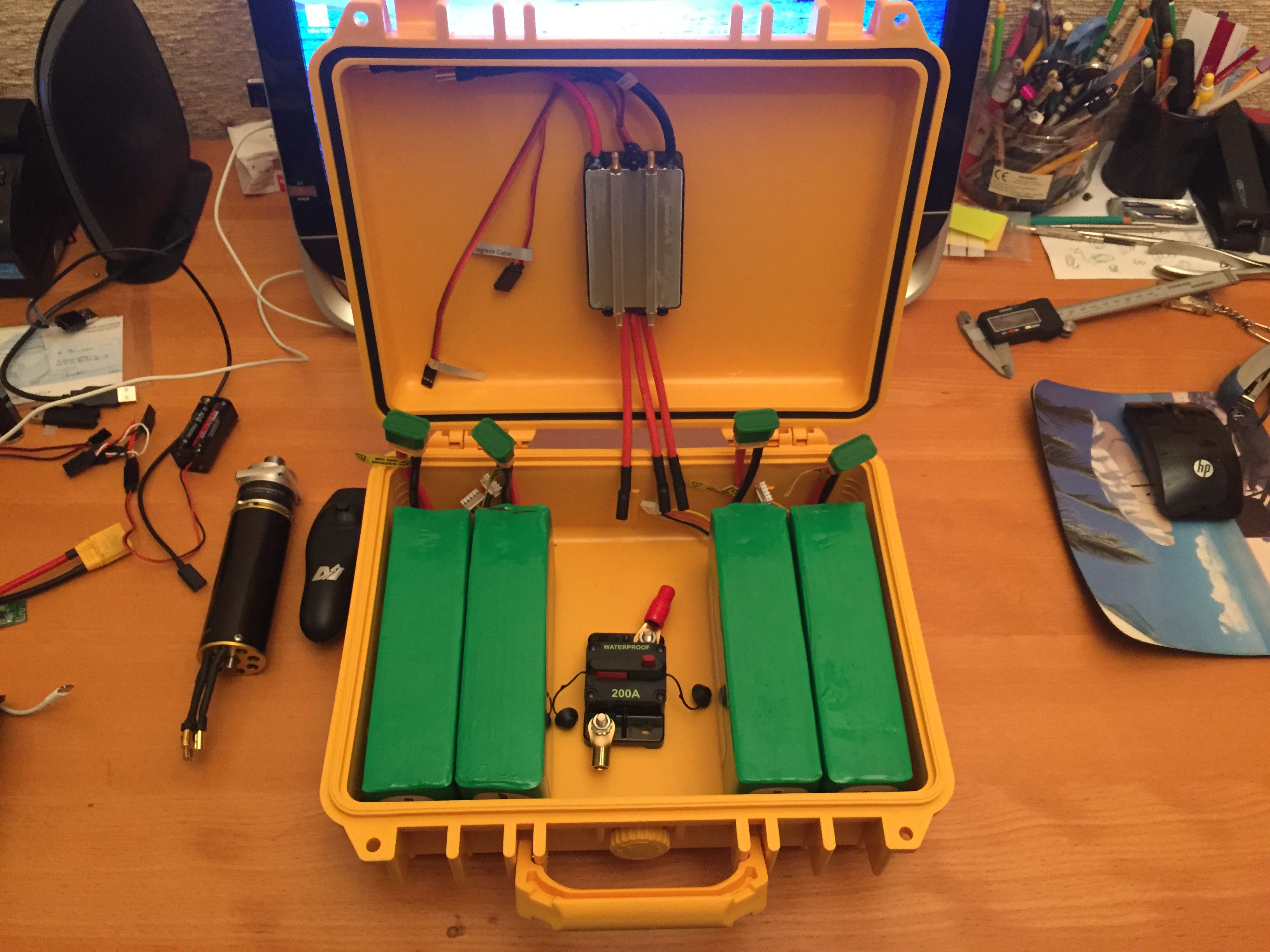
Getting there! Did you use the ‘waterproof 200A’ circuit breaker for your test run? There has been talk of this circuit breaker not actually being able to the current we require. I have a similar 130A unit but not tested.
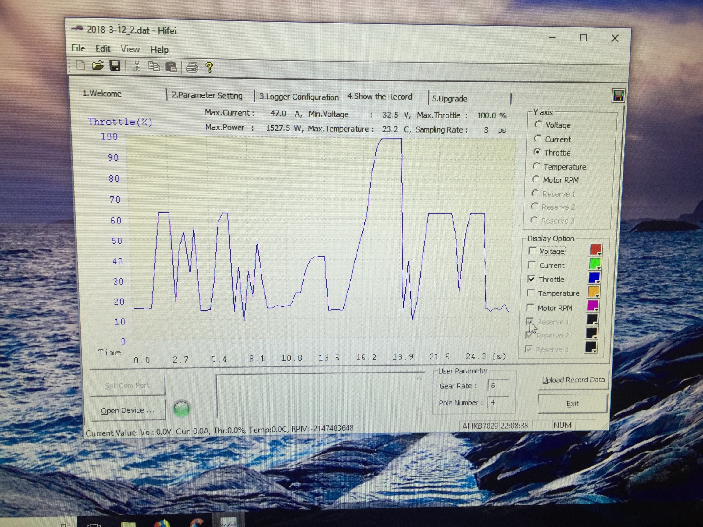
not wired yet, just test the motor and the propeller in a bathtub,i cannot hold it, push pretty hard, i need the foil to test at max power, this circuit breaker will be wired in serie between two pack of 4s 32000mah so it will see max : 16.7v and ±100A …
got it from a quality dealership on the back it is written “made in taiwan” so it may work…
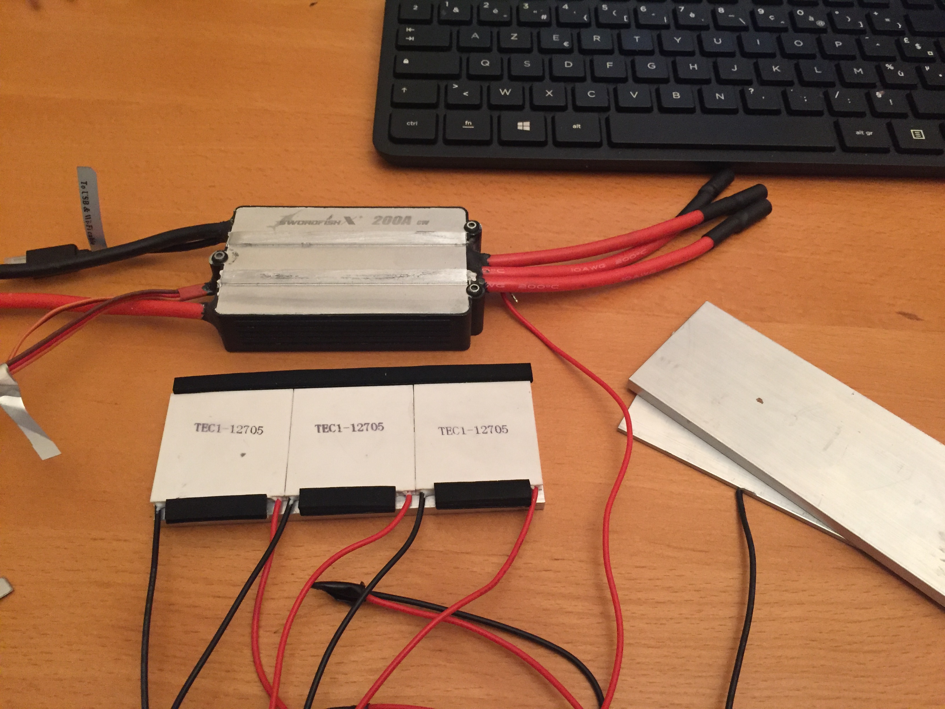
well i am on the cooling issue, just try the peltier module , pull 3- 4A , one side cold other side hot (very hot i burn my finger), as long as you keep cold the hot side , it is working but when you stop or turn it down , the heat transfert everywhere, so i may do something wrong but i am not happy with this solution
I don’t see how the Peltier is going to help here. Peltiers work by making one side cold and the other side hot. I assume that you want to stick the cold side onto the ESC. This will cool the ESC, but what happens to the hot side? The Energy there needs to be dissipated outside.
The Peletier does not really cool. It is only like a pump for thermal energy. It takes the energy on one side and moves it to the other side. That other side needs to be outside of your ESC case.
Thanks for sharing your experiments. I like your build, because it seems to me like it will be an easy beginner foil. I might have some advice on why your peltier devices get so hot. I have not tested your specific type, but I have done some prototyping with peltier devices in other projects. Typical peltier modules have a COP < 1 for any serious amount of heat moved and a temperature difference higher than a few degrees Celsius. This means if you want to move a watt of heat from the cold to the hot side you have to use >=1W of electric power. This results in turn in at least 2W of heat to get rid of on the hot side quickly. If you can not cool the hot side enough your temperature difference will rise and your efficiency suffers. If you don‘t need to cool your esc below ambient temperature it might be easier to increase thermal transfer to ambient by larger heatsinks, active forced airflow or water cooling. I didn’t find a perfect datasheet right now to help you estimate your setup, but this example peltier datasheet I found online might give you some more ideas. You can calculate the input power from the device test graphs and compare it to the amount of heat moved. This will probably be much clearer than my description here. In any case much succes with your build and development.
Edit: @MaxMaker how can you type so fast
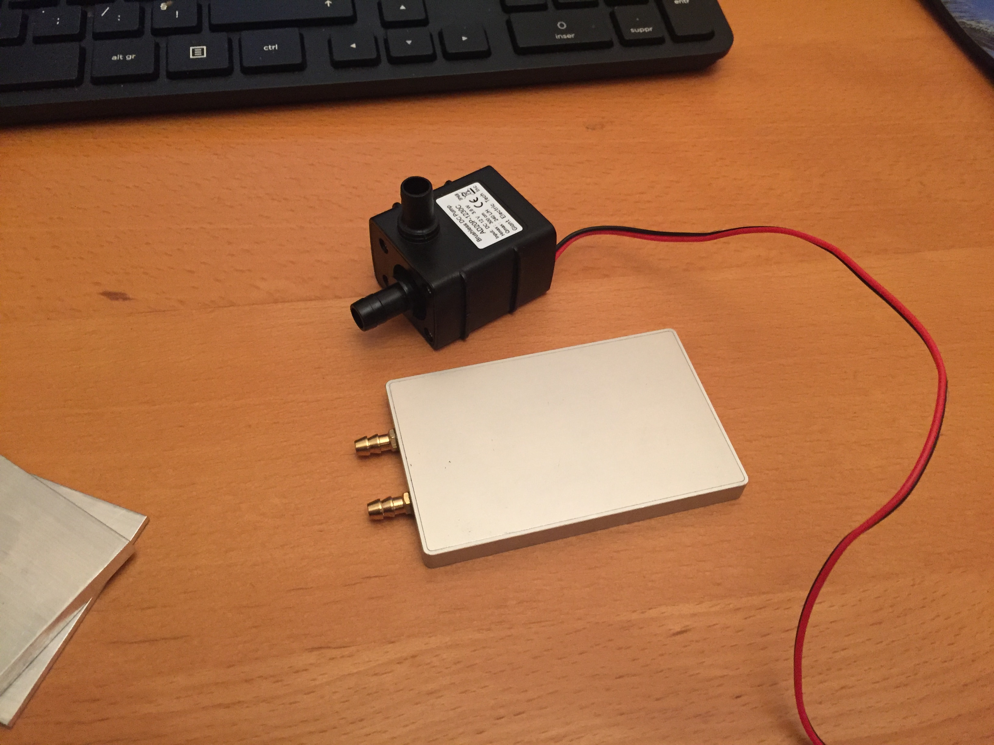
the pics show just a part of the setup , i tested with a heat sink on the hot side , 2 plates alloy 5mm 200*200 , that was supposed to be on the top of the case , and yes outside, but before i cut a hole in the case i tested and realized that the heat sink outside need to be a lot bigger and yes with the foil moving (forced airflow) it might work but when you stop, the top gets very hot and finish by heating everything, need a fan as well i guess, so the all thing will take too much place
pull 130W so i guess i needed 300w of heat dispersion on top of the case…
i made a couple and buy some, but it was never straight and i had some vibrations
first test (in the bathtub) i just put 2 blots (contre ecrou) on the shaft between the prop , hold about 500W
in this set up i will glue with loctite bleue, i think it will be enough, just have to wait 12H before putting load on it, and you can always unsrew it by heating
you have to look for "pas fin m10x100, utilisé en luminaire, dispo chez casto mais ils sont creux et tordu la plus part du temps, et en construction sur des sites spécialisés en structures métalliques "
i got 1meter shaft for roof construction, hard steel (same steel as the screw from the gearbox , there is a number on top of the screw) , very very hard to drill , but prefecty straight
or put a screw on gearbox or a pin : i think it s titanium, don’t think you can drill that properly