Desolder a connector implicates 200++ C, a lot more than electronics and wire should withstand… maybe it’s just matter of undersized cable/ESC. Eventually, do solder with nasty lead-free, it melts at higher temp.
Inside the ESC I crimped the AWG8 motor side, but out of the box I use soldered xt150
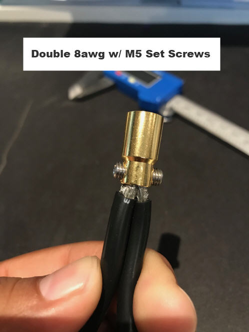
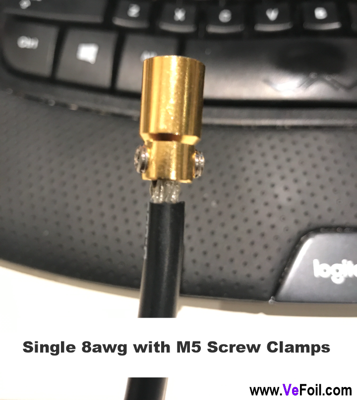
yes, its very hot, and likely poor connections overheating and/or undersized wires. I like the idea of wires being mechanically held in place via crimp or pressure set screws. I made beefy 8mm gold plated bullet connectors with two pressure set screws which works really well and they can handle 170A and a little solder they are bullet proof.
Sounds very good!, can you pleas show us? Having reliable solid connectors is very important!
i had bad experience on crimp connector on car sensor before , i always prefer solder everthing, and i say good solder, it took me some time to learn to solder xt90 and xt150, i am using a 90W solder iron and it takes heat and time to make it perfect, the silcone wire rated for 200°C sometimes melt before, on my step up on 8S i am always around 100A, the circuit breaker is warm the xt90 plug is hot but i don’t see how it can get loose, even with pics above 150A… i am not talking about impeller probably with higher amp, but still i run 8S which gives amp
this guys hold the world title for rc boat racing: the link for 400A connector in 6MM!!!
the best ,i guess, will be both crimp and solder, but it is hard to solder correctly big wires
I crimp where I can. Its important to match the wire, lug and crimping die together to get an effective crimp.
When done properly, the copper strands look like a solid core of copper if you cut through the lug.
2 Likes
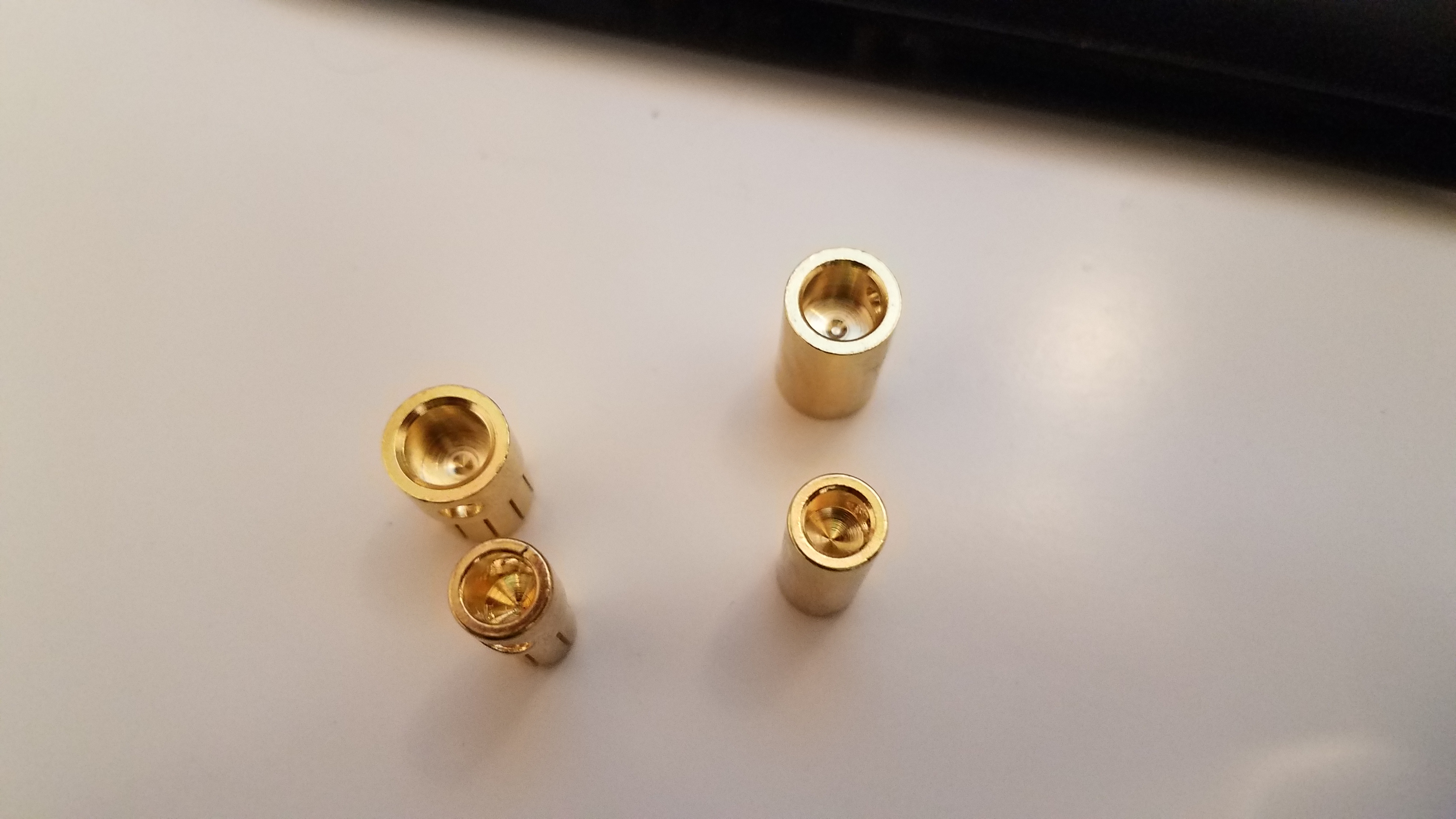
I tried several 8mm bullet connectors, it amazing how many different variations/quality there are when you buy from different sources. On the hunt for proper sized 8mm connector thats easy to plugin and unplug as some are really tough to unplug, while allowing double 8awg wires from ESC to be inserted and clamped with M5 pressure set screws, I cant pull out the wires no matter how hard I pull.
And if you put some solder inside at the bottom of connector and heat it up with wires in the ends get soldered with solid connection to bullet and M5 clamps lock it in with tight friction fit connection.
1 Like
When I was trying to buy my replacement ESC. Many of the high power ESC’s had those dual input wires. I concluded they must be for aux capacitors to smooth the input power at high demand. Am I wrong? Were you able to get all the #8 strands from both wires into that connector?
Yes both esc wires are for current, and both fit in the end perfectly 
Great idea! Did you solder before or after you set the grub screws?
1 Like
Is that a 8mm connector with 2x 8AWG cables inside? Good effort.
1 Like
Yes, two FULL 8aweg wires fit in there, and if you take the motor wires which are smaller awg, you strip a longer section, then fold it and put then use two set screws, then solder motor wires in there. Works amazing for high current and now worries about desoldering or wires pulling out
Did you see my post below Hiorth on how I did the 8mm connectors?
Got a quick question regarding escs. Lets say its rated 100A. Is that considered as an input current or motor phaze current? Or is it just marketed as input current with(out) phaze monitoring/limiting? The way i understand it, esc is basically dc-dc switch so i am guessing there is different amount of amps on “both ends” of esc. Could that be a reason for some of unexplained destruction scenarios? I know there should be spec sheet but we all know not every1 shows it.
On the vesc + metr for your cellphone you can track battery and motor current, you will see that motor phase current is often much higher than battery current.
So I think that the rating is battery/input current and that the high phase current driven by our large props may kill esc’s.
Still there is probably many other ways that is more likely to kill esc’s. Water ingress, poor soldering/connectors, uneccisary shaft friction, mismatch prop size, fake esc’s, no heat cutoffs, poor cooling+++
Our seaking is still going strong (1.5 year, 80h+) , I was out in the surf with it the other day. We have also done hydrofoil tow ups with it
2 Likes
Phaze currents strictly depend on the motor type wiring right? (If we disregard copper/friction losses, “human error” and possibly bad esc build aka ideal scenario?)
This link is dead unfortunatly
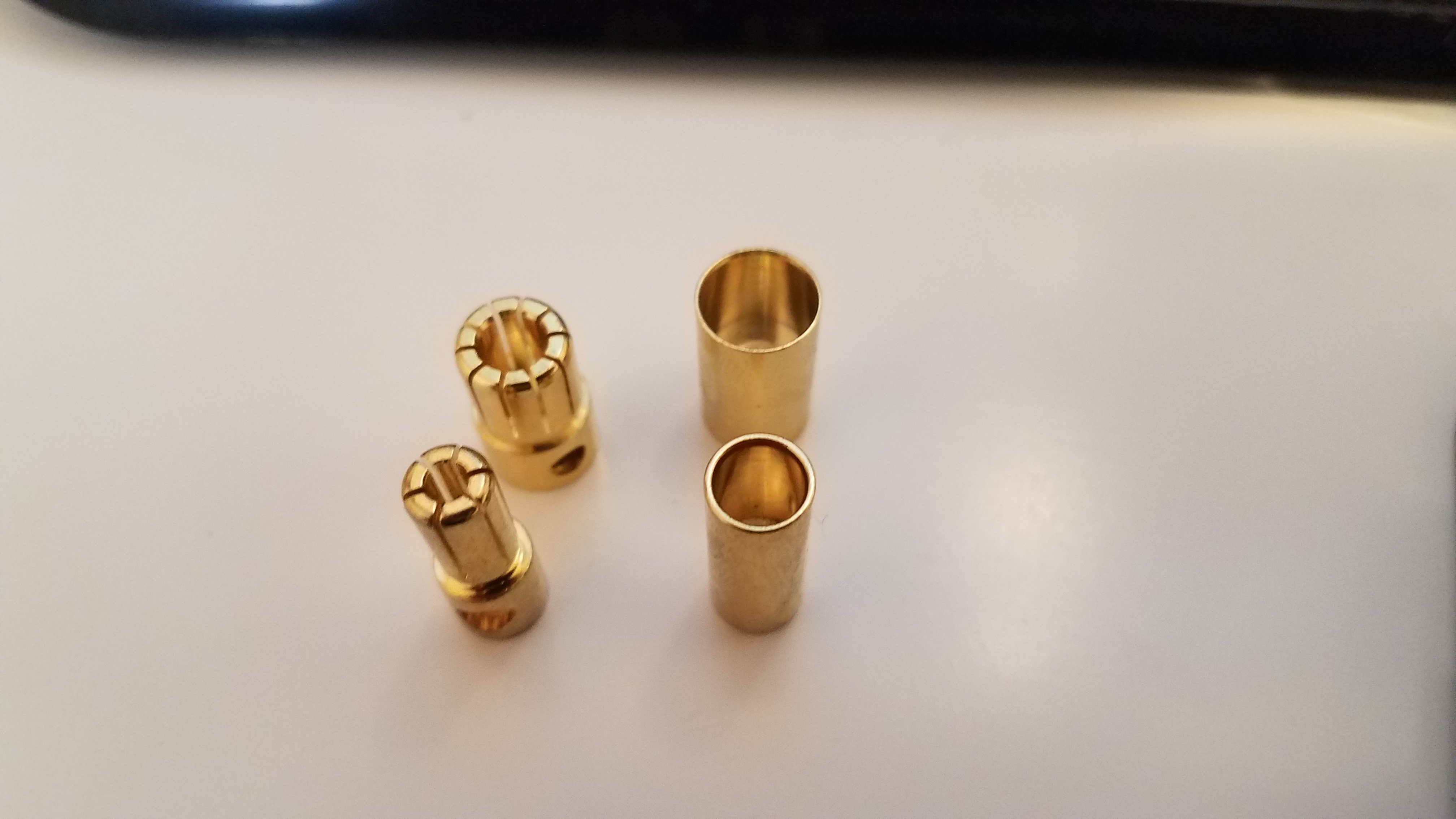
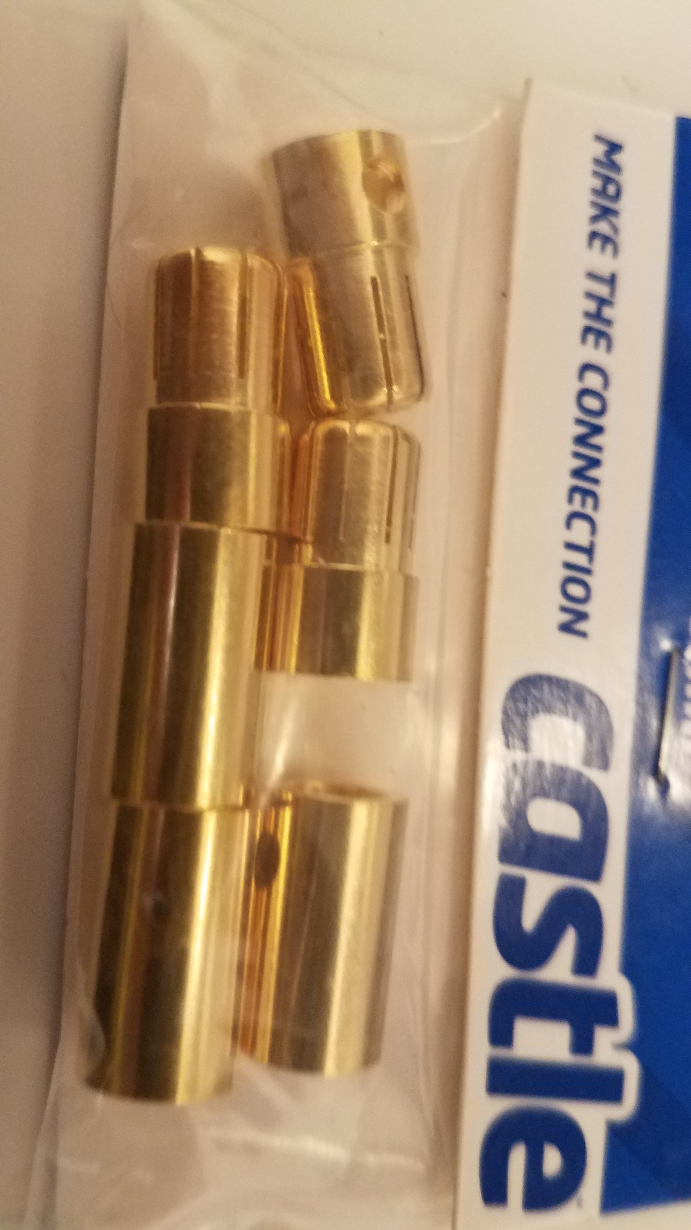
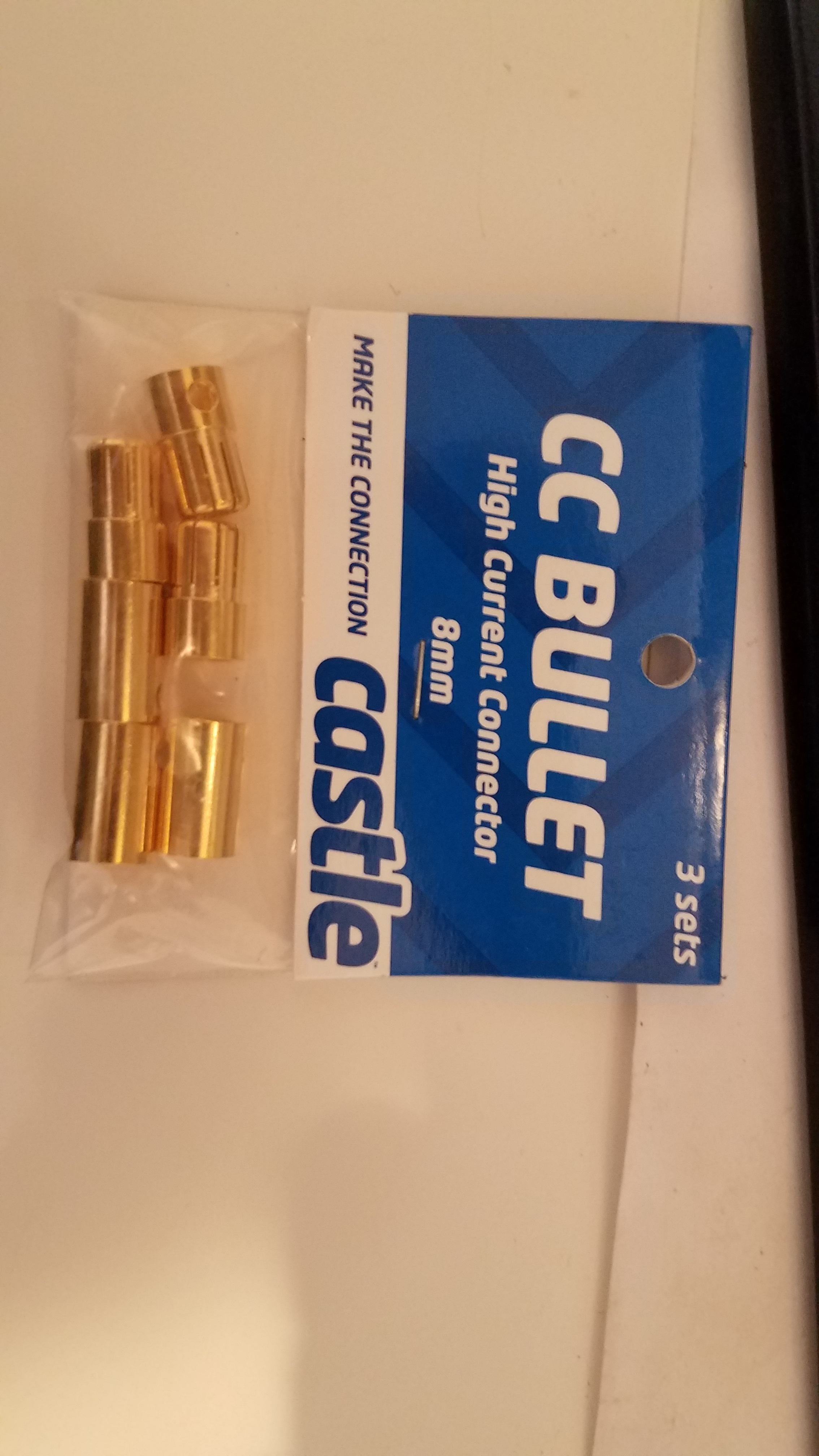
Option: Castle Connections 8mm Bullet Connectors
Claimed to be 300 A continuous rated, Amazon, 15 bucks per 3 pairs.
5.5 mm version shown with the 8mm for reference (rated at 170 A)

I was talking to the guy at Reacher Tech who shed some light on the situation.
Basically its the way Flier mislead unsuspecting customers like us.
For example, my 3-16s 320A ESC is not rated for both at the same time. Its 320A rating is on 3s! so its only rated for around 68A on the 12s im running.
This might explain why my 68A 12s setup is running ok when I pull 50A constantly but guys pulling higher amps direct drive etc, are blowing them up.
Seems to make sense to me.
Support from Flier told me that I should not exceed 120A continuous current on my ESC 3-24S 240A.
So I hope it will survive under load…