Yeah, but I also think that most riders at the moment have to place a lot of weight at the tip to counteract the moment from the back wing. That is because most wings are designed to be pulled by a kite or a boat, so the force is acting high above the board. With the motor, the force is on the opposite side. So I will probably build new wings one day that are optimized for an efoil.
2 Likes
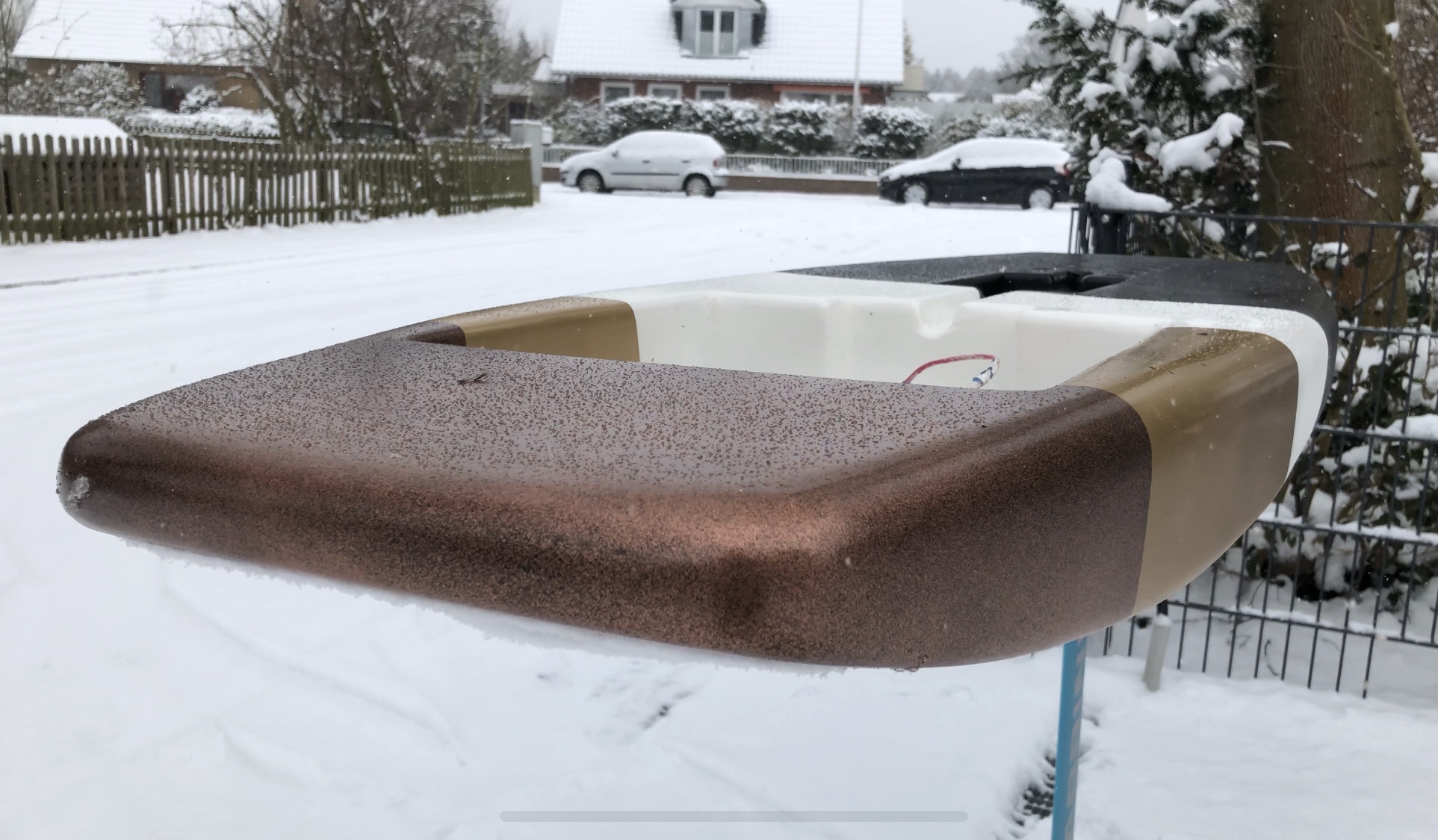
The paint job is almost done. There are only some minor touch ups left. Then comes the clear coat, but first I want the paint to cure for a few days.
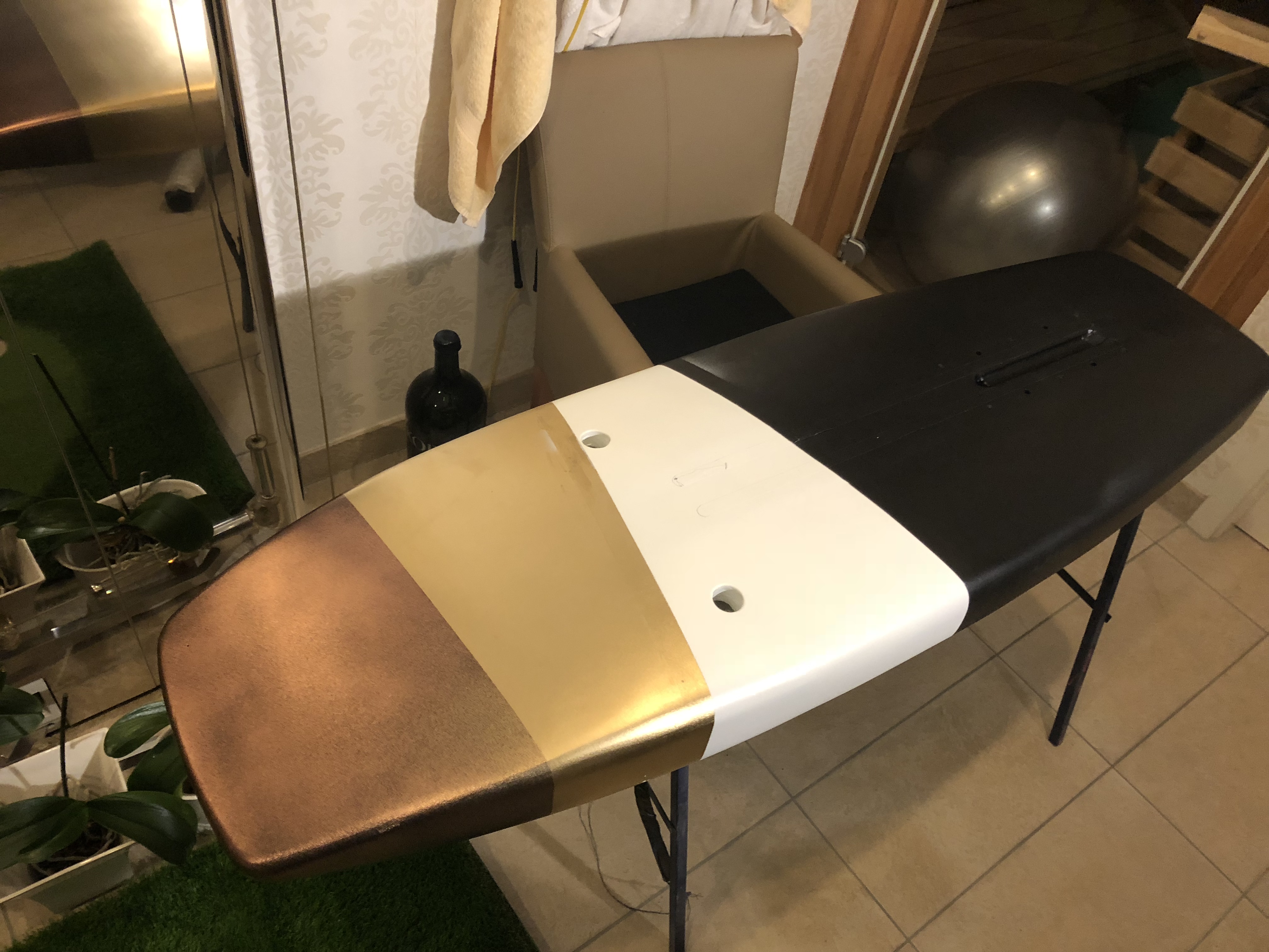
The bronze on the nose was a bit tricky. I couldn’t buy the right colour, so I used metalic copper and mixed it with black. It took a few tries until I got it right.
11 Likes
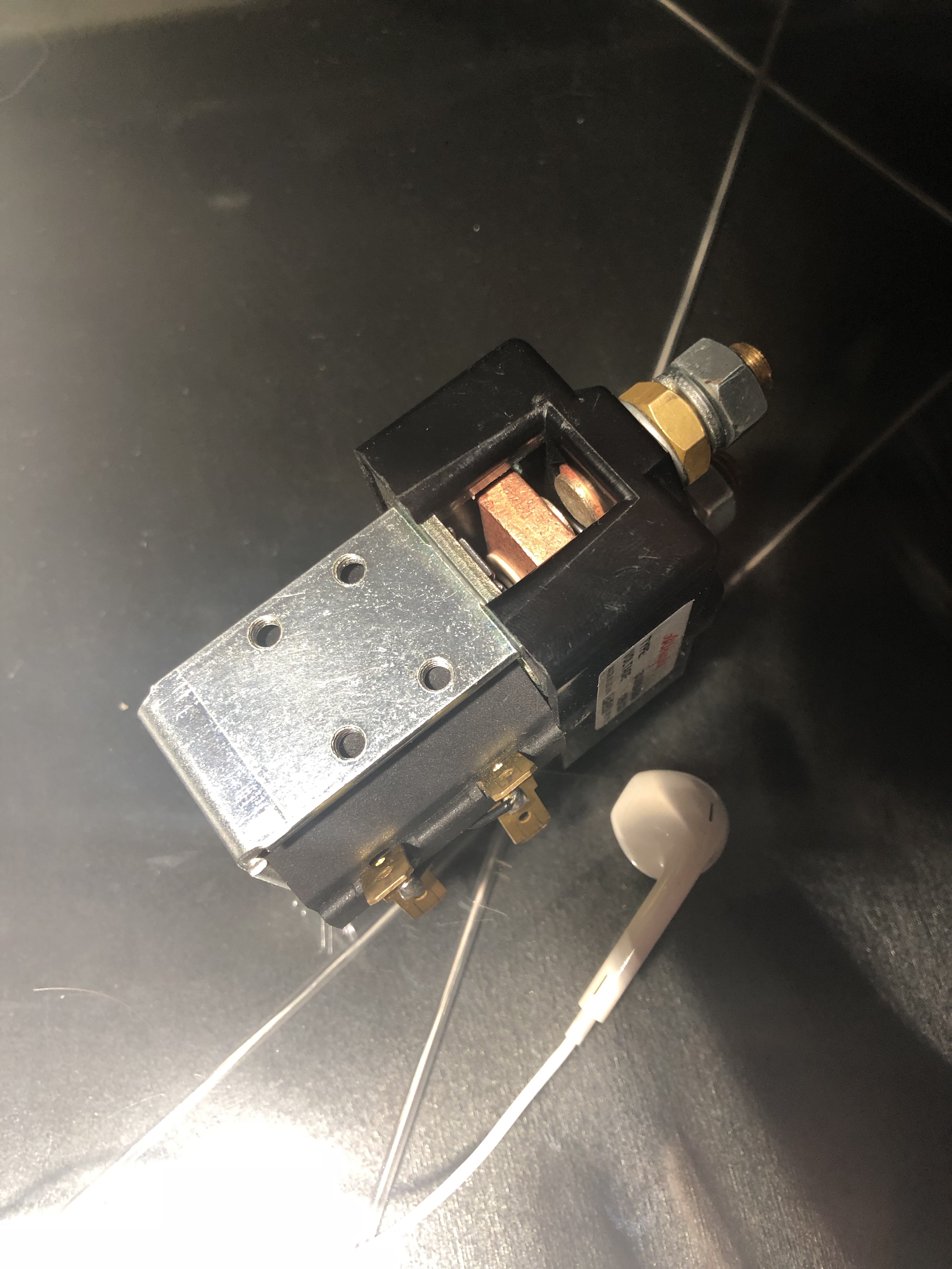
That’s quite a hell of a solenoid! Seems an Albright single contact. We use those at work for powerfull DC thrusters and winch motors.
For Lipos and ESC I’m still concerned about the huge sparks they trhow and the effect of a sudden break up under load over ESC Mosfet… but only by trying you can find out. Finger crossed.
It is an albright and they use it a lot for forklifts in case you want to shop one on ebay. Solid build quality.
I will add anti spark somehow. At the moment I am thinking about adding a secondary relay that only connects while the big relay is connecting. This would be controlled by an Arduino. After it is connected, the secondary relay will disconnect again, so it doesn´t pull any current. This will all happen in 1 second or so. Resistor specs are welcome!
short: A 50 Ohm, 5W resistor is good enough. If you want to build a compact device a 3W resistor with 47 or 51 or 56 Ohm resistor will be fine, too. Search for cemented wirewound resistors.
Examples: 5W or 3W or search your favourite distributor ![]()
Your second relay can be quite small as the peak current is obviously only 1A.
Why I would choose a ~50Ohm resistor:
To calculate a resistor you can use this website: https://www.allaboutcircuits.com/tools/capacitor-Charge-and-time-constant-calculator/
I have 8 x 480uF on my ESC, the new Vesc 6 has 1360uF of total input capacitance. If you decide on what ESC to use, look at the electrolytic capacitors on the input to find a closer value. I just assume 3000uF to be on the safe side. That is the capacitance you have to charge with your antispark mechanism before you connect your big relay. Assuming 50V battery voltage I just trimmed the resistance value until my time constant was in the right range. After 5 times this constant your capacitor can be assumed to be fully charged. Reading your post I assume your goal ist to be faster than one second. With 50 Ohms as charge resistor your max charge time would be 0,15s*5=0,75s. Peak power is 50W, but you probably only need a 5W resistor as after about 0,2s the power is below this value and the power dissipated is quite low (<4J). This datasheet has good graphs startig on page 5 for what shorttime overload wattage is acceptable. As all assumptions above are quite conservative a 1W resistor will work, but the cost is not significantly lower for a one off device and you probably don’t want to order twice.
6 Likes
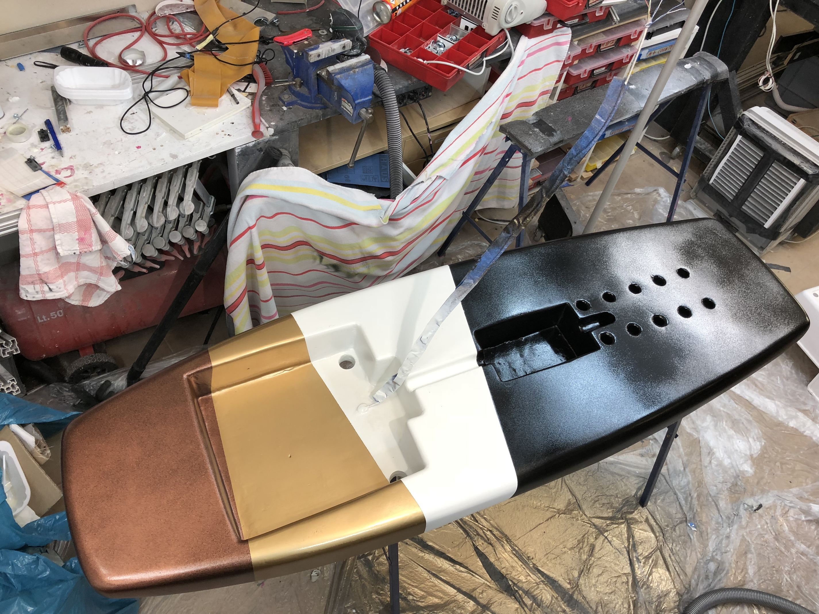
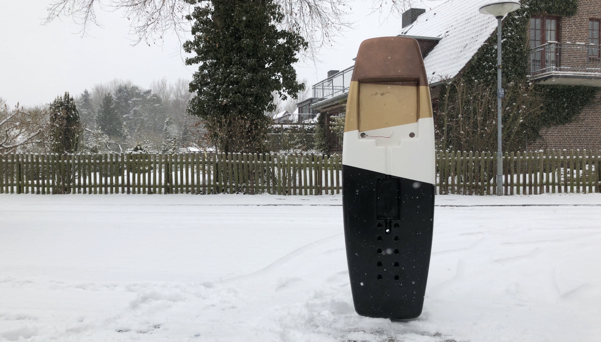
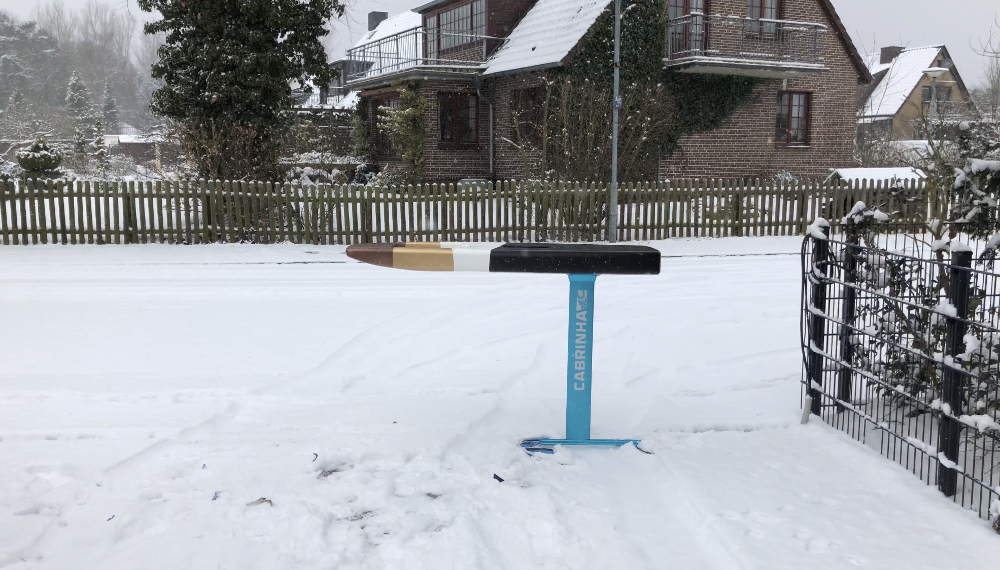
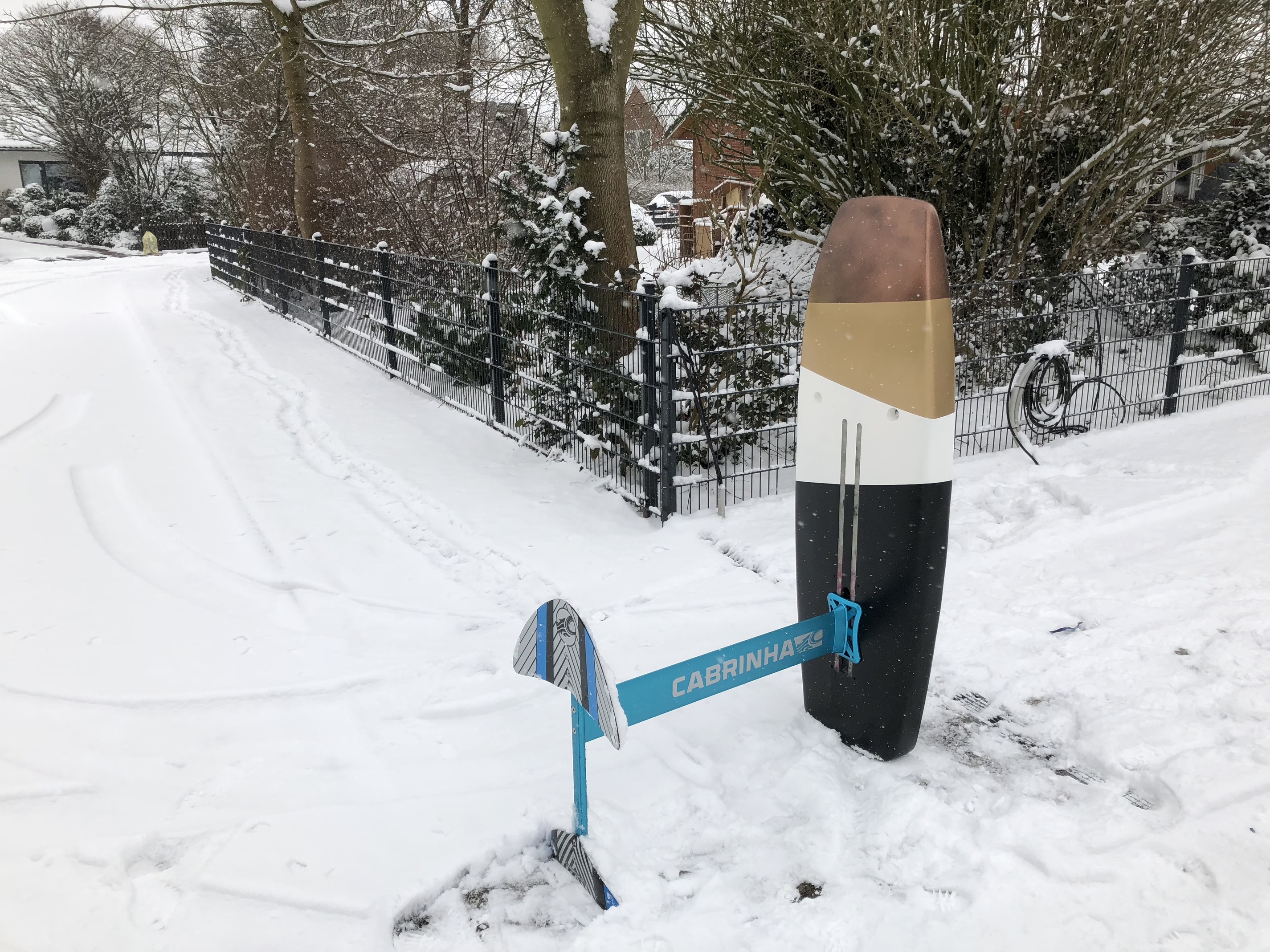
The paint is done. A few coats of spray paint followed by clear coat. The texture is a bit more rough like it was supposed to be. Somehow the paint didn’t form a nice even wet coat. Its looks a bit like a fine orange peel. I could sand it with fine sandpaper and then polish it, but I think I leave it as it is. If I sand through the paint there will be spots to repair which will just add a ton of work.
It weighs 3.8kg at 150x50x14cm.
7 Likes
So that is a volume of 105 liters, correct ? With a concave shape, as 50cm width must be the max width in the middle…
So that must be slightly under 100 liters all in all
I hope that you do not weigh as much as me 
Actually its just 70l the cavities and the thin nose take out a lot of volume. I weigh 83kg. 90kg with my vest, wetsuit, helmet and shoes.
15 kg hardware + 90 kg of you… That is 105 kg for a 70-liter board. Ouch.
You’d better start going on diet 
1 Like
Looks fantastic, congrats on the high quality build.
Are you planning on installing a hatch over the compartments?
Thank you. The compartments will be filled with a waterproof camera case and a waterproof aluminium enclosure for the ESC. They will be strapped in with nylon webbing.
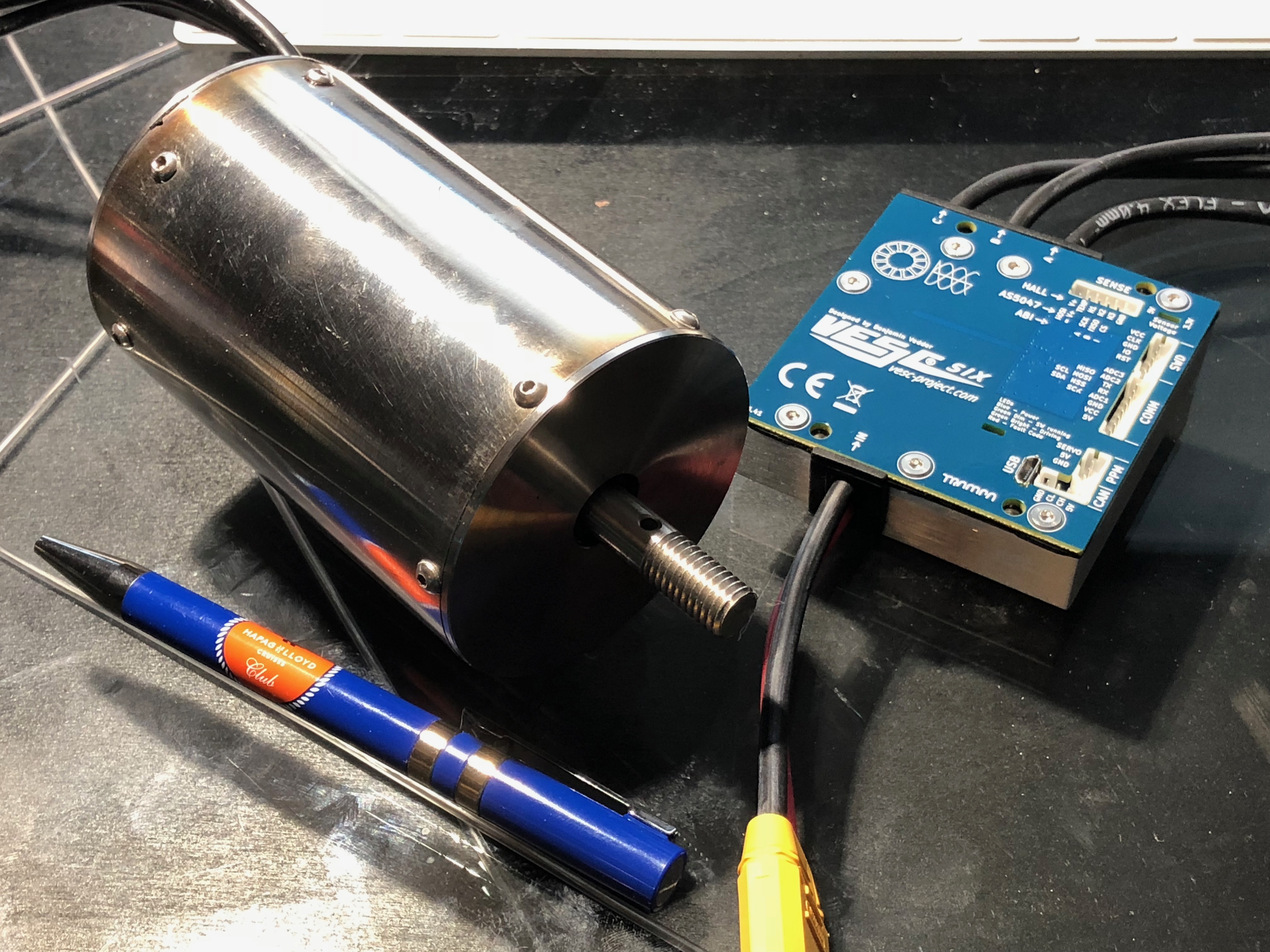
So the VESC 6.4 arrived today together with the waterproof motor from Alien. I am not sure if the motor will be powerfull enough, but we will see I guess. Same goes for the ESC. I chose it because it is small and has a lot of safety and data logging features. It is also very suitable to mount it to a large metal heat sink. Something no other ESC had.
It looks like the motor is sealed with silicone everywhere. I don´t want to take it apart. Bruno said that it is an outrunner and that there are cooling chanels somewhere. No idea how it looks like on the inside. I also don´t know if there is a thrust bearing. Bruno said it is made for taking the load of a prop. He doesn´t really answer the questions that you send him.
The cables on both are just 12AWG. I have 8AWG for everything else (which is bigger). Do you think the cables on the motor and the VESC matter much? They are short and submerged in water anyway.
Congrats, it arrived! Looks nice!
Is there a temperature sensor inside the motor? The Vesc has a motor temp input to protect it from overheating. I think it has no water cooling inside.
I would take these steps:
- Take measurements with the vesc to document the resistance, no load current and Kv. Swap motor phases several times to be confident.
- Mount a temp sensor to the winding, get some hints how to take it apart maybe from other users or the manufacturer. Ask also what the temp limit of the magnets is. Program the vesc to limit motor current between around the magnets temp.
- Mount a prop, test it unsubmerged and uncooled, get some real time data from temp sensor at different phase current settings.
- Unmount the prop, heat up the motor to e.g. 60°C in an oven statically, so all components inside have the same temp. Submerge it and let it run with no load current for some minutes with temp data readings.
What can you do with this data?
From the phase resistance and the current you calculate the ohmic losses and add the no load current to get the powerloss which is produced inside the motor. Together with the temp sensor reading you get a heat up curve and can estimate the thermal capacity. From the 4. measurement you can estimate the thermal resistance from winding to outer surface.
Try to set up a simplified thermal model with capacitors, resistors, voltages(equals temp), current sources (equals powerloss) using Matlab or simply Excel by feeding it with real time data and the simplified thermal model and a fit algorithm to find the parameters.
With this thermal model try to simulate some scenarios with startup processes and foiling phases and pauses.
If its overloaded by permanent foiling, forget it,
if it is overloaded by frequent startups, use the temp sensor,
If it is never overloaded go flying.
About the cables. I think the vesc6 has AWG11 wires which is on the boarder. Maybe you can resolder with bigger ones, but that costs your warranty or keep them short with a massive plug or solder interface. The motor wires you cannot change, its too risky.
Good luck!
3 Likes
No sensors inside. I would love to add one but I have no idea how to open this thing. It sounds stupid, but everything is covered with sealant. If I apply force to anything, I don’t know weather I am pulling on the sealant, magnets or bearing assemblies. Ill try.
Did we not have photos somewhere where it is in pieces?
Here is the video of the board building process. The motor will follow next.
16 Likes
Max, the video is awesome!! thanks for that.
I’m sure just filming and editing is a huge chunk of work, not to mention the epic work you put into the actual board, wow!
2 Likes
Yeah it is. Thank you!
Hi Max !
I watched your video: Amazing job here with the board and videomaking ! Such a professionnal work, very inspiring !
Thanks for sharing !
Are you also sharing the CAD file of the board ?
1 Like