I thought I’d use a new thread to document a build, from the word go, based off a @pacificmeister’s excellent plans and the info contained on the forum. By documenting it from start to hopefully finish over the next couple of weeks, I hope to help any other new builders, as there’s a wealth of technical information on here. I’m coming at this from someone who did a bit with RC stuff a few years ago, but completely non technical and new to the CAD/printing/mechanics (I’m an anaesthesiologist!).
The build is essentially taken from the parts from the PM CAD build sheet. For other aussies, I’ve had to use ebay and bunnings to supplement the stuff that amazon won’t ship to Australia. I’m using a Sindoh DP200 3D printer to prototype the parts before assembly in PLA, I’ll most likely do the final version in ABS. I’ve spent the last couple of weeks sourcing the parts which have started arriving and I’m keen to get this going before the new year. Haven’t decided on a board yet, and I’m waiting for the foil from alibaba to arrive.
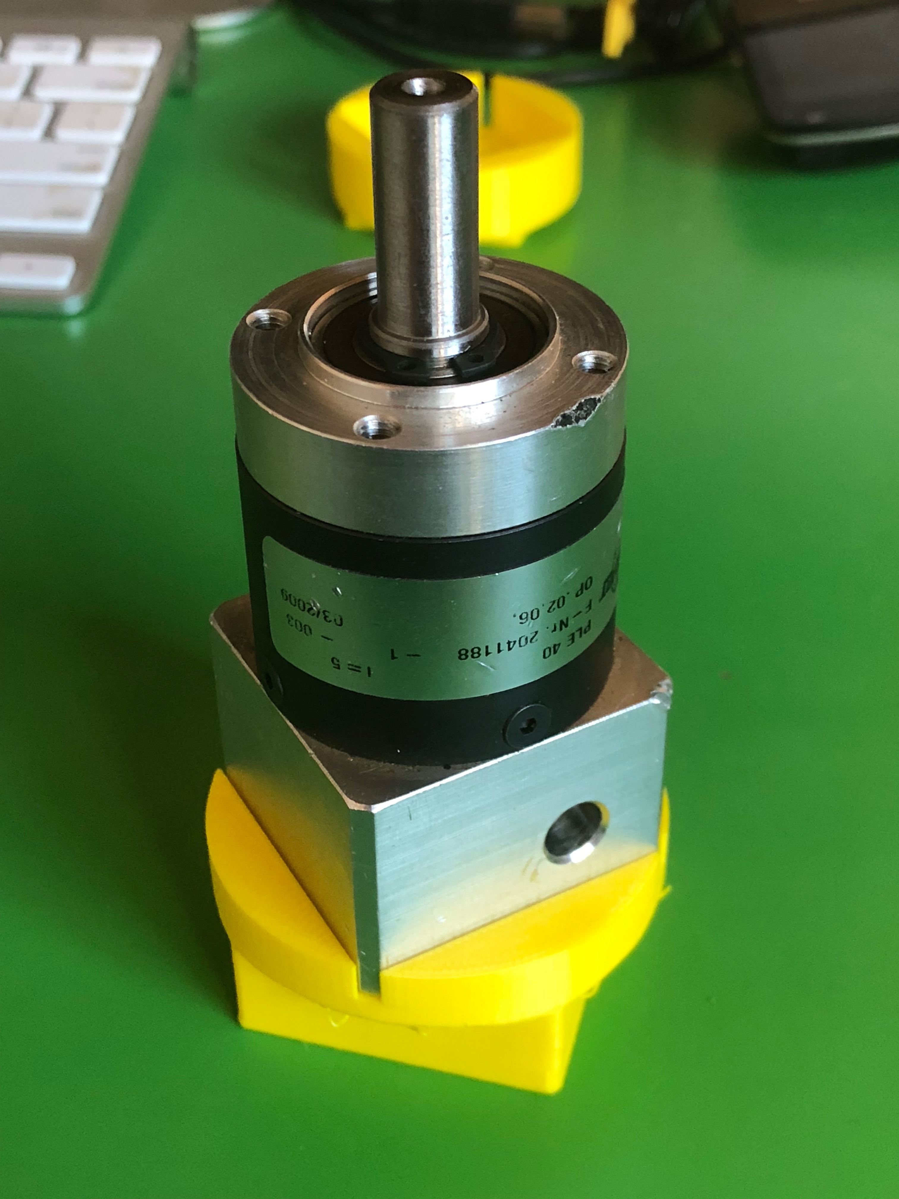
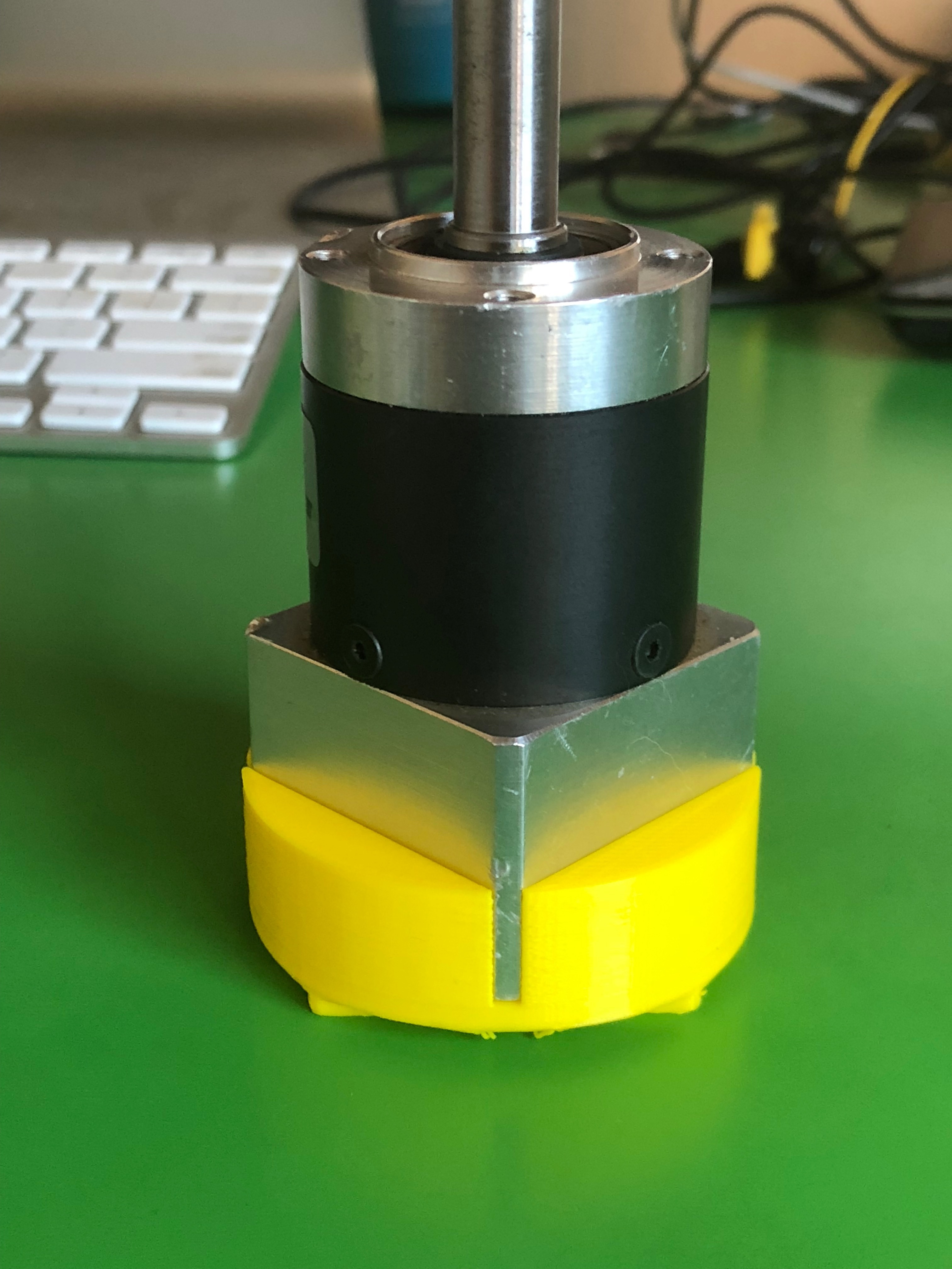
In my haste to get something going (as we’re now in summer here in Australia) I ordered a 2nd hand Neugart PLE40 5:1 on ebay, not noticing it had a larger square section over the coupler.
This meant the @pacificmeister Motor gear box mount doesn’t fit, as there’s too much distance between the SSS motor shaft and the coupler. So I’ve rejigged the Fusion 360 files to make it fit with the larger section. This gives the shaft about 10mm of length to attach onto the coupler which I’m hoping is enough.
I think I’m going to have to drill the 4 holes in the square gearbox mount to allow the M4 screws to go through the entire length… Otherwise, I can’t see there’s anyway to secure the gearbox AND the motor at the same time, unless it goes through to the seal mount cover to secure it.
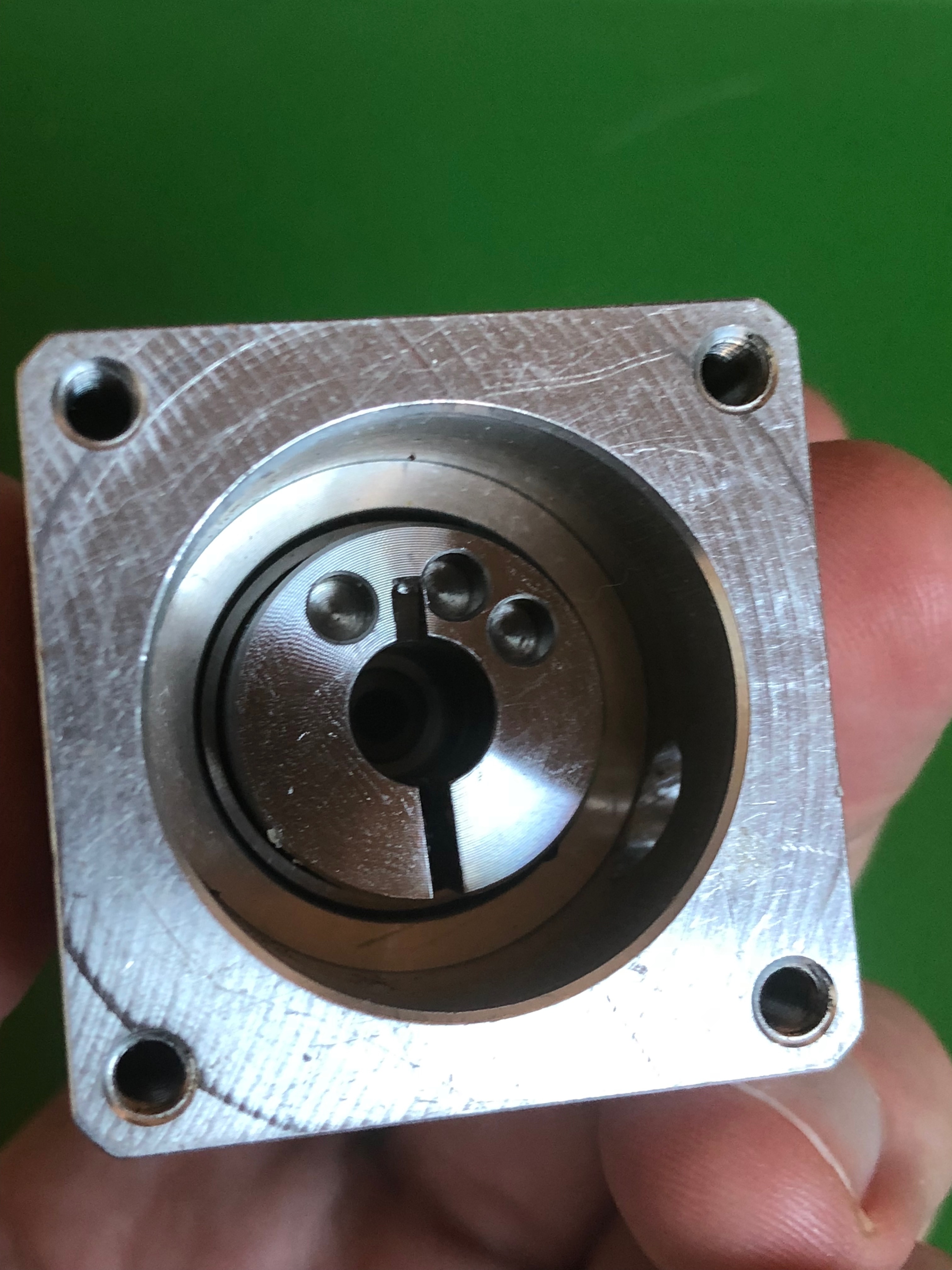
-from looking at the CAD, the only coupling between the notched drive shaft and the gear box coupler is through the use of the grub screw on the coupler? Is this is enough to hold even with the torque?
Hi @smarm, great to see your progress. Yes that grub screw is all it takes, I was worried too but so far there were no problems. Is your motor shaft long enough to fit all the way? Else maybe you can cut the aluminum block down. Good luck with your build!
Here are my two cents about couplers. I had a bit of history with them on my DIY CNC. Couplers need to be clamped on super tight. Hand tight is often not enough. You also need flexible couplers since its impossible to allign everything perfectly.
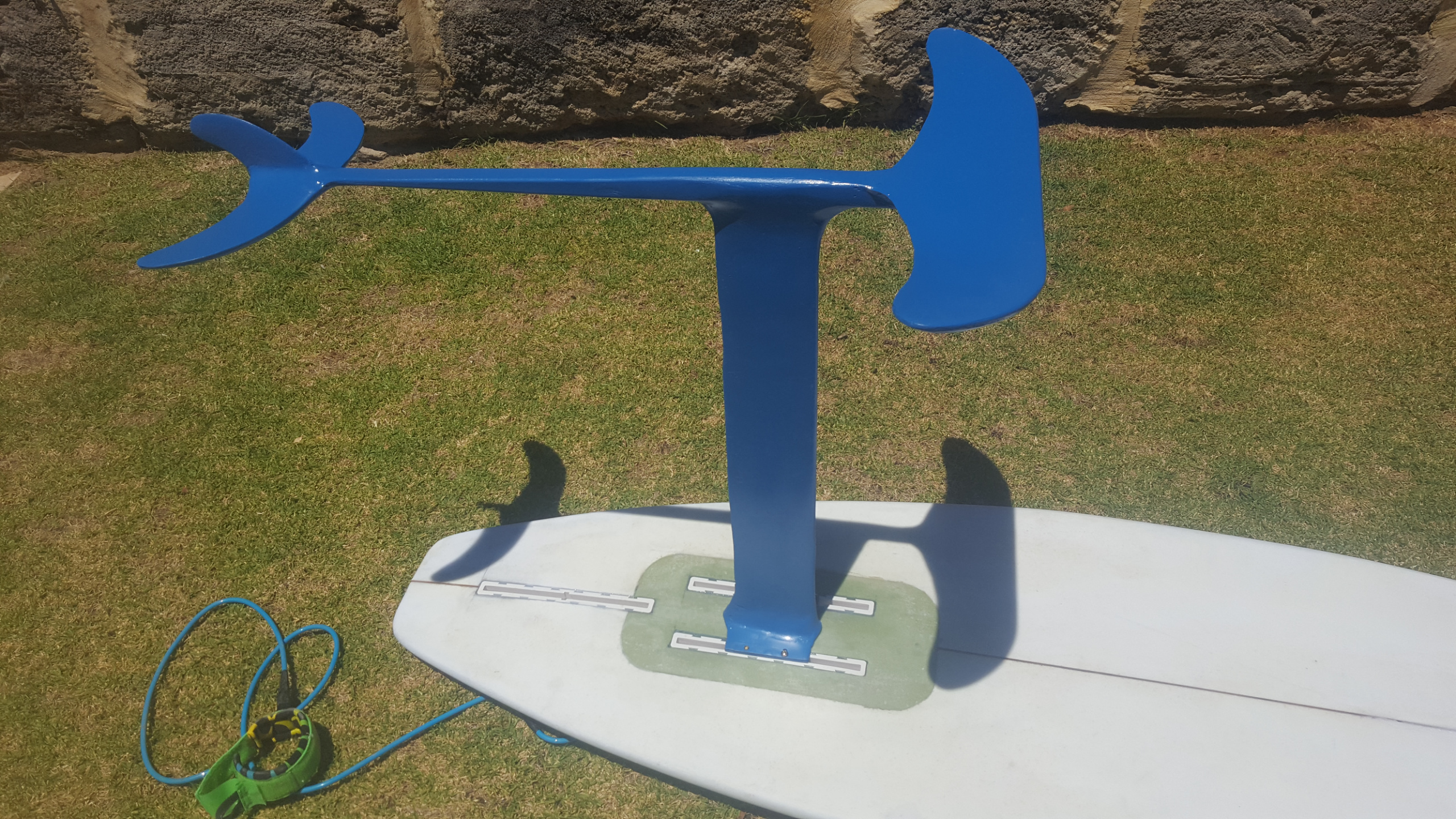
I’m also from Aus perth. Below is board and foil made from scratch. My next project will be an efoil so I’m keen to catch up with any other West Aussie’s that are working on building an efoil
Did you end up drilling the holes? Was it difficult to drill? Do you know what material that flange is made out of? I can’t tell from pictures if its SS or aluminum.
Let me know how it goes. I’m in the process of editing your motor gear box to mate with the seal mount by adding 4 more m4 bolt holes through your part between the current gear box mount holes. And then rotating the 4 gear box mount holes and nut holes on the seal mount by 45 degrees.
That should allow the extended gearbox flange to bolt directly to the motorgearbox mount, and then a long m4 bolt can be run from that motor gearbox mount all the way around the gearbox and into the seal mount.
Actually, just looking at that now and I don’t think it’s doing to work unfortunately. The round body of the gearbox meets the aluminium flange on this edge, and I don’t think you’re going to have enough room to fit the M4 nut.
I think the easiest thing will be to drill through and use the original recessed mount points.
I have made changes to your file and am planning to make the changes on the seal mount tonight.
The m4 nut sits in the cylinder body section of the seal mount, which is the same thickness around the gearbox no matter whether it is at the corner of the flange, or perpendicular to the center of a side on the flange.
Side note, which orientation are you printing the seal mount? thread side down or gearbox side down?
Also, we wouldn’t even need to use m4 bolt through that part of the mount. We could use m3 since it doesn’t go through the gearbox. That would result in a smaller nut on the sealmount side.
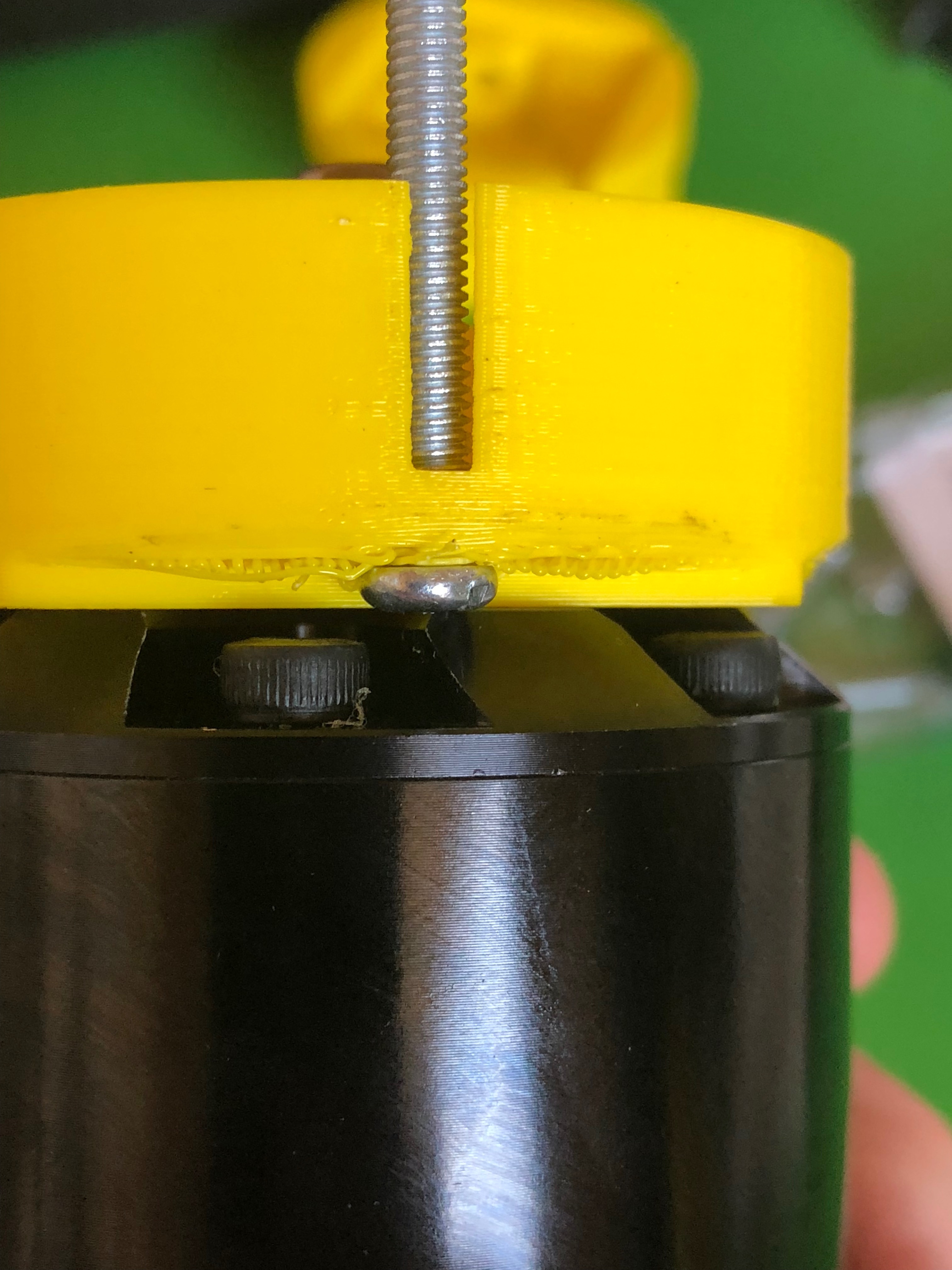
One thing that I’m noticing after printing your motorgearbox is that there is barely any room to screw on the nut which holds the gearbox on the mount… The original file allowed for ~1cm worth of room to spin the nut down. Your design has just about zero room for that…
Yep, you’re right it’s tight, but it still fits. It’s been compromised, as anything you add here, means the length of shaft meeting the coupler is reduced due to the extended aluminium flange.
I’m planning on cutting off the head of the bolt and use a nut at each end with some loctite to help with assembly.
Spent a bit of time wiring everything up electrically, getting ready to test fire the system whilst waiting for the lip seals to finish the propulsion unit side of things.
Took me quite a while to realise the Seaking 130A ESC doesn’t have a BEC… the manual doesn’t even tell you this.