Part 1 - When to select the right impeller (for jet propulsion) or the right propeller

(I have been researching and developing propellers for many years, so I can design propellers with very high efficiency for each speed mode and for each type of vessel)

In order to be able to select the correct propeller for the e-foil drive, you must first measure the torque of the drive prototype. Prior to measuring the torque, the drive prototype must be fully assembled - ie engine, gearbox, clutch, shaft, bearing, gasket and lubricant. You can measure the torque in several ways. youtube has a lot of inspirational videos. Simple design for torque measurement: https://www.youtube.com/watch?v=3pG90WreWyo31 (from 2:30). The video also shows what needs to be measured to calculate the torque

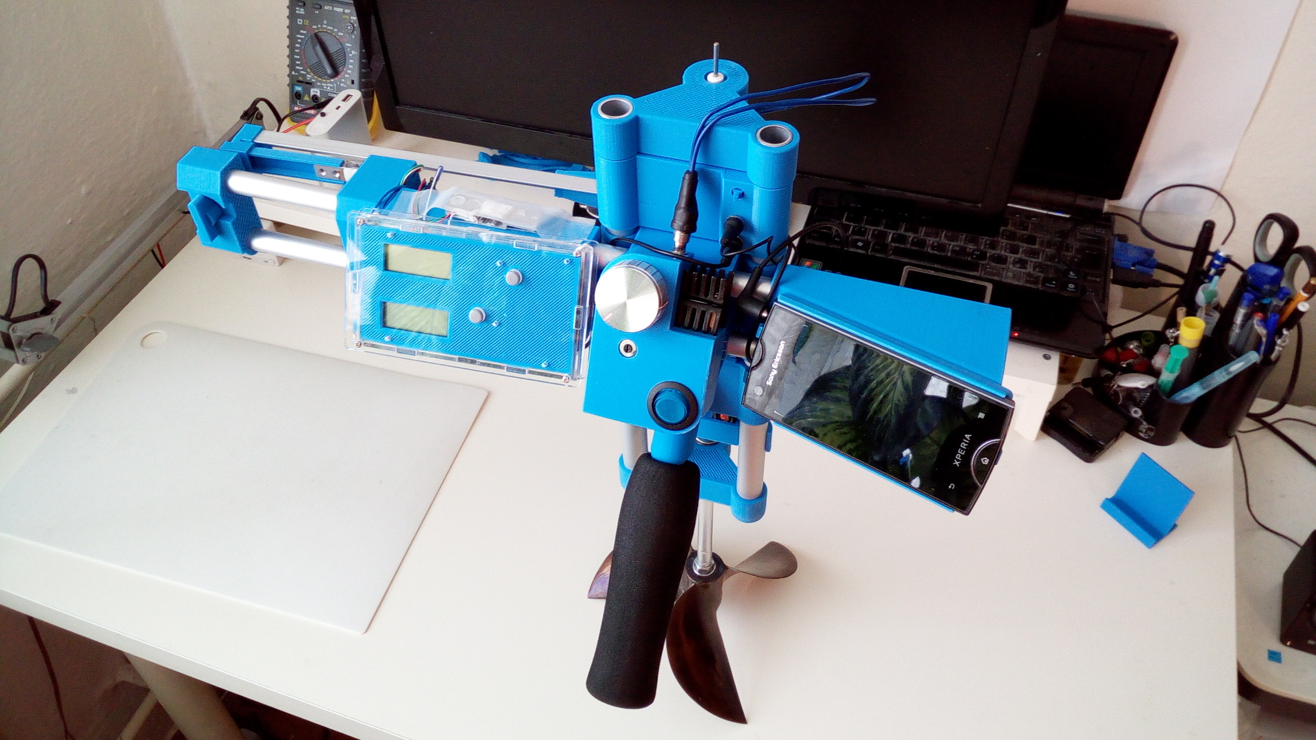
This is my torque meter

Torque measurement consists of the following three steps:

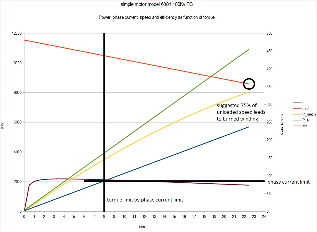
Step 1 - First determine the maximum engine RPM. The engine must be separate, nothing connected to it (transmission, clutch, sealing, etc.). The battery must be fully charged. The speed controller turns to the maximum and the RPM is measured with the speedometer. The RPM data is then permanently recorded.

Step 2 - All other parts of the drive - clutch, gearbox, shaft, bearing, gasket, lubricant, will be connected to the engine. This complete drive connects to the torque meter. The battery must be fully charged. The speed controller is rotated to the maximum. The drive shaft speed is decelerated mechanically by a brake, propeller, alternator, etc., so that the engine speed is only 75% compared to the measurement in step 1 (engine manufacturer or some literature recommends 70% RPM, etc.). The arm pressure (g) is then permanently recorded.

Step 3 - Finally, the torque (Nm) of the known formula is calculated from the arm (g) pressure, arm length (cm) and RPM. The calculated torque value is then recorded permanently.

All the data found in Step 1 to 3 are needed to find the right propeller. Without these data, it is almost impossible to find (buy, produce, design) the correct propeller for e-foil.

NOTICE
If anyone has an interesting question about torque measurement, I’d like to answer the question. But I will only give the answer here to this post! So I will not create new and new posts anymore, because the topic would become very confusing and would have a lot of unnecessary contributions.

2 Likes

For measuring the torque in a test setup, this mehtod of torque arm and kitchen scale is very easy. I have measured my motor with this method. But for underwater testing the long arm on the side would not be ideal. Thanks for sharong the link, is your own device more compact? Live measurement of propeller/impeller torque while riding would be really cool and useful.

That is a nice cleaver prop!

okely dokely! apologies for jumping the gun!

What are yout thoughts on the Torqeedo propellers? Torqeedo+Ersatzpropeller+Propeller+f%C3%BCr+Travel+1003+V9%2Fp790 online kaufen | eBay

They look similar to the one on your desk.

Please explain your test stand. Thank you!

4 Likes

WNT mate you need to take it down a level, this is a social friendly place for all of us to chat. yes it may get a bit jumbled at times but we can follow whats going on easily enough and not all of us are experts on making Impellers so please stop with the arrogance there is no need for it. You are making it unpleasant for everyone. I believe others will agree with me on that and no one agrees with you. Good day sir and back to the topic at hand.

6 Likes

I am following this forum as a still reader since it all started. Now I just registered to let you know that your way of communication is very arrogant. I have not red one comment that proves that you now what you are talking about. Can you not just design a drive system and show the, in your opinion, best way? Sorry if that sounds rude but I am really annoyed, and I guess some others are as well…

6 Likes

Step 1 - easily done with VESC and data logging with BLDC-Tool.
Step 2 - 75% of no load RPM with unlimited phase current will overload my motor and ESC by factor greater than 2.5 .


A better method would be to measure the RPM and torque while applying the maximum allowed phase current. As i have no gearbox, i do not need to consider it. So the torque can be calculated from the Kv, it is maximum allowed phase current/(100RPM2pi/60), if i use 85A, i can expect ~8Nm.

Step 3 - absolutely unclear to me. How shall we proceed when the data is available?

1 Like

You can never rely on BLDC engine data, in all cases are inaccurate - eg video https://www.youtube.com/watch?v=IP4PFq6u7wg from 6:45

E-foil is a very complex kind of technique (more complex than the F1 body), so prototype production requires a careful procedure. Any minor error (wing, drive, impeller, nozzle) can significantly reduce the parameters.

Therefore, it is very necessary to first measure and then calculate.

Therefore i measured the Kv at no load. So if i have this data, what comes next? So far you told us, you have a superior way to choose the prop, but there is no content from your side so far. We would like to understand your method, but so far you only told us, what we could have done wrong in the measurement of the motor constants (although this is not the problem).

2 Likes

Well, this is not BLDC data, it is just crappy measurement. He has a SD of about 3k RPM while driving anything from 5k - 11k RPM. I bet I could do more accurate measurements by judging the sound with my ears. This video only shows how not to measure RPM! The BLDC-Tool gives you exact ERPM and with encoder you get ~ 0.2 degree precision (2000steps per revolution). I doubt you have anything nearly precise.

Is the data beyond 85A phase current extrapolated or did you really drive your motor with ~240A phase current?

This is just model based data, as the naming of the graph stated. I measured R(50mOhm), Kv(100RPM/V), no load current (1.8A).
The equations used are:
I=Torque/Kv+no load current
speed[rad/s]=(46V-(I*R))*Kv
P_mech=speed * Torque
P_el=U * I
eta=P_mech / P_el
using SI units.
This simple model is used widely to get an estimation what goes on and is valid for permanent magnet motor (asynchron motor or series motor are totally different). As i wrote: 80-90A is my phase current limit, which can be easily programmed using the VESC.
At least its enough to tell, that you will burn up your motor when braking it down to 75% of the no load speed while maintaining full voltage. The torque value you would get from this measurement will always be way too high. You need to measure with the maximum phase current which your motor can take for a longer time, lets say 5 minutes. But WNT maybe has an other opinion about this or uses other electrical machine type than we do?
So WNT, what shall we measure, at which point will it make most sense?

1 Like

Ok, I see, it is the standard motor model.

Normally you design motors for a point around max efficiency, more likely on the side of lower RPM of the peak than the higher (because of the rising power). So I guess your 8Nm is a pretty good point.

If you go above the current limit the ESC will just reduce the duty cycle (internally) and your output power will get less. So designing for a point above the phase current limit will be inefficient (from motor and ESC side, maybe it has advantages in prop designing, I don’t know).

WNT, appreciate your insights!

Does any information exist regarding prop load distribution?

We would like to perform FEA and suspect the load would not be evenly distributed over the blade surface?