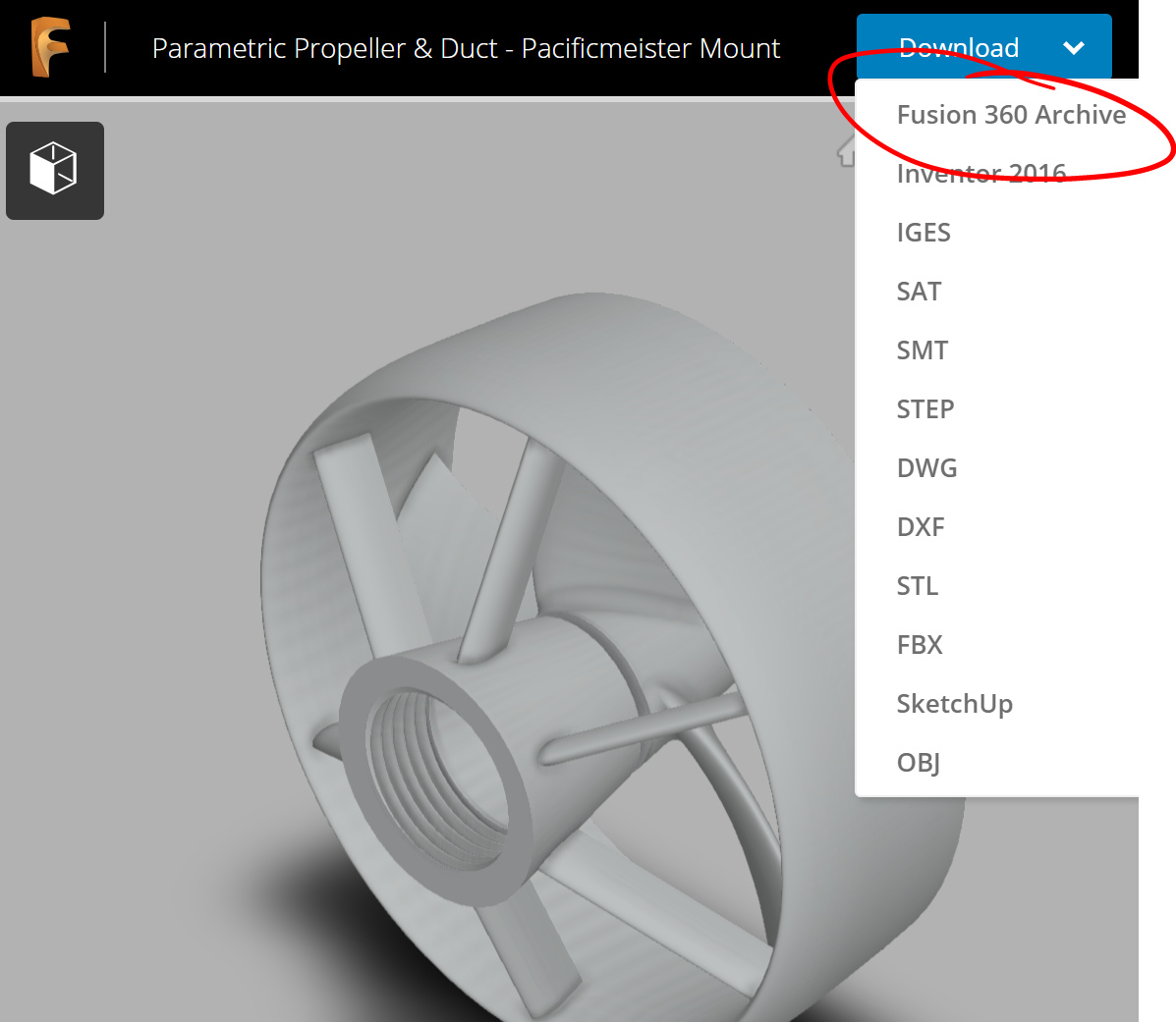
Hi @Fabien_n, Rev3 references the parametric prop/duct linked in this thread above (I think). Here is again the direct Fusion link to this parametric prop/duct component: Fusion. Download the Fusion 360 Archive here:
I would like to thank everyone for a great design in Fusion 360. I am new to the group. Is is possible to create a motor that works in opposite rotation from this design? I would like to make 2 smaller motors the rotate like they would for say a quad copter. Thanks for any help. This in itself is a great piece of design work.
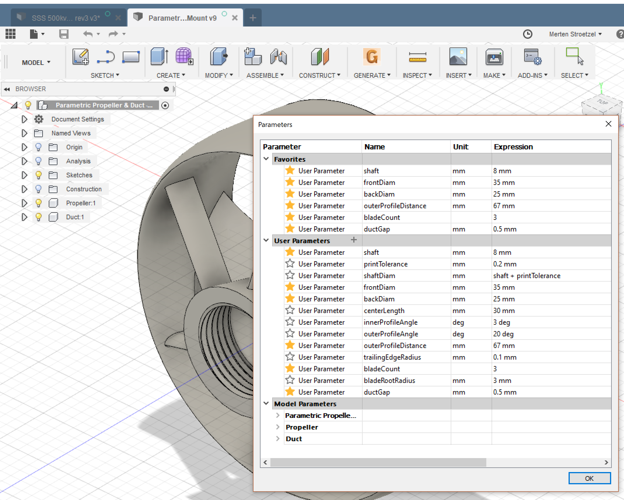
I seem to be having issues with this breaking when outer diameter and other values are changed. Some error to do with references. Just trying to track down why, but perhaps some changes in Fusion360 were implemented since this was made. Is this currently working for others? If not, @Taylor would have time to have a quick look? This is an awesome asset!
My mistake guys. Seems to be okay now. Trying to see if I can make this work with a larger 65150 build but things need to be scaled up a fair bit. Unfortunately I’d have to scale up the base profiles and there’s no nice way to do that with tangent handles. So I’ll play around with that by eye and see what happens.
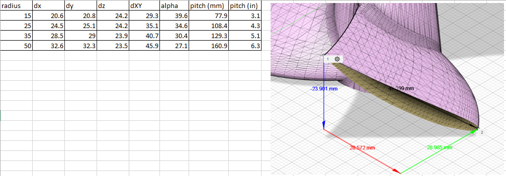
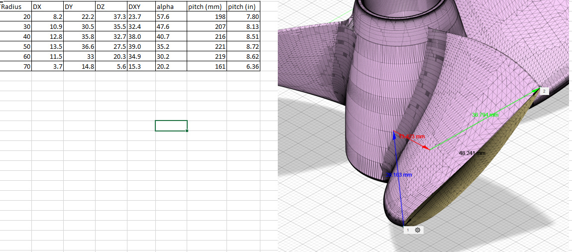
The @MaB prop is better, but still not perfect. As you can see it is pretty close to 8" pitch, however there is a +/- 10% variation in pitch along the radius of the blade, so it maybe possible to improve the efficiency of the prop?
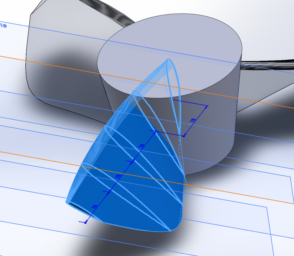
My idea is that you can define several airfoil sections at different radii along the blade of the prop and loft the blade through each airfoil section, thus getting more precise control of the shape of the blade.
Hi Mickey,
nice to see someone looking closer to the propeller shapes. I did some preparations to do a excel folder (VBA) to achieve parametric propeller design along the lines given by the definitions of the International Towing Tank Conference. I think you should define the blade sections along the respective imaginary cylinder shell - not along a straight cut. (see link below, page 53 ff) https://ittc.info/media/7939/2017-ittc-dictionary.pdf
Another remark: it is not sure, that a constant pich propeller is the best solution in all circumstances. Propellers for boats and ships have often a different pitch near the root and the tip of the blades.
I had another idea in mind. Don’t know if it is valid. I was thinking that, independently of the pitch, constant Reynolds number from leading edge to trailing edge of airfoil section was important too. This would lead to chords decreasing toward the tips.
On most propellers chords of blade sections do decrease towards the tips. But the main reason is reducing the tip vortex. On ducted props there is no need to do this because the small gap between duct an tip oppresses most of the vortices (Kaplan propeller).
Hi Heimfriend, the nomenclature I used is probably not to best and can lead to confusion so I’ll clarify what I mean:
Blade pitch (pitch angle) - the angle a certain chord section is relative to the plane of the disc of the propeller, this should decrease radially given the blade travels faster at the tip than the root
Propeller pitch (geometric pitch) - the distance the propeller would travel forward in one rotation in an idealised medium. (ie a common prop size is 7x8" which means 7" diameter and 8" propeller pitch) My assumption is that this should be constant for any section of the blade
So to your comment - I agree that blade pitch should not be constant. But are you saying that the propeller pitch should not be constant under some circumstances?
Note there is also the constant pitch prop versus the variable pitch prop. The variable pitch prop refers to a different type of propeller where the blades of the prop are rotated to adjust the propeller pitch to suit the forward speed of the craft.
According to ITTC (and naval architecture textbooks) the props with blades which can be rotated (along the blade axis) are called “adjustable pitch props”, the “variable pitch prop” has fixed blades but a slightly different pitch (I don’t talk about pitch angle) toward blade roots and blade tips, e.g. to avoid cavitation. May be the small differences you found calculating @MaB 's prop are exactly that. The idea of constant pitch is connected to a linear flowing water stream surrounding the propeller with uniform velocity. Because of water viscosity and friction along the hub, shaft or motor this is in reality not the case. The water stream near the hub is slower (before propeller entry), compared with the surrounding stream.
The prop pitch is just an kind of mean pitch, usually measured at 70 % of the blade diameter.