Hey Manu, does this version of mast clamp you posted fit on gong mast or does it need modification?
hi @Nace_Erznoznik no it is not the design for the gong allvator mast. I have the stl I have to put it online.
@Manu Can i kindly ask you for stl file please? You would save me few hours of using fusion programm. thank you
@Nace_Erznoznik no problem but it will not be possible before 26/10 because I’m not home … work requires
I have the following questions about the PM build as I am about to seal up my drive-pod:
-
Are both ends of the drive-pod GLUED shut? MastcClampBack to metal tube on one end and the SealMount on the other end? Back makes sense but on the SealMount there are two o-rings. Is this just for extra safety in addition to the glue?
-
Are you using the two-part epoxy for this gluing process?
-
If you need to re-open the drive-pod after it is glued shut how do you do it?
Thank you in advance for your help!
Thank you Manu;) I will warm my 3d printer;)
on the @pacificmeister model only the mast clamp is glued to the epoxy, the seal mount is sleeved and fixed with small screws all sealed thanks to the two joints… post 427…
for the model of @Yinnon_Haviv the mast clamp and the seal mount are not glued and are sealed thanks to the joints and maintained by small screws.
2 Likes
Wasn’t sure if you were kidding or serious so want to confirm. Are you saying you fill grease in both areas #1 and #2? I know it goes in area #1. Thank you!

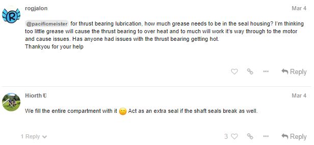
Yes we filld the entire compartmemt on those drive uinits. But i dont know if it realy works well.
1 Like
Manu I am writting just to remind you, if you can send me the mast clamp. Thank you very much
1 Like
The link of the STL for the GONG Allvator Mast Clamp
https://www.thingiverse.com/carvalhoemmanuel/designs
3 Likes
Manu thank you very much😀
1 Like

Hi,
Thanks for providing so much information about your project.
The only thing missing here is a Electric Diagram will all the components that you have used and the way you have connected it. Could you provide such diagram?
Best Regards,
João Rebelo
What value shunt have you used inline to your batteries
It’s a 100A/75mV shunt that came with the amp/volt meter: Amazon.com. I added it to my material list.
1 Like
Just to let you known , apparently @Gobbla used this kind of thing with shunt and it was off by x1.6 , prefer a hall effect one with adjustage screw and double Check the value with this:
https://www.amazon.fr/UNI-T-UT210E-mètres-Testeur-Capacitance/dp/B00O1Q2HOQ/ref=asc_df_B00O1Q2HOQ/?tag=googshopfr-21&linkCode=df0&hvadid=51038388126&hvpos=1o5&hvnetw=g&hvrand=14374052407015617376&hvpone=&hvptwo=&hvqmt=&hvdev=m&hvdvcmdl=&hvlocint=&hvlocphy=1006094&hvtargid=pla-276332453915&psc=1
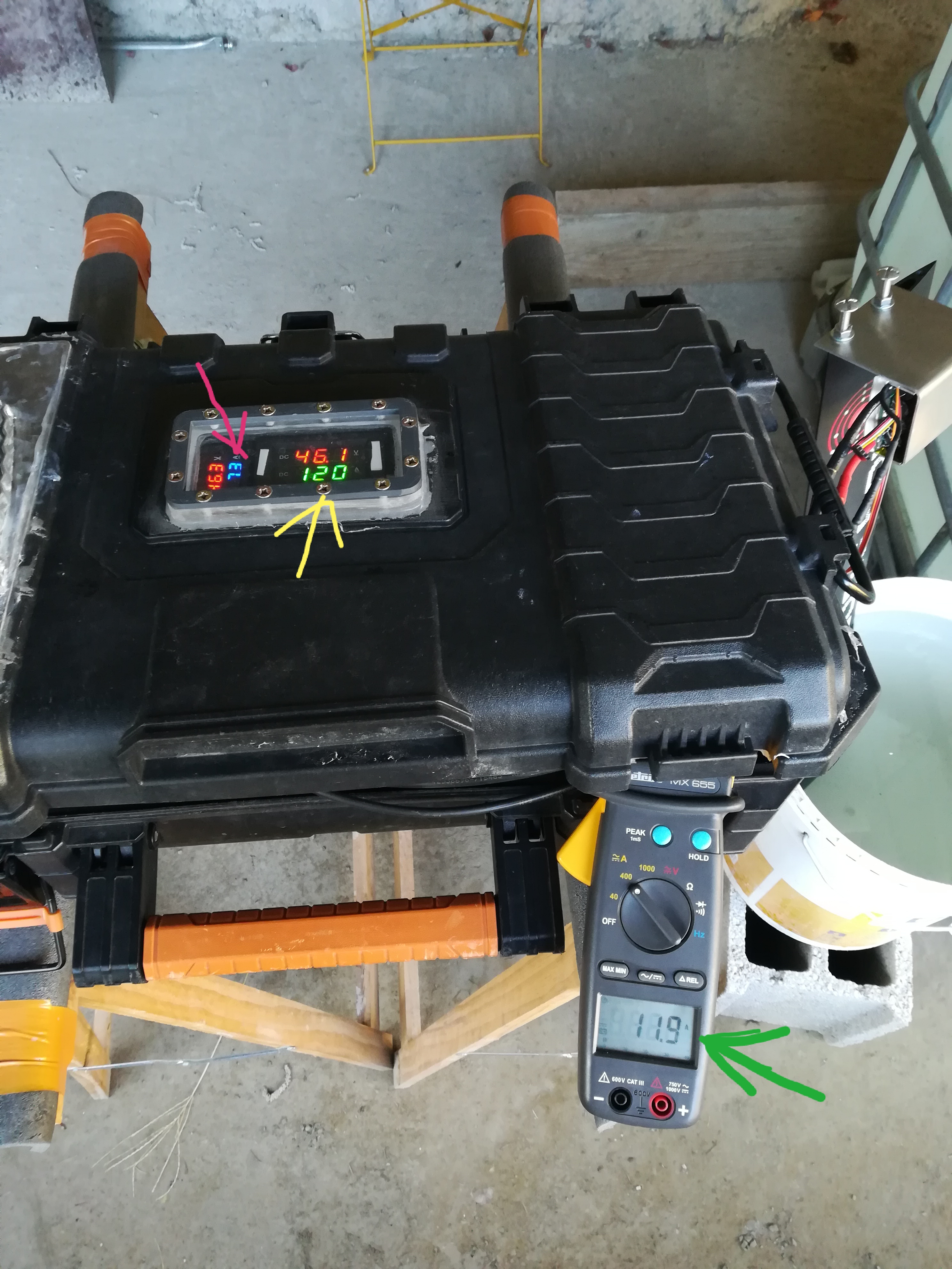
Pink arrow : measure with shunt
Yellow arrow : measure with hall sensor
Green arrow : Mesure with metrix mx 655
1 Like
@Yinnon_Haviv did you get any further with testing your PG gland cable entry into the mast clamp? I’m keen to do similar and hear your result.