Hi Guys! Needless to say this forum rocks! I have been working on an oil cooled direct drive build for the last few months. Since cooling these motors seems to be the limiting factor and failure mode for an overloaded motor the thinking was that I would be able to run a much smaller motor at a significantly higher power by running it submerged in dielectric oil. This would provide excellent heat transfer directly from the surface of the motor windings and conduct that heat out to an aluminum housing with a large surface area. The rotation of the motor would cause oil to circulate providing epic heat transfer and great lubrication for bearings and shaft seals.
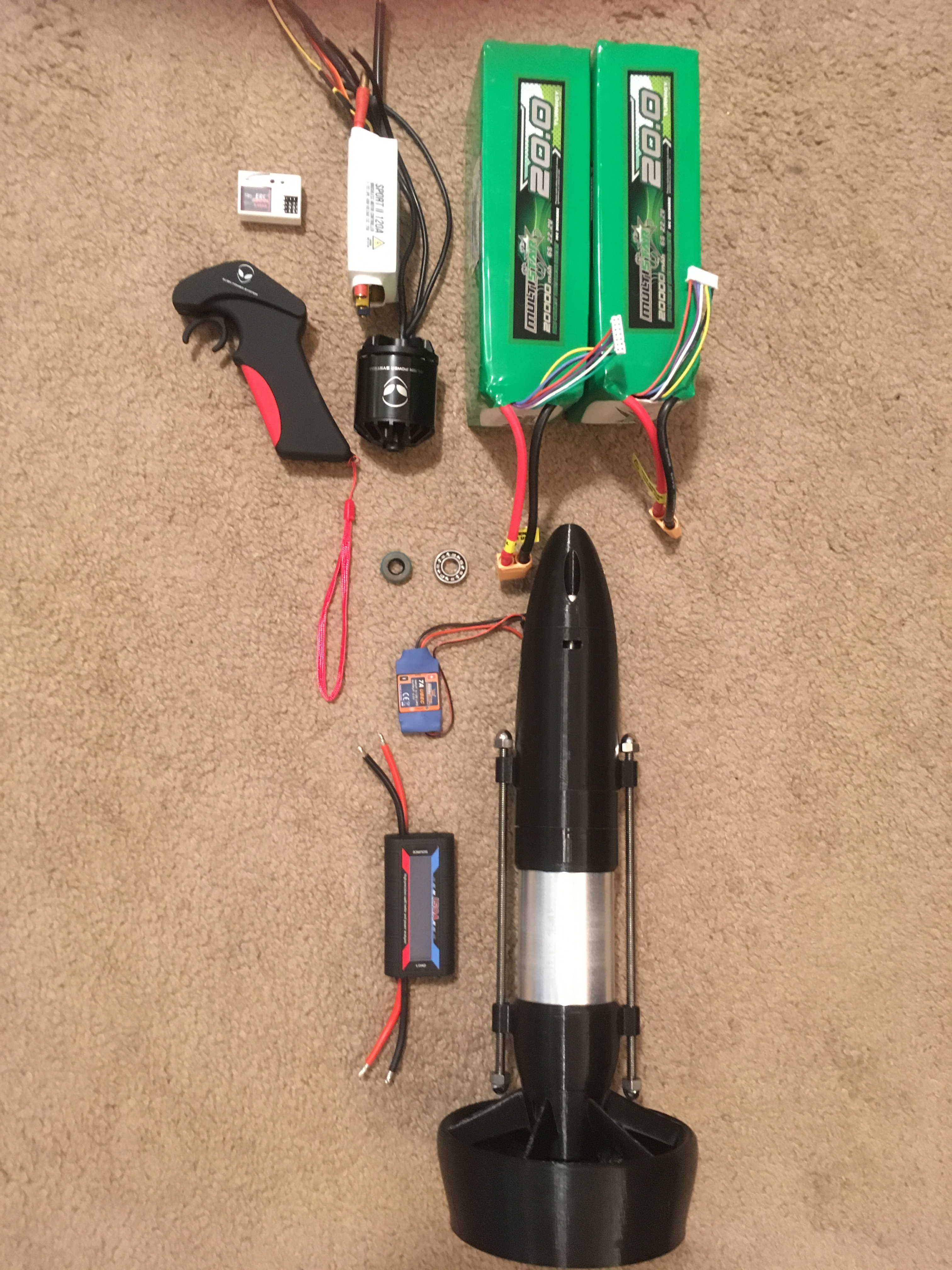
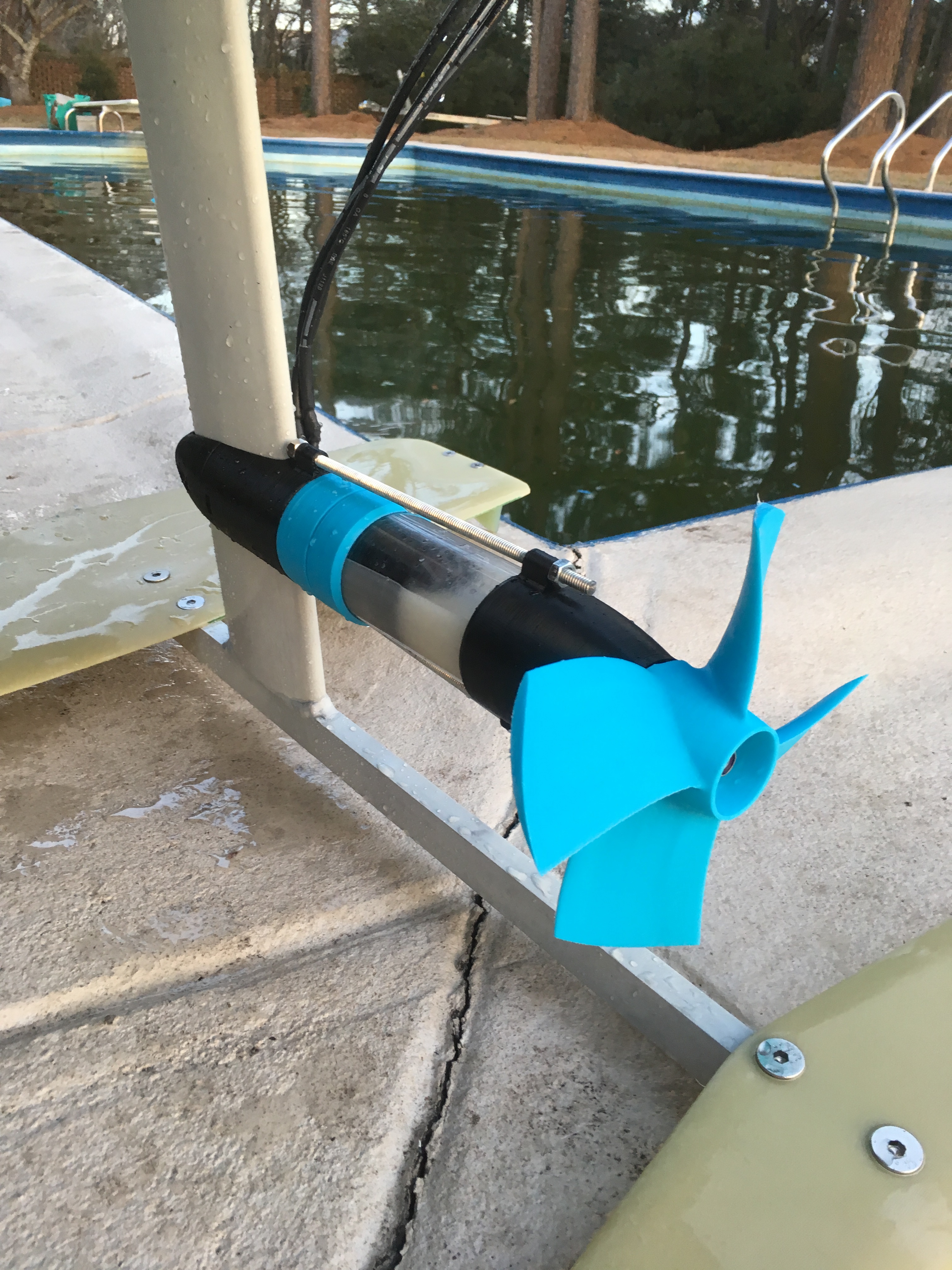
Here’s the hardware I am starting out with:
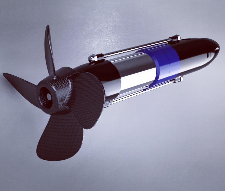
-Alien Power Systems 5065 90KV brushless outrunner (small I know, read on)
-Alien 150A speed controller
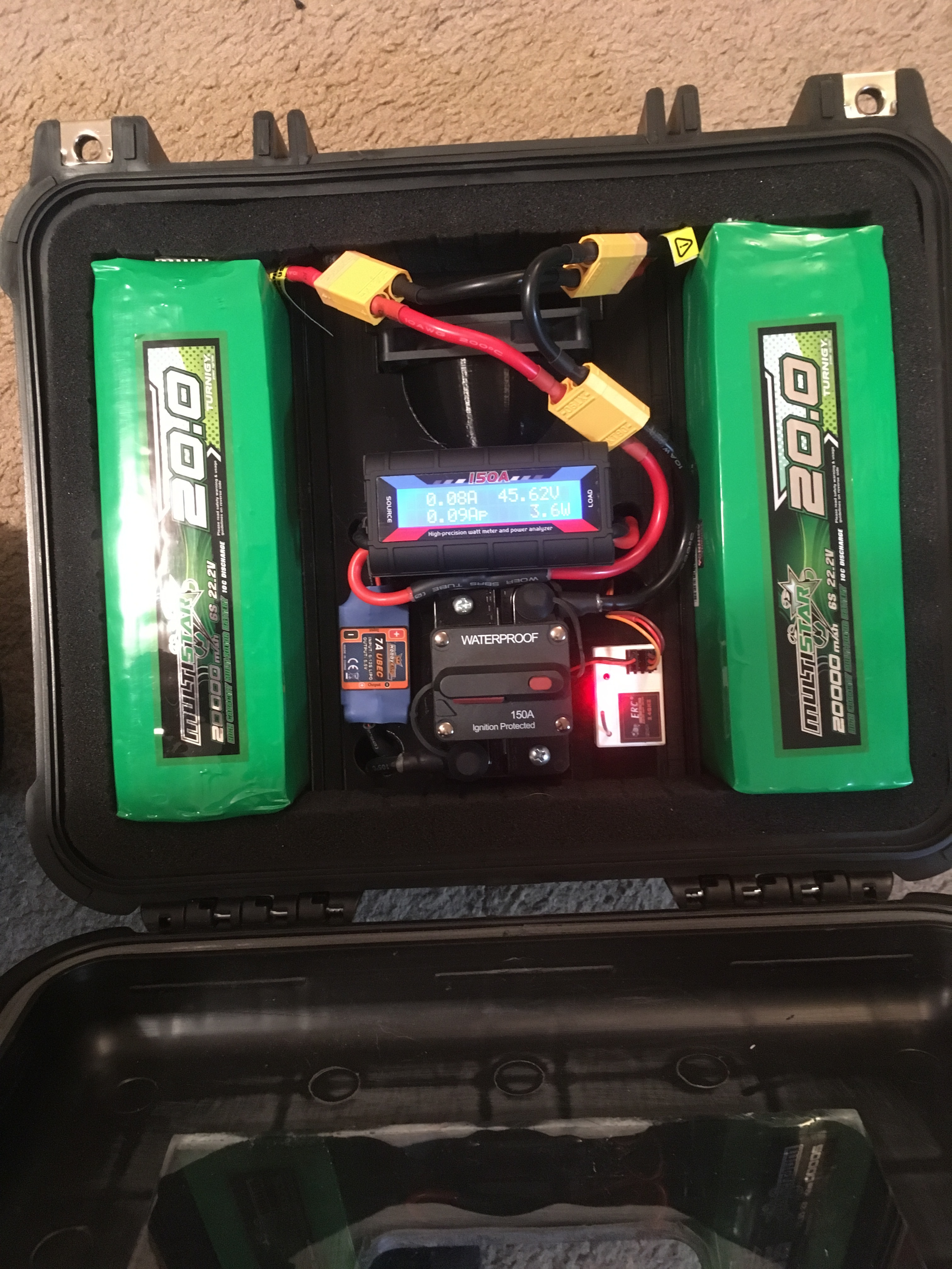
-2x turnigy 20,000mah 6s batteries in series
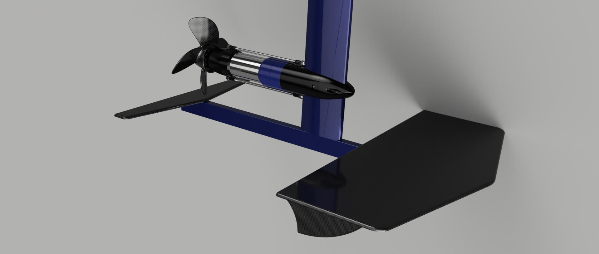
ebay “magic carpet” foil (cheap but I wouldnt reccomend it)
beater foam board that will be replaced once I know I can make the thruster work
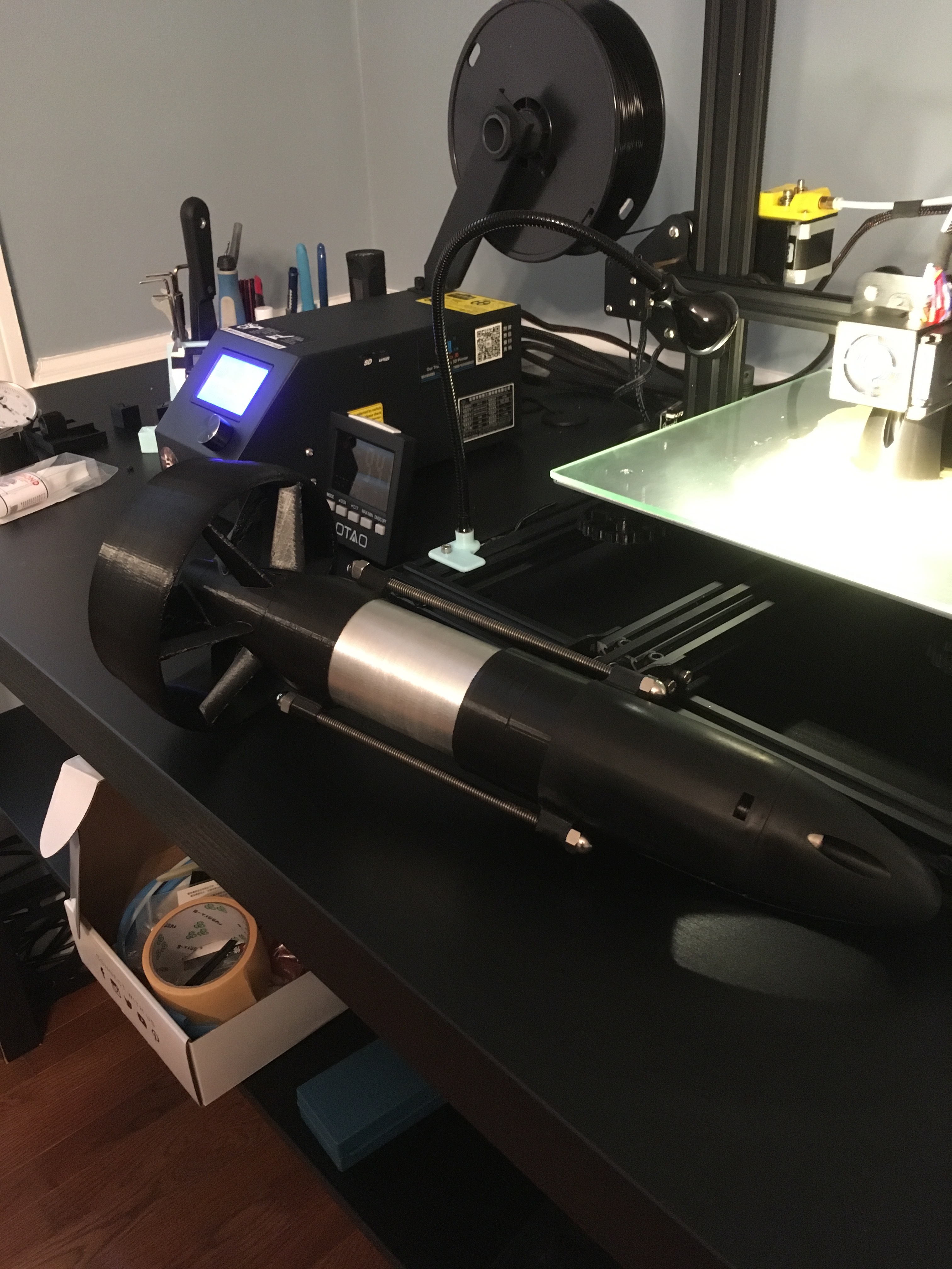
All the plastic stuff is currently printed in PLA and PLA+ using a Creality CR-10
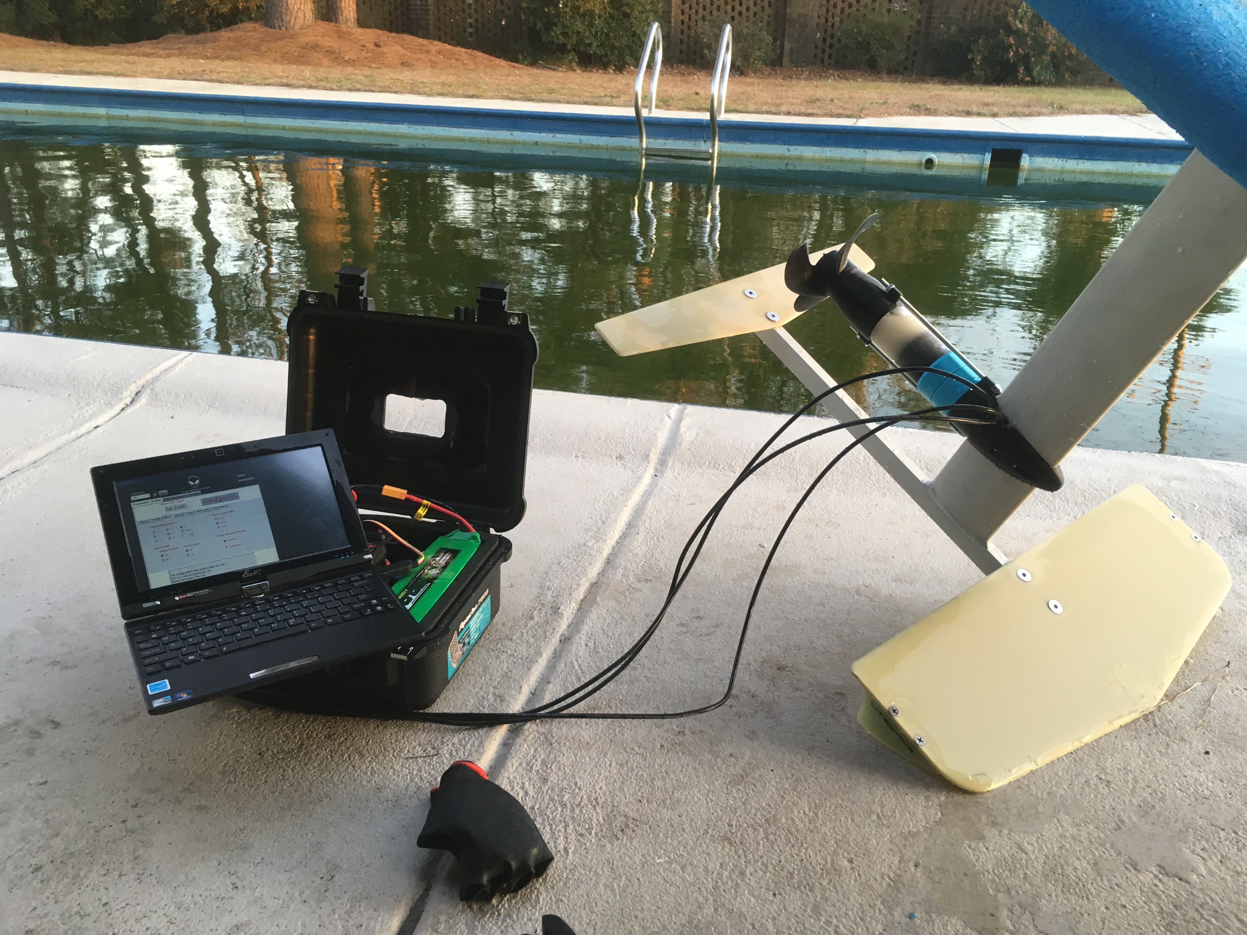
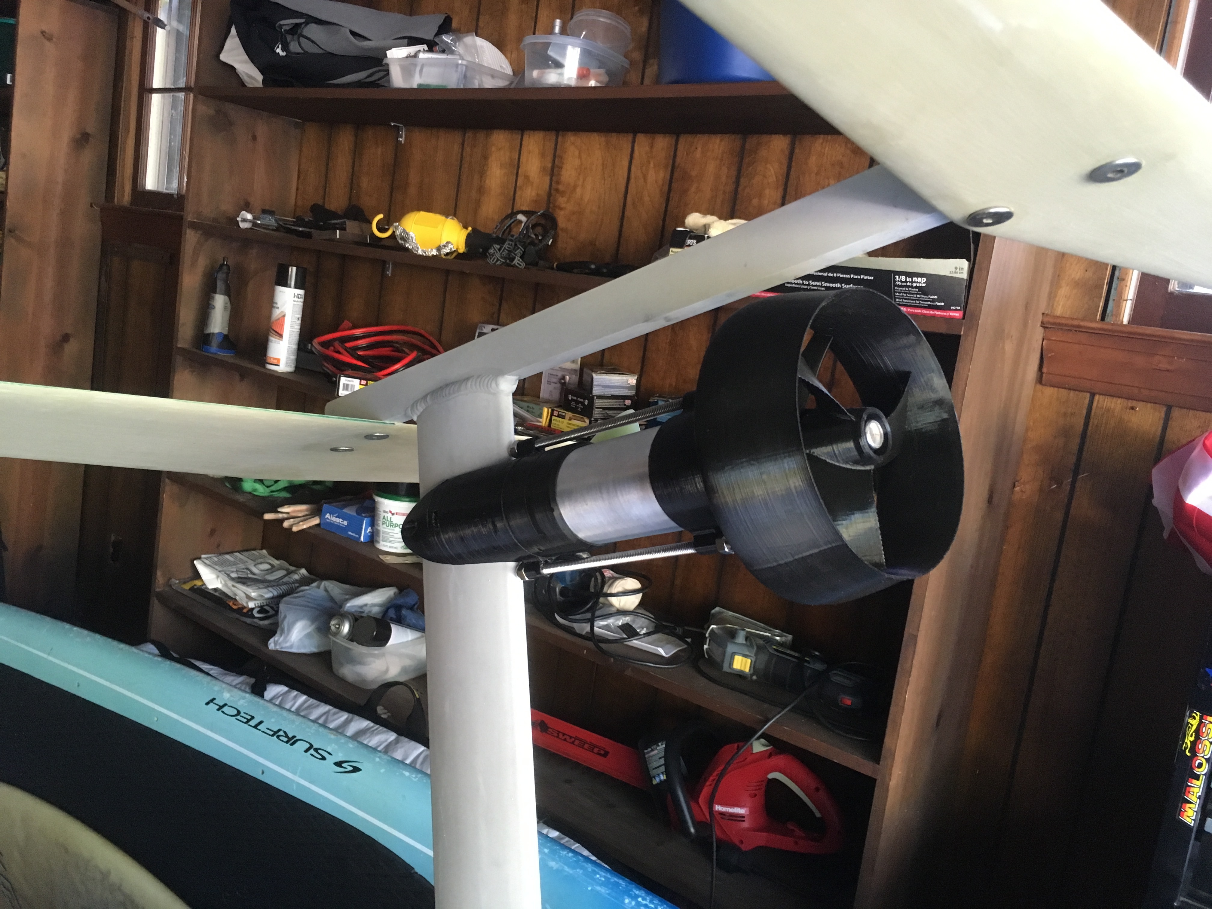
So here’s where I am at. I was planning to start off with a small prop and work my way up to a larger and larger prop until the motor was loaded up to around 3500W-4000W. I was under the impression that I could just keep increasing the load on the motor until I either had enough power to ride, or the just motor burnt up. However, after trying 4 different props and don’t seem to be getting the power I need and cant get the motor to draw more than about 2000W.
I started by printing off the 3 blade version of the parametric prop and the duct that pacificmeister posted. It only drew about 1300 Watts and the board would move through my pool (without a rider) at maybe 4-5 mph. Need more power!
I then Printed off a 4 blade version of that prop. It only drew about 1600W and would move just a bit faster. Still need more power.
Next I bolted up a solas prop for a 4-6hp outboard engine thinking if this doesnt pull some current I dont know what will. That prop pulled just under 2000W and would just get the board up on the foil (without a rider). Maybe 8mph.
Now I am starting to second guess my theory about being able to just load up the motor with bigger and bigger props until it either works or goes up in smoke. So as a last ditch effort to pull some serious current through the motor i printed off a four blade, 8inch diameter version of pacificmeisters prop. I rev up the motor out of the water then confidently drop the board into my green ass, freezing cold pool expecting to see big numbers on the power meter. I hit the throttle and the motor just shutters for a few seconds and then shuts off. I guess the ESC is sensing that the motor isnt rotating like it should be and cuts off. If I release the throttle and then reapply it. It shutters again for a few seconds then turns off yet again. If I give it just a tiny bit of throttle the prop turns fine but I think the big prop just requires more torque than the motor is capable of producing.
I am confused at why I wasnt able to pull more current with the same props that Pacificmeister is using. The motor must not be turning at high enough rpm right? at 12s and 90kv it should be spinning at just under 4000rpm (no load). Maybe it is hitting it’s max rpm before the prop is spinning fast enough to generate a significant load on the motor? What prop RPM is the @pacificmeister setup turning? I know I am really pushing my luck running such a small motor but I would at least like to load that motor to failure before giving in and buying something bigger. Any thoughts?
Very nice set up! The electronics compartment looks very tidy. What current meter are you using? And are you using the circuit breaker on the negative wire?
Regarding the limited power, does the ESC have some kind of current limiting maybe?
First of all, very nice setup! Small and clean tube and very good CAD model.
I guess the windings resistance of such a tiny motor with low kv (many windings of small diameter) is just to high to get more amps pushed through. So to pull more amps you should either get higher voltage (which might not work because of the ESC) or get a motor with less windings and same diameter (you might not want that due to more kv) or a bigger motor with thicker windings (and bigger diameter or longer).
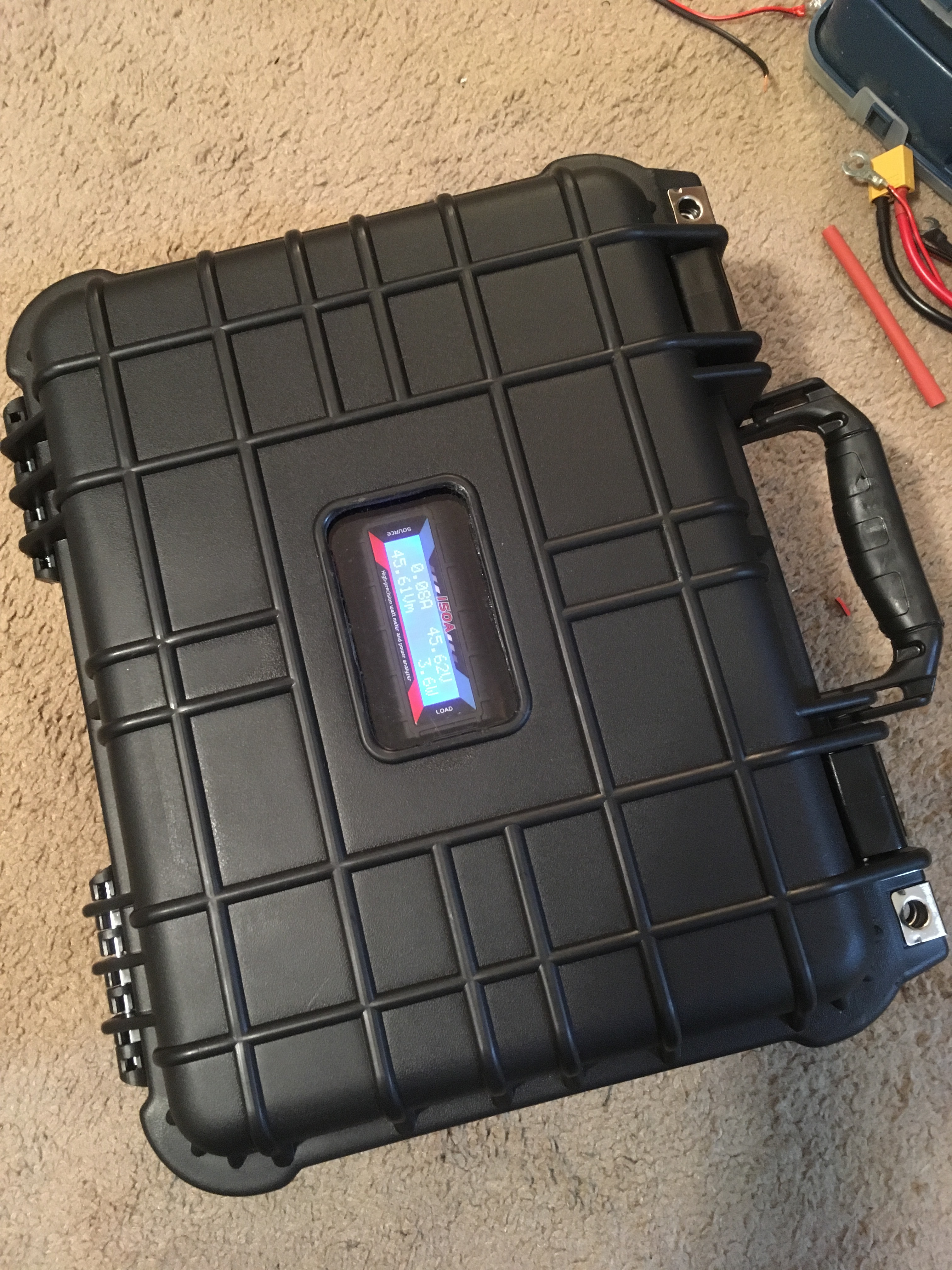
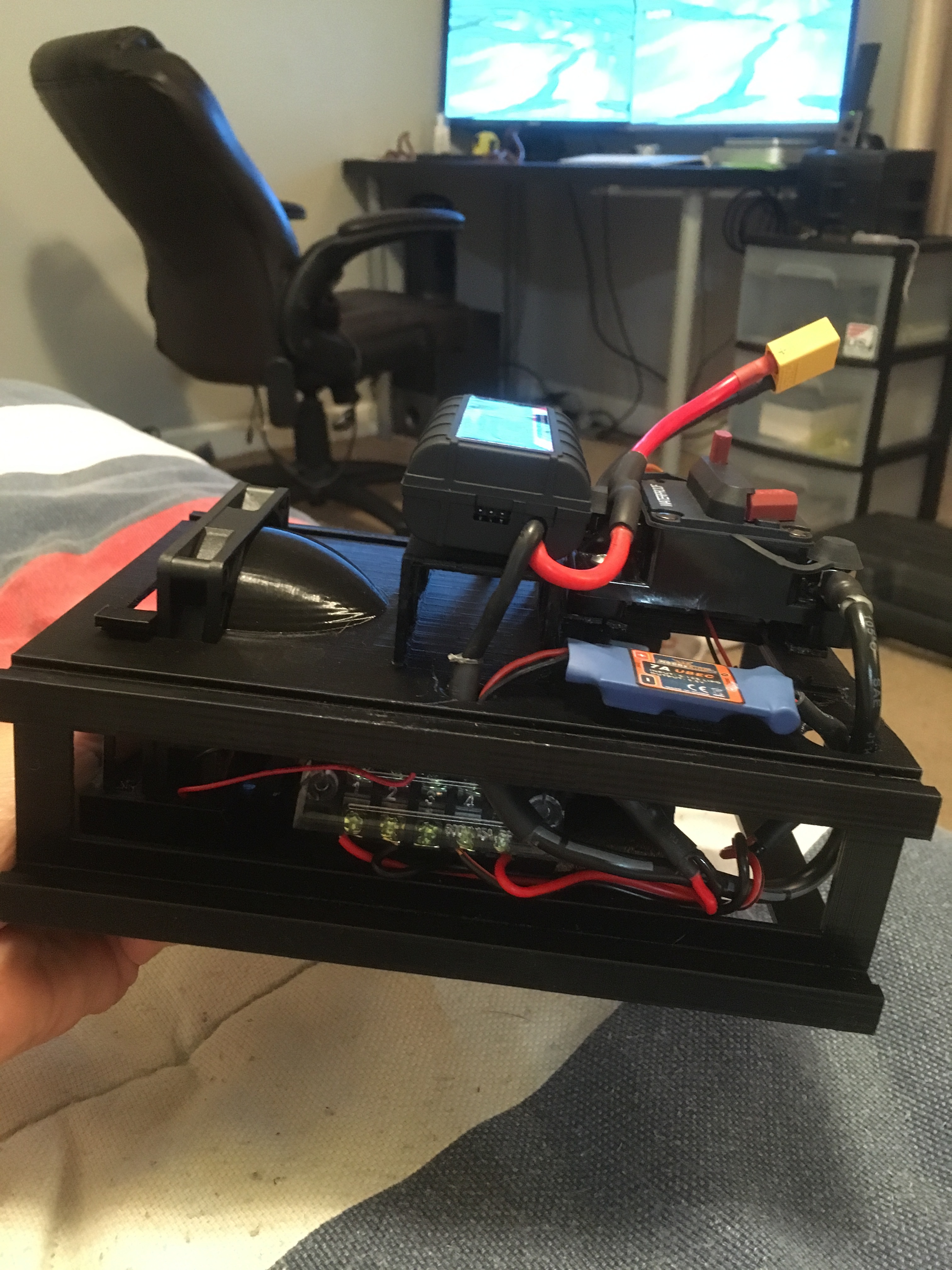
Thanks! I printed a rack to keep all the electronics organized and to hold the batteries in place. I have never removed so much support material from a print in my life! FYI: Harbor freight tools has those waterproof boxes for like 30 bucks!
The power meter is just the one off of the alien power systems website.
I do have the breaker on the negative wire. Do you think this will be an issue?
The esc is rated for 150A so I shouldn’t be getting near any kind of max power limit only drawing 2000W. I think there is some relationship to motor rpm and current draw that the esc is able to sense.
I would also look at your max RPM and current in unloaded state inside aluminum(?) shell versus no shell. If gap between the shell and rotor bell is small enough, your rpm will be limited by braking force of recirculating current in the shell, caused by rotating magnetic field of the rotor bell (more rpm=more braking force) and your prop will not even have any chance to get the rpm where it is loaded. In such a case most of your power is converted to heat instead of usable work, on already underpowered motor.
P.S. If your shell is non conductive material, just ignore this post.
I would not rule out that your ESC might limit the current. The rated current for a ESC is technically the motor current, not the current from the battery. If the motor is loaded down (high torque load / big prop), the motor current is much higher than the battery current.
I have done some testing with my BLDC in a lathe. This way I can simulate an arbitary torque load at almost any rpm. Using the VESC I mapped out various load points with a 50V power supply. The motor current at low rpm and high torque is limited by the ESC (a factor of 5 between battery and motor current is common in this scenario.). I did this to test my ESC cooling method.
There might be other reasons, too. I just want to give this hint.
I am pretty sure the rated current for a motor (1800W in this case) is just a suggested limit. Ie: the motor is able to draw higher current than its rating if the load (prop) is high enough but it will just start to burn up.
Heres the way I understand it. You should be able to bolt the base of the motor to something fixed and have it running at wide open throttle. With no load the motor should be drawing pretty minimal current. Now say that somehow you are able to grab onto the motor shaft and slowly keep increasing the load on the motor. As you do this it will begin to draw more and more current until eventually you exceed the rated current. At that point, the motor begins to generate excessive heat until the windings finally start to melt and short out.
This is exactly what I was hoping to do by running larger and larger props until I either had enough power to ride or the motor had a melt down. But there is a bottleneck somewhere and something is keeping me from being able to run much more than 2000W. Any ideas what this could be?
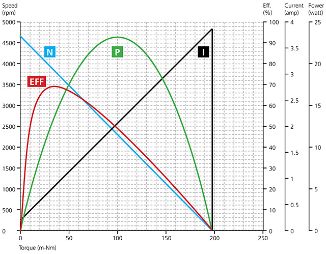
Does anyone know how load affects the max rpm of a brushless motor? I know with a standard brushed dc motor with a commutator, rpm is controlled by simply throttling the power to the motor. The relationship between torque (load) and rpm is simply linear and you can plot this by drawing a straight line between the stall torque where rpm is zero (x axis) and the no load speed where torque is zero (y-axis). With these brushless motors however I think rpm is controlled by modulating the frequency at which the 3 poles are being energized around the motor. This frequency modulation (like a VFD) sets the pace and then the motor just tries to draw whatever current necessary to achieve that rpm. Is this indeed the case? If so, then the max rpm of the motor would be nearly the same at no load as it is at your maximum load assuming your system can supply the current required.
I know my esc and battery combo (with the esc being the limiting factor) should be able to supply 150A or about 6500w. Why cant I get my dang motor to pull more than 2000 from it?
Thanks for all of the help. I am dying to hit the water with this thing!
Don’t mix up battery current and motor current. E.g. if you want to fry your motor put it in the vessel and accelerate. If you got a cheap ESC it will just increase the duty cycle till it runs 150A through your MOTOR. This one will work as a heater and all you see at your ampmeter at the BATTERY is the battery current. Which is how much heat you are producing.
See it from thermodynamics. You can’t destroy energy. So motor current of 150A but 0 RPM means 150A^2* R (in your case 0,03Ohm) in heat and 0W in mechanical power. If you look at your battery ampmeter you should see like 70W or ~2A (which are the 150A in your heater). And in a really short time your motor will burn.
Like that? Thats for a BLDC. I guess it is the same as for a brushed motor.
What do you mean by load? Power or torque?
By drawing more amps your motor will get more torque but not necessary more power (~0 rpm * high torque is still 0 mechanical power, and that is what you see at your amp meter at battery + a little bit of losses, but 100W in heat is quite a lot at stillstand).
The motor will draw whatever current necessary to achieve that rpm, but from the ESC first. The ESC contains energy and after the motor needs more it pulls more from the battery. The BLDC ESC is not just a switch between battery and motor.
So why can’t you kill your motor nor esc nor draw more than 2000W:
first I would check the motor amps. Test if your ESC really gives you 150A at full throttle. If yes, you did a damn good job with cooling the motor. Now you can buy a bigger one
Did you check if your ESC or the motor gets hot (and shut off), sounds like you get some throttling.
Or if your motor doesnt even spin up one time it can come from the sensorless design. Practically you cant power a sensorless motor. So what they do, they power up some phase and look what the motor is doing (using the other 2 phases) and then react accordingly. But if you are not getting a single rotation it might be an issue with the sensorless startup. Maybe try to start it outside the water and keep it running slowly till submerged.
I am going to run a water cooled heat exchanger that will be thermally bonded to the bottom of the esc and then mount a heatsink to the other side of the heat exchanger that the fan will blow across to help remove heat generated by the batteries. Sort of like air conditioning for the box.
Thanks for the reply. That is good info. I am still unclear however at the difference between motor power and battery power. Lets say my motor is locked up. 0 rpm at full throttle. since it is not rotating it will not be producing any mechanical power but will be generating lots of heat. wont the current read on my meter be the current that is passing through the motor? The energy has to come from the battery and therefore pass through the power meter that is in series between battery and esc.
I think you are right in your last paragraph about the the esc and sensorless motor. I think the reason the motor is not consuming more current is possibly because the esc is limiting current since it is sensing that the motor is not turning the rpm that it should be. Would that make sense? If so maybe its some kind of safe guard to protect the motor or esc from burning up if something is binding.
I don’t think you will get a heat problem with your batteries. In winter you actually preheat batteries to 40C.
No your currentreader is reading what is leaving the battery. So what is leaving your battery is the energy. The only energy at stillstand are losses. Your ESC does the magic. It switches so fast, that the motor will see current (due to voltage difference) according to your duty cycle. But since you cant destroy energy (and nobody uses the amps inside the motor (but a little bit of heat)) so consider them as circulating inside the esc-motor system.
Completely depends on your controller. Most cheap china controllers dont have current sensing, so the just burn up your motor. But it is strange, that the big prop isn’t even turning slowly, is it that much bigger/ harder to turn?
Yes, motor power (including losses) = battery power (including losses)
However, the current flowing out of the battery and through the motor can be different.
Remember, your battery is DC.
A BLDC motor is actually an AC motor (or better: an AC synchronous machine).
The ESC acts as commutator and converts the DC into some sort of AC, normally generating a pulse with modulated (PWM) trapezoid signal. The duty cycle controls the width of the pulse. The phase of the ESC and the phase of the motor are in step, the motor follows the ESC in motor mode and is behind in generator mode.
At a low duty cycle (e.g. startup), the average voltage is low because the pulses are narrow.
So if motor power = battery power is true, then the current through the motor can be a lot higher than the battery current.
Now what happens if you lock your motor at 0 rmp with full throttle? Difficult to say as it depends on the implementation of the ESC.
Duty cycle is low, so average voltage is low as well and motor current is high. The ESC knows that the motor is not turning and most ESCs will limit the startup current. The motor coughs and does not turn …
Sorry about the long post, tried to keep it short but did not succeed obviously.
I just ordered an eagle tree data logger setup with the rpm and temp sensor. Hopefully this will give me some insight into motor performance. Will be awesome to be able log current draw and actually see motor rpm!
Did you check the signal chain from your transmitter to receiver and to ESC? To me your explanations look as if your ESC does not get full throttle. Some Skateboardcontrollers have a switch to only give half of full throttle, and heard rumors that some systems do not put out the full signal range used for RC components e.g. to the ESC. Which ESC did you get from APS?