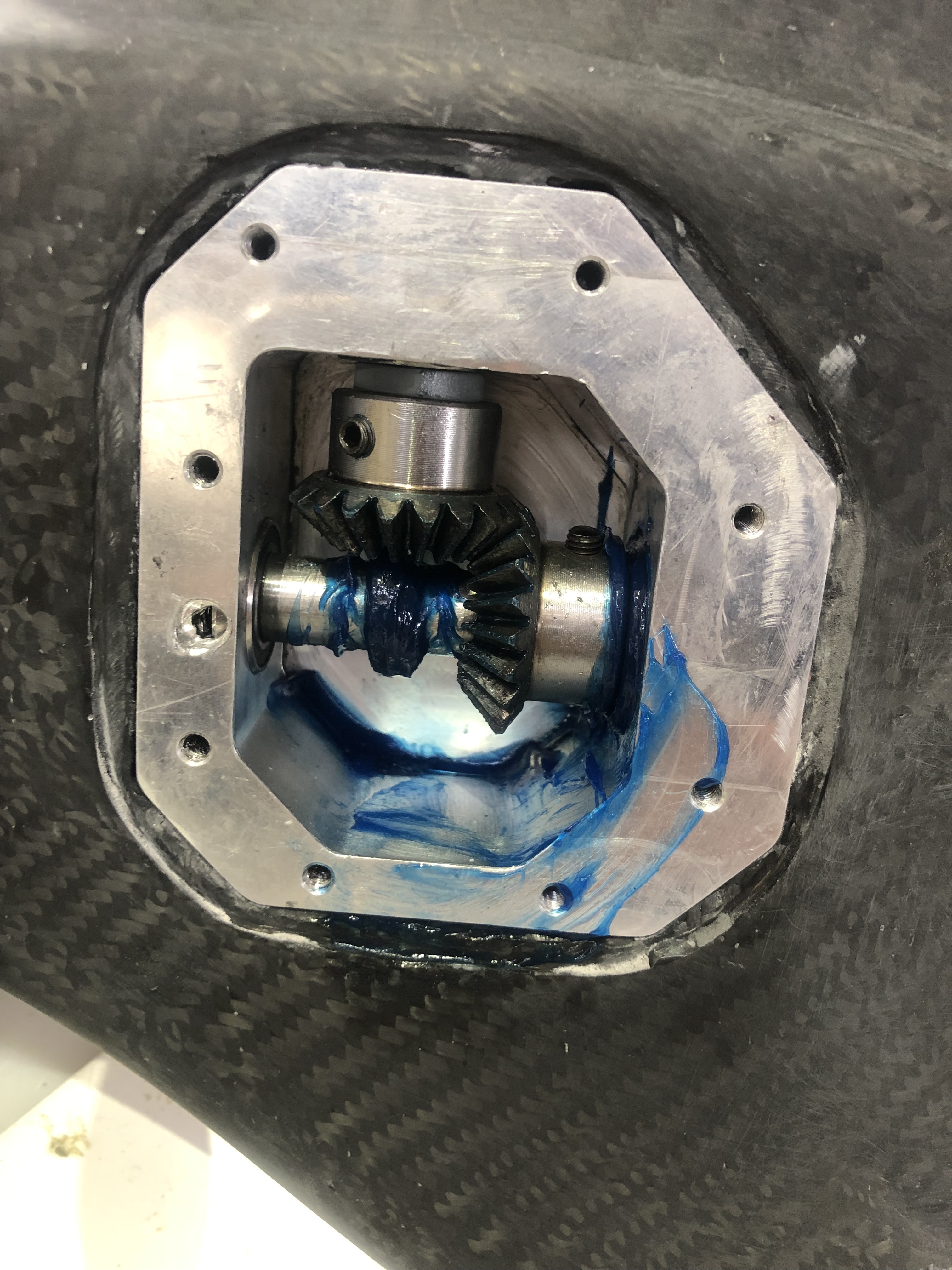
I got the motor for another project, I was going to convert a petrol jet kayak but I knew nothing about these motors and it sat around for ages. I’m not to worried about the thickness at this stage. The gearbox is a simple 1:1 bevel gear setup, aluminium case and oil filled to stop the gears getting to hot and stripping hopefully. I’ll get some pics up later but it’s in bits at the moment.
The prop Is 130mm from aliexpress, so far it seems it will be ok but it’s very heavy.
The battery is 40ah so was quite an expensive mistake. What if I got another one And ran them in parallel, would that make it 60amps continuous and 120 peak. I don’t know much about the electronics yet.
Hi! Ok, its in aluminium i guess? Do you use a 1:1 gear in the angle gearbox?
When i comes to batteries. You need a pack with a C-rate that matches or exceedes your normal usage. The C-rate tells us how much amps we can draw from the pack continous and peak. A 40ah pack with 10C peak and 5C continous can deliver 400A peak (maybe 10 seconds) and 200A continously without overheating or otherwise being damged.
If there is no information regarding C-rate on the pack you need to know who made the cells and get the specs from them. I have never seen a ebike battery that can handle our current demands, but there is always a first 
Putting 2 in parallel will definitely give you double the discharge, but you could be lucky:
-
These batteries are usually build form 18650 cells. There is no 18650 cell with more than 4Ah, so there have to be at least 10 in parallel, my guess is: either 14p or 16 or even more. And every 18650 cell (I am talking about unprotected cells) can deliver at least 5A continuous. So worst case (only 10p and shittiest cells on the market): the battery it self can do min. 50A cont. But it is much more likely that there are not the cheapest cells inside and no high capacity cells, likely some panasonic or sony with ~2.6Ah, so ~14p-16p and each has a discharge rating of ~7-15A so at least 100A cont.
-
There are EV cells inside (not very likely, but possible) which are made for high capacity and >2000 cycles, so they usually (e.g. in solar power plant) have many other cells parallel and so they are simply not made for high discharge. But these are pouch cells and many of them also have a discharge rating of 2-5C (like these) but there are always exceptions (like these).
So back to topic, why does your pack only give you 30-60A:
All of these assembled batteries you buy, do have a battery management system. This controls and ensures safe (for you (fire) and the battery (overdischarge)) charging and discharging. But also the battery management limits the power you can draw, even if the battery can do much more.
So why does a battery costing >500$ capable of >100A do have a BMS with 30A limit?
Well $$$, look for some BMS, you can get a 13S 10A BMS for 7$, but a 13S 150A BMS is close to 150$.
I would recommend to have a closer look at the battery (many battery builders put a label on the battery with the used cells and configuration) and get to know what is inside. I am sure you can find someone close to you who is able to upgrade/exchange your BMS.
Also bear in mind where you want to go. There are people flying with much less than 1,5kW (==> much less than 30A @ 14S). Sure this also depends on system, wings, weight… and before takeoff you will need >30A anyway. But consuming more than 50A cont. also means much more trouble everywhere (cooling design, cables, connectors, ESC…).
That looks amazing. I like it a lot! How will you control the attitude on top of the water? Flaps?
you make a valid point here, i might leave it for now and see how it goes, maybe try reducing propeller pitch to keep the amps down. i made a mistake, its a 30ah battery not 40ah. the cells are 18650 3.7v 3C Samsung, 14s. i’m curious to know what the max discharge current would be with this if it wasn’t limited with the current BMS. (just in case)
Max, i’m no longer planing on controlling the foil with a joystick. i decided its difficult and expensive enough without adding complications so now i’m keeping it simple with a throttle on the paddle. also a hard landing with a joystick between your legs would be quite uncomfortable.
1 Like
Well, you already stated it: if it is a 3C battery: 3x capacity = 90A cont.
That will keep the motor amps down (less torque needed) but also the max. velocity.
Maybe have a look in motor amps vs battery amps. And have a look into ESCs, basically the ESC can let flow more amps on the motorside than on the battery side (think of a stalling motor, 0 rpm means 0 energy (neglegting heatlosses), still you can have high torque, this torque is produced by the high motor amps and near 0 battery amps, which are again 0 energy).
So you can have the same effect of the smaller prop by limiting the batterypower/rpm at the ESC and allowing higher amps on the motor side (but your motor mustnt get too hot). Not perfect efficiency wise (higher losses in the ESC and motor) but good enough for testing…cheaper than having 10 different props…
thanks for the advise Giga, i might order a BMS just because everything takes so long to arrive but other than that i’ll see how what i’ve got goes. i’m probably not far enough along to be worrying about how ti get the thing working yet. i had the motor running and for me that was a huge milestone.
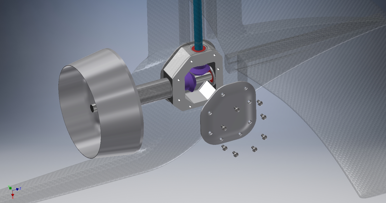
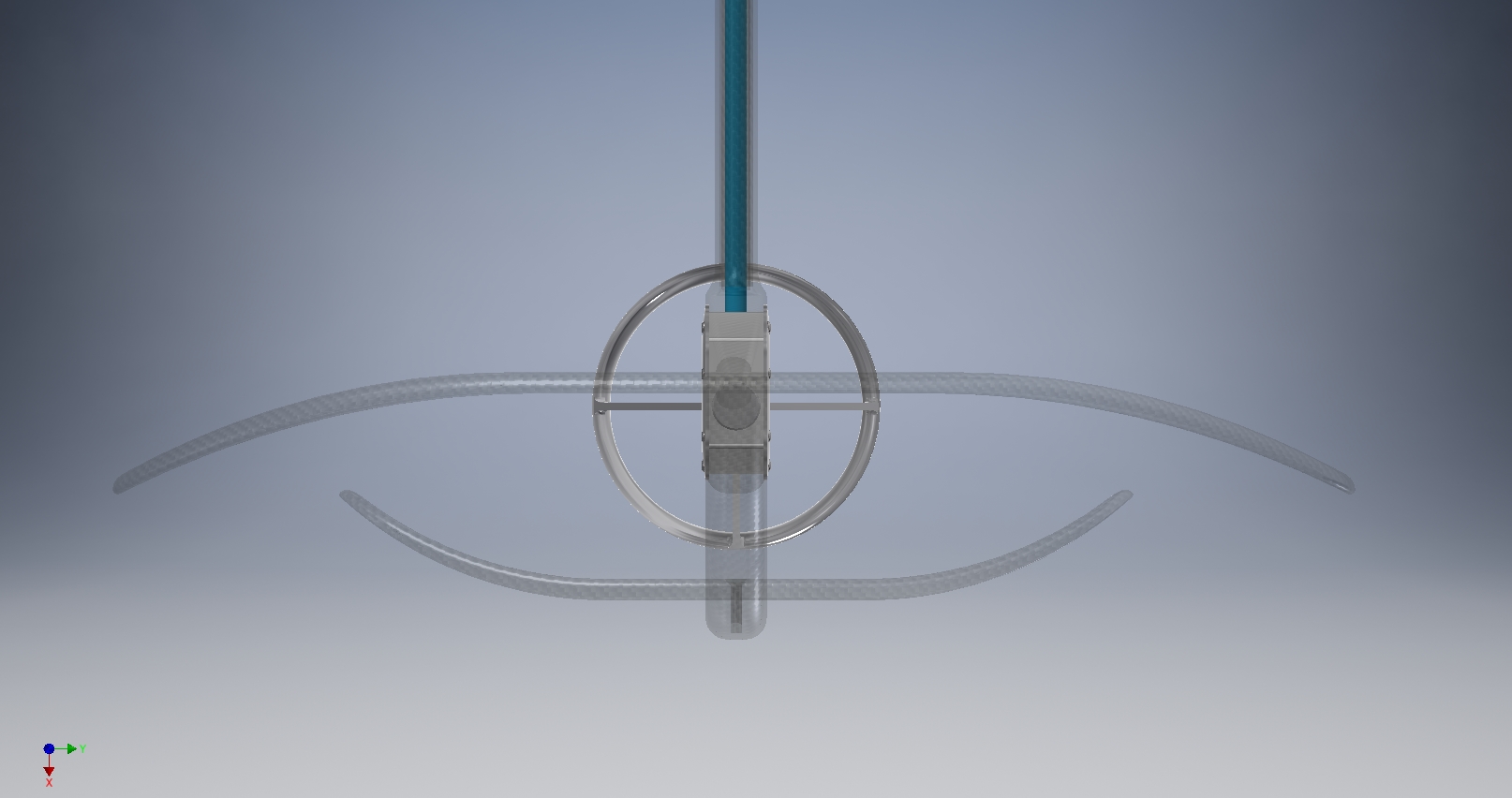
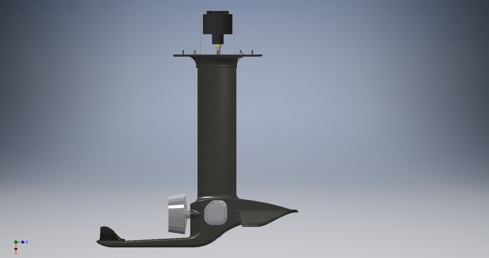
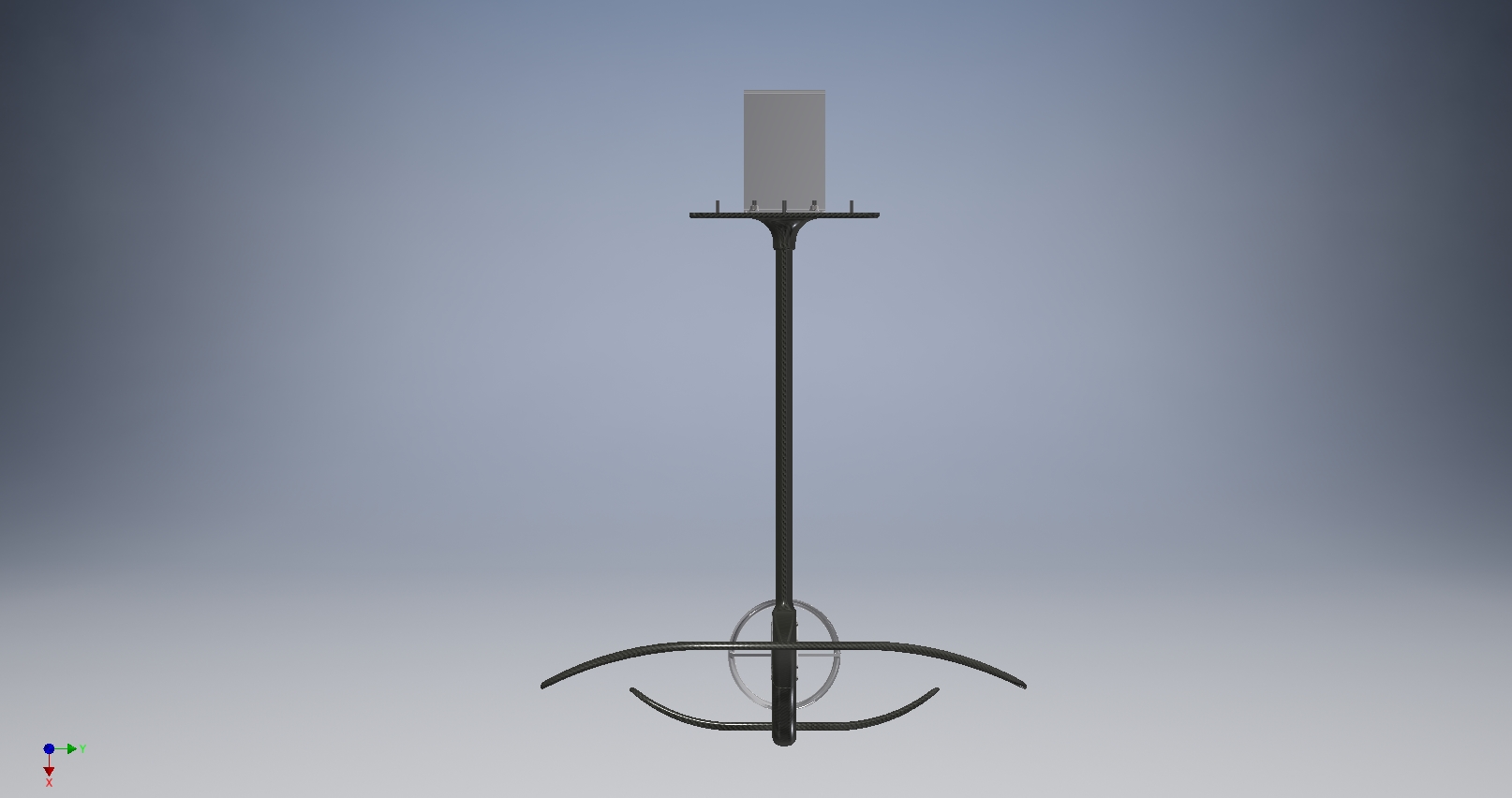
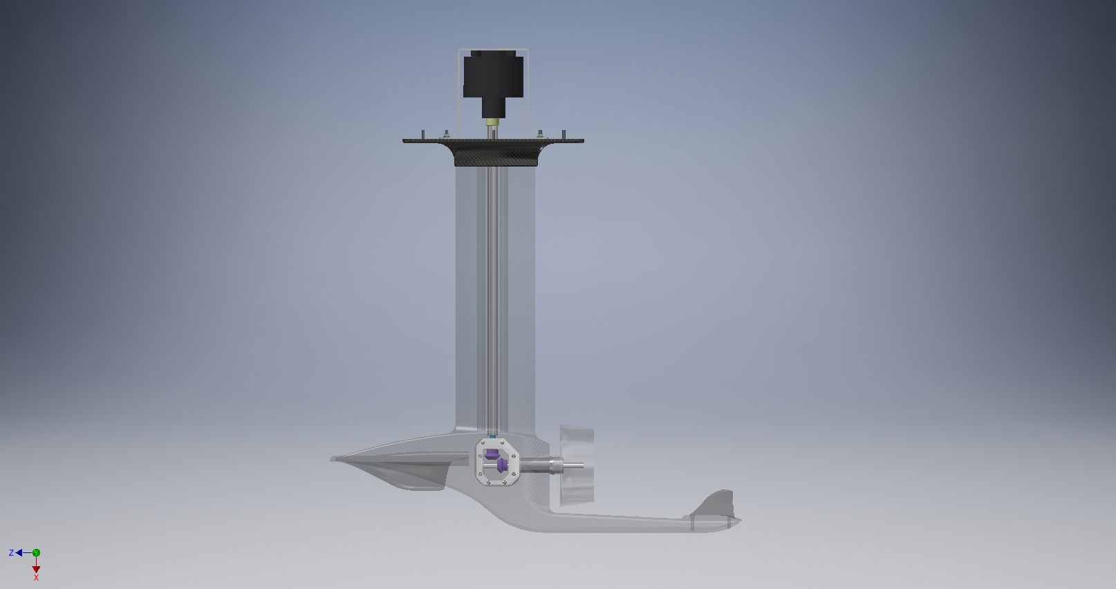
i’m currently working on the mast / gearbox assembly and trying to make a mold for the mast but it didn’t go well. pictures attached of what it should look like.

2 Likes


Progress report…
I’ve got quite a bit done in the last week but my holiday has ended now so it will probably slow down.
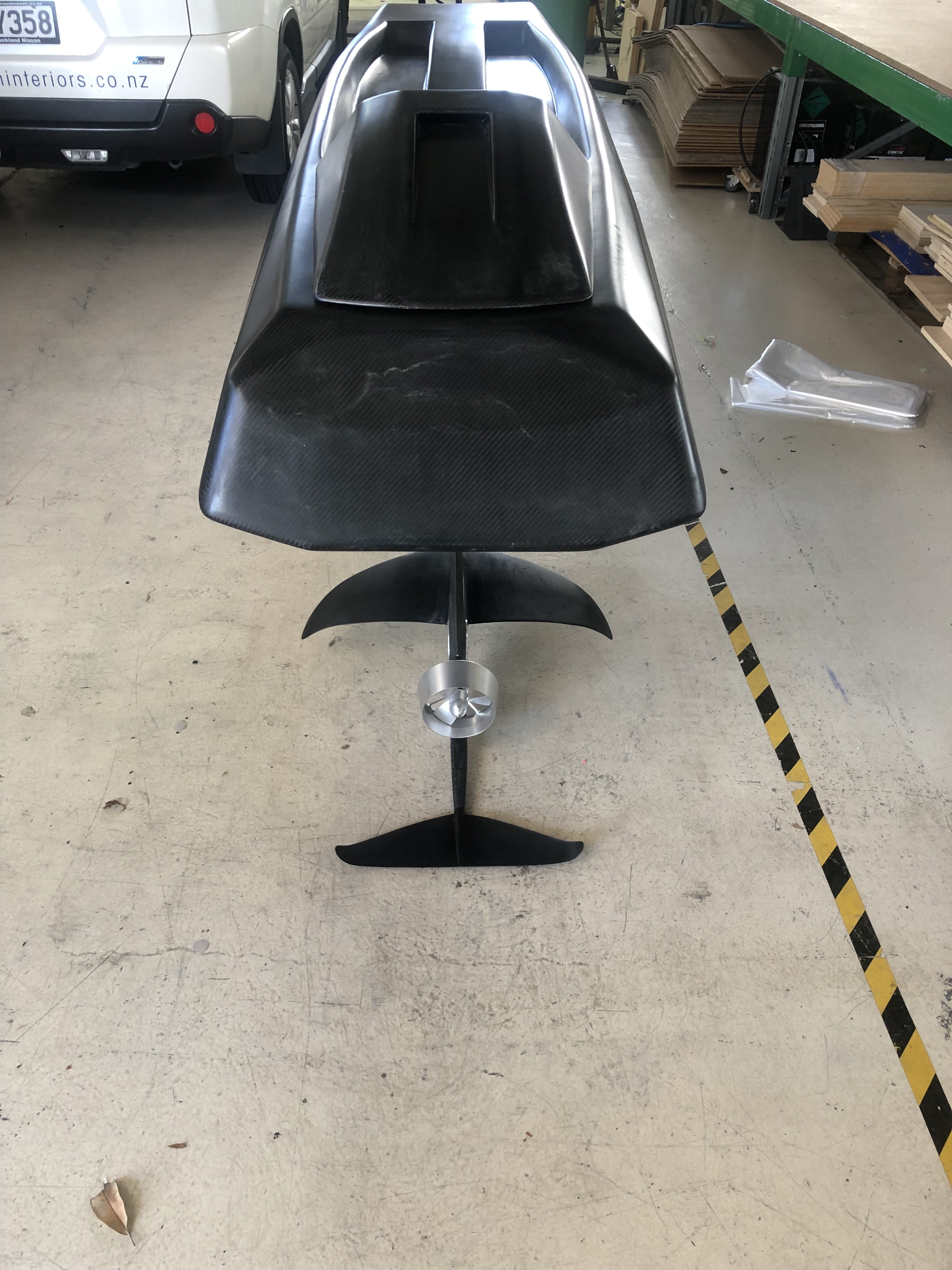
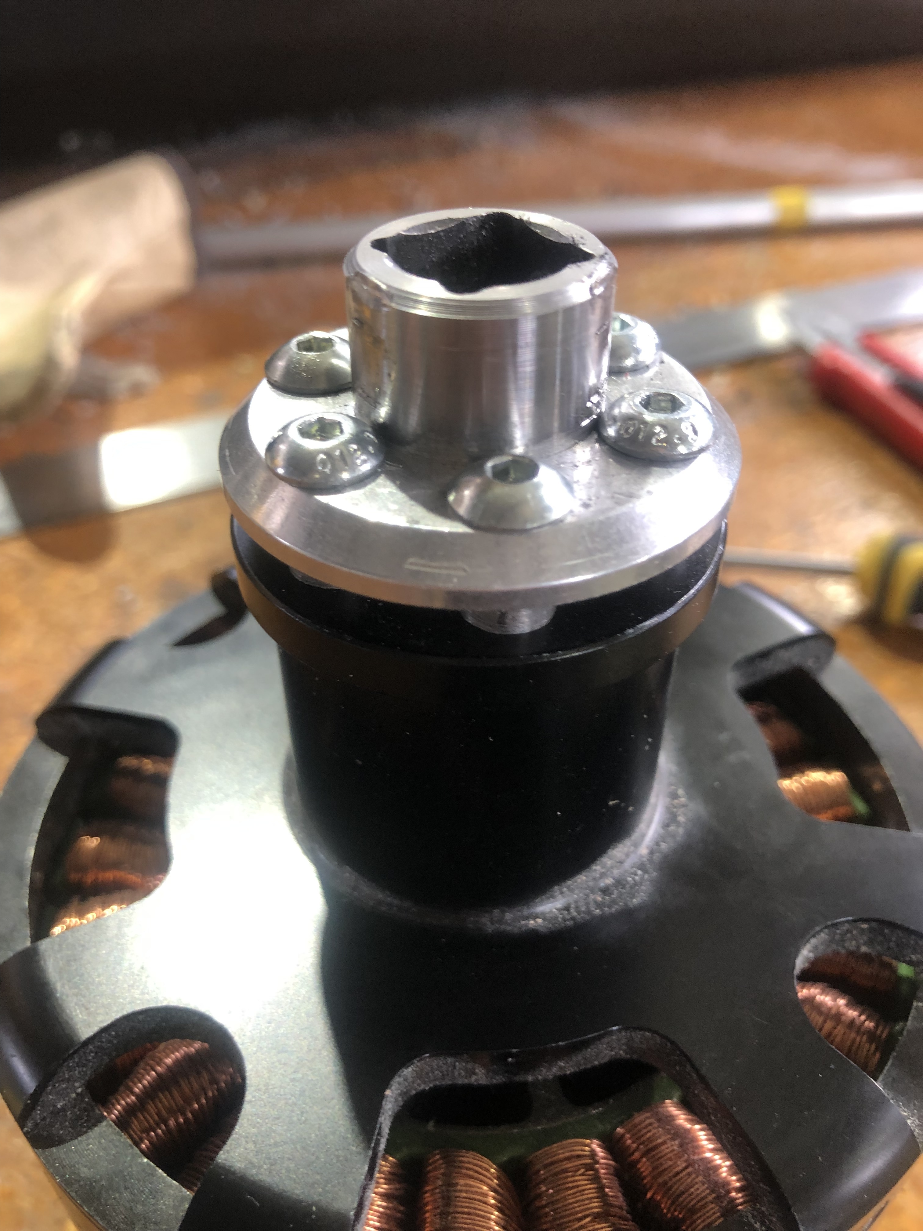
The mast is complete with drive shaft, gears and coupling in place. There is quite a bit of resistance and a bit of vibration, mainly due to the shaft not being perfectly straight. Has anyone else done a shaft in the mast? I added a brass bush half way down which helped. For the coupling I just raided the tool chest and used socket parts with a bit of lathe work. The whole thing feels heavier than I planned, way to much carbon I think, I am an amateur with carbon and have no concept of how much I need, the mast is virtually solid whereas the hull might be a bit weak due to my learn as you go approach. I’m already thinking of building another one and this one hasn’t even been wet yet.
All I need to do to finish is make a motor mount and sort out the electrical stuff. I’ll draw an electrical diagram soon with all the stuff I want to incorporate and hopefully someone can tell me where the wires go.


1 Like
I’ve got a bearing at the top, half way down, and bottom my drive shaft. I’ve had very little vibration from my drive shaft during a short tests with it in.
Hi Daniel, what’s your drive shaft made of. I used 12mm stainless but can’t find a straight piece. I have roller bearings top and bottom with a brass bush mid mast, so much the same as yours. I’ve only tested with a cordless drill and vibrations were worse at low rpm. I’m thinking next time I might try a smaller diameter rod that’s more flexible but in a ridged tube that’s lined with a ptfe tube so it’s supported all the way and lighter.
I’m using a 6mm mild steel rod welded directly to the input shaft on my gear box. I was getting too much vibration from a coupler and wanted the total size under .5".
My mast is a .5" x 1.5" welded steel core with a 3d printed fairing around it. The drive shaft runs through the 3d printed part. The top and mid bearings are in 1" aluminum square tube segments so they are against aluminum not plastic.

1 Like
I’ve tested so far with a 6s battery but once my second battery arrives and I can do a full power 12s thrust test I’ll do a proper build post.
very nice idea! love this concept, please keep us updated!!
Hi Daniel, any progress on yours? I’m stalled waiting for a speed controller. I’m curious to know how the 6mm drive shaft holds up under load.
Did a short full power test. My shaft held up fine but some other parts not so much, I’m using a chain reduction at the board end so my total reduction is around 5:1. Apparently my chain got a bit hot because it started smoking some of the links seized solid. I’m going to make up a new chain and make a housing around it that can hold some grease in. The other option is to make up a longer chain so it has time to cool between sprockets. My other issue was my motor was twisting in its mount so I need a better way of mounting the motor.
Got 15kg of thrust out of it so far. Aiming for over 20kg but I feel like it was a decent start.
This is still basic my setup
I’ve made a lot of changes but the same concept.
Good to hear about the shaft, I haven’t had mine running in the hull yet but I think vibrations will make it loud. Surprised to hear about the chain, if it’s getting that hot it must be running well beyond its capacity, be careful, imagine the damage it would do if it broke. I don’t know much about chains but I think whilst grease will prolong the life of the chain but it will eventually just create a whole lot of smoke as most of it will flick off due to the high rpm. An oil bath might be better so the oil is always in contact with the chain and able to circulate so it can be cooled, but a challenge to contain the oil. I’m fortunate enough to have accidentally purchased a giant overkill low KV motor so I can go 1:1 direct drive so I only have the lower gearbox to worry about. My coupling is metal to metal so that will get hot and probably fail at some point, failure leads to innovation though right.
Just looked it up (I know… It’s the sort of thing I should have done first). Tensile strength of #35 roller chain is 800 kg. The chain breaking is pretty low on my list of fears. Now a sprocket coming loose and the chain launching is a little scarier, but it going to be encased in plastic and plywood so should be pretty contained if it decides to grenade.