That could well be my problem - I’m running mine at the end of an extension cord, and only on a 20A circuit. I’ve never blown a breaker, but I definitely brownout the whole shop every time I fire the thing.
Never occurred to me to read the directions.
Probably be easier to build a lead-acid battery based welder than it will to add a 40A circuit.
I think, if you are running a 110 version on a extension cord there is room for improvement. Probably a significant portion of your available voltage is being burned up as heat in the wall and in the cord.
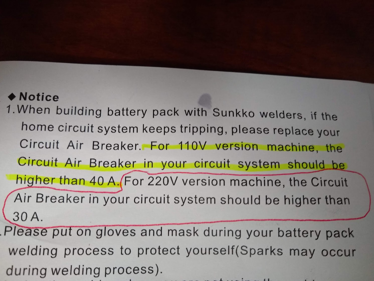
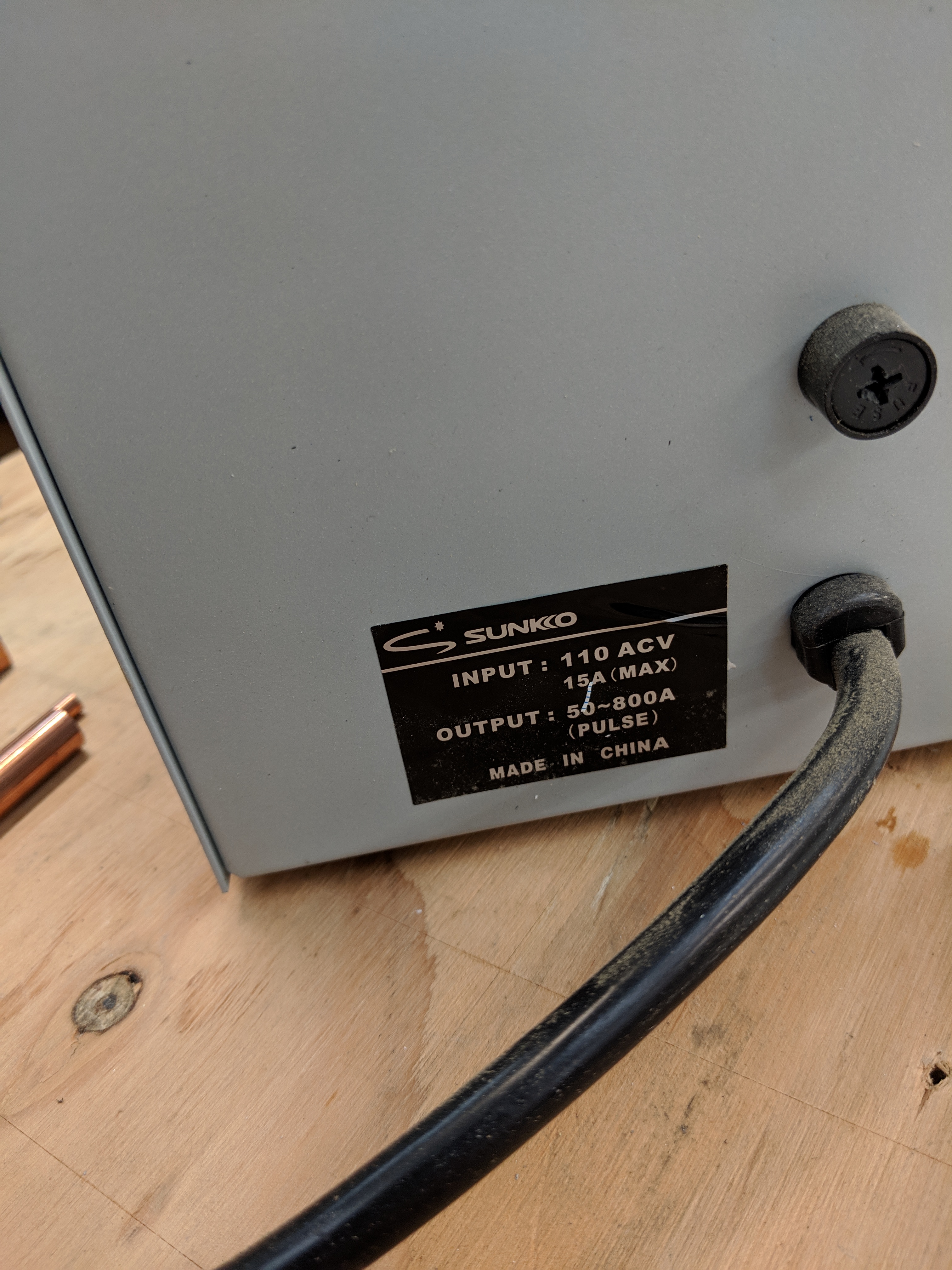
In the case of your 110 version spot welder, I assume it has a 110V 15 Amp plug, or maybe 110V 20 Amp plug. If your running it on a extension cord I would guess its only a 15A plug. No electrician is going to fuse and wire a 110V 15/20 Amp outlet. with a 40 Amp breaker and wire. The wire is to big to be connected to the outlet. The outlet would fail before the breaker. So it does not make sense to me.
It does seem clear to me that the 110 version needs every bit of voltage it can get to do the job.
Having said that. My 220 VAC spot welder was supplied with a 10 Amp plug. The wires are tiny. I am running it on a 220 vac 20 AMP outlet I normally use for a small plasma cutter. The outlet is 20 Amps fused, wired with number 12 wire. The lights do not dim when I use it with the spot welder.
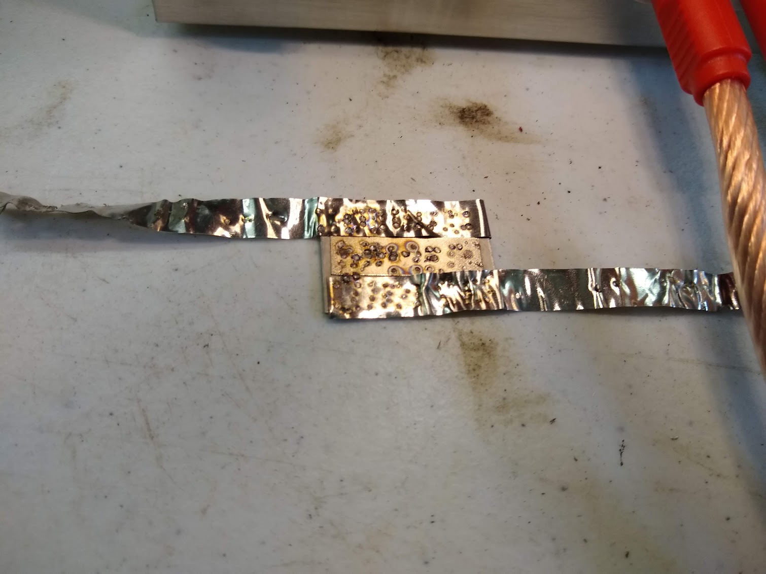
The welder came with a small 1" by 1" piece of metal with a 1" nickle strip spot welded to it. That’s in the center of the photo. It must be a test they do at the factory and include it as quality proof.
The pieces connected are pure nickel. Its bent because I would try to tear it off after I made the weld. Just experimenting.
It looks more brown in the photo than it actually is. Lots of different settings in that photo. Sometimes spark, sometimes the electrodes stick to the work piece. Sometimes it would make a hole in the material.
Also, they appear to be suggesting that you replace the 15A breaker in your panel with a 40A breaker without upgrading the wiring. Seems a bit ill conceived…
In my case since the thing worked great when I first got it and doesn’t work as well now I’m assuming a component is degrading.
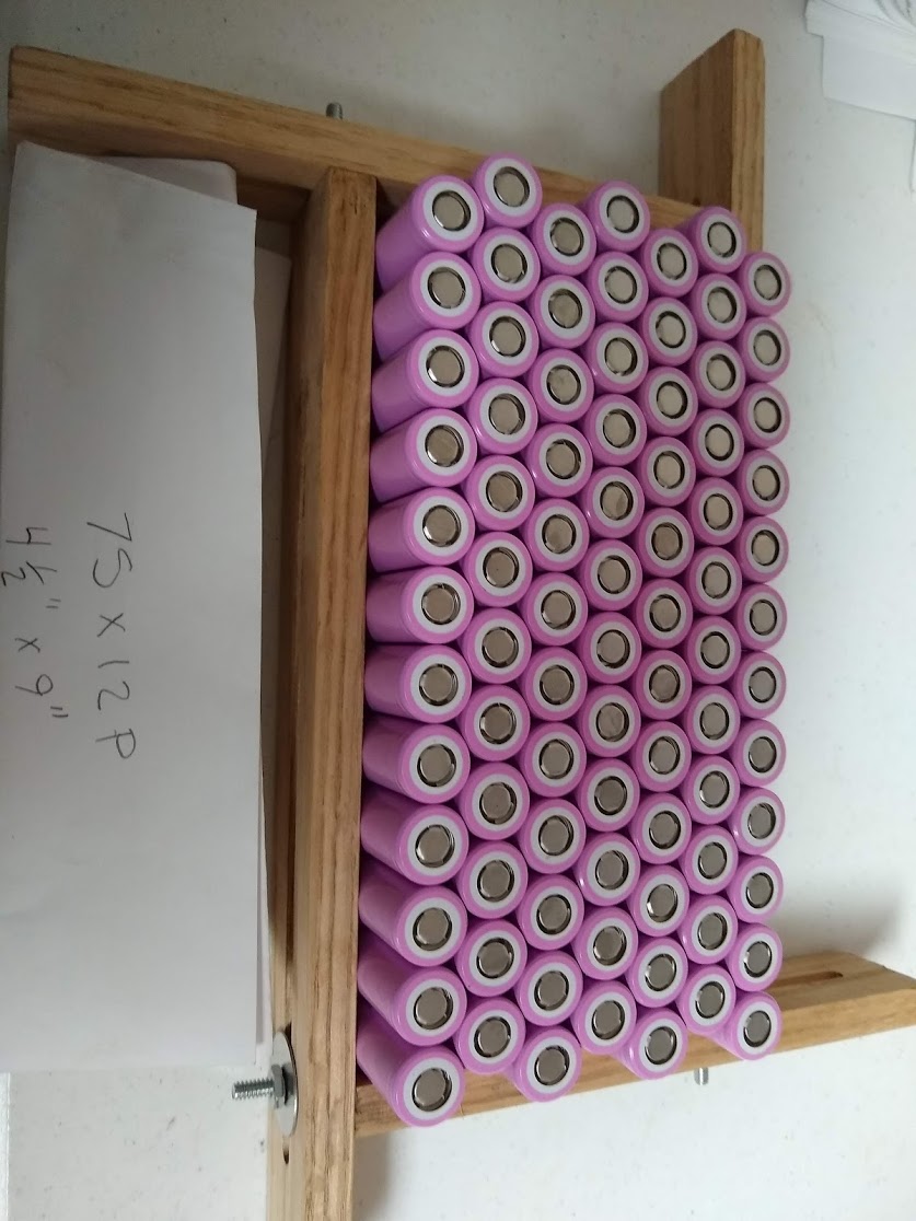
Are you planning to separate your cells/ s-groups mechanically?
If not, I would recommend you to, since from one s-group to another there will be only the thin pink PVC sleeve separating your cells (both cans of neighboring s-groups are negative but have 3,7V potential difference) and as soon as you use your battery pack/have vibrations those cells will (slightly) rub against each other till they short somewhere.
So depending on how you will fix them mechanically that might be more or less an issue.
I think your right. Thank you for the warning. My spot for the batteries has no extra room. I was not even going to use hot glue because I was afraid that would take up extra room. I was planning on just letting the spot welds and a little tape keep things tight. Hopefully I would have enough room on the out side for a layer of heat shrink.
Now I am thinking 1 layer of some kind of tape between the series cell groups. If it grows too big I could redesign my electrical components to use less space.
The weak spot in around the top edge on the cell , it is nice go add a isolation ring on the + , and for the Heat of the nickel strip
Kapton tape for the rest
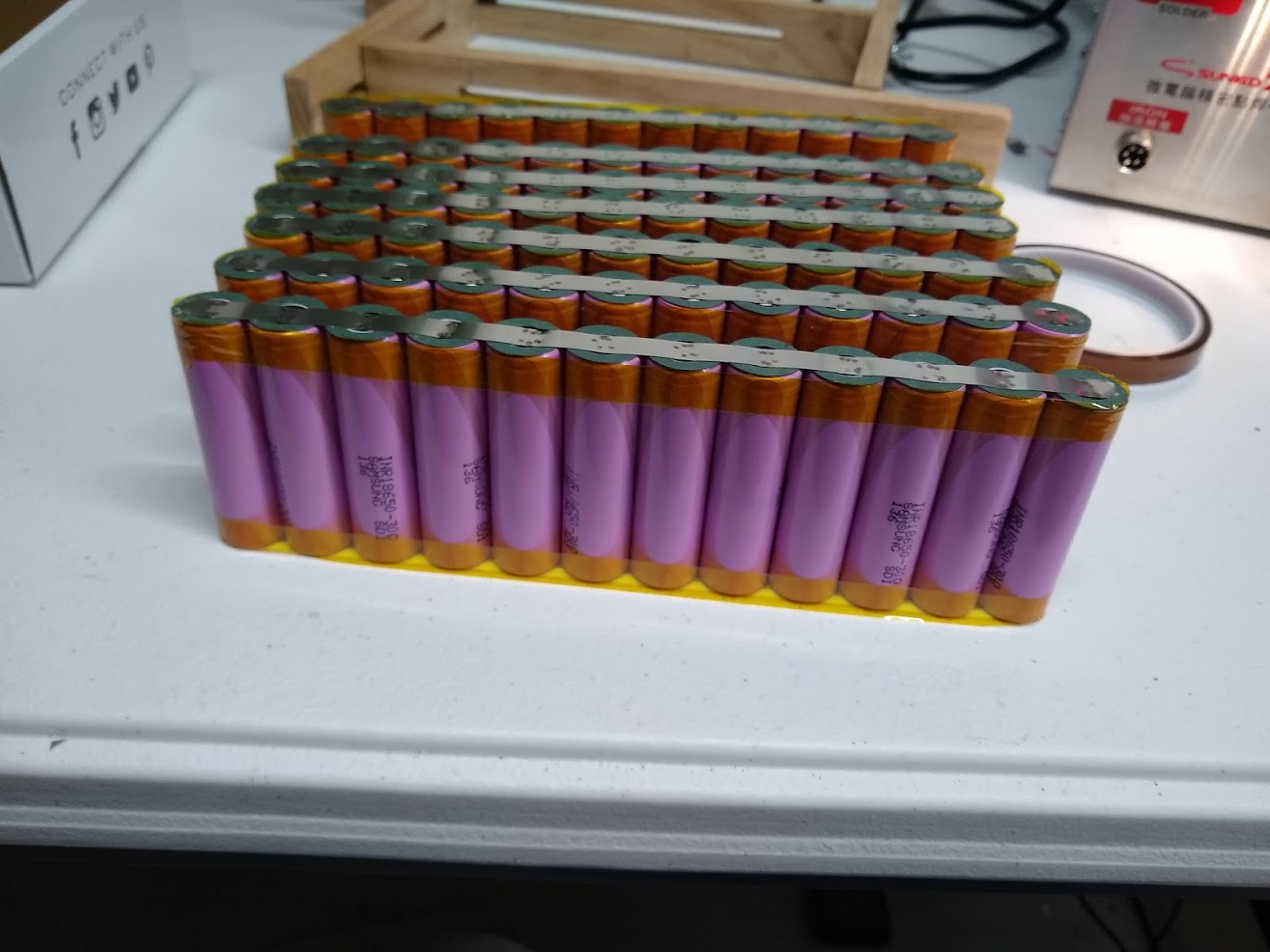
I did a quick voltage test of each battery, all were within 1/100 of a volt. I placed
insulator on every positive side of each cell. I wrapped each parallel group Kapton tape.
I did quite a bit of tests spot welds before I began. I tried lots of settings, I am not absolutely certain that my welds are good. None of the “for score” ones broke off, but I did not try that hard to break them off either.
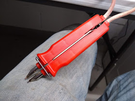
I did all my welds with the hand held tool, rather than the tool mounted to the spot welder. The hand held tool gets very hot, to the point it is hard to hold onto. The hand held tool also starts to melt and the spacing of the electrodes becomes sloppy.
I operated at full power and almost full pulses. The heavy gauge wires that power the hand held tool jump and get hot each time you make a weld.
Much of the available power is lost in the hand held tool wires.
The electrodes that are mounted to the welder seem to have much more power. But they are difficult to use on a large battery.
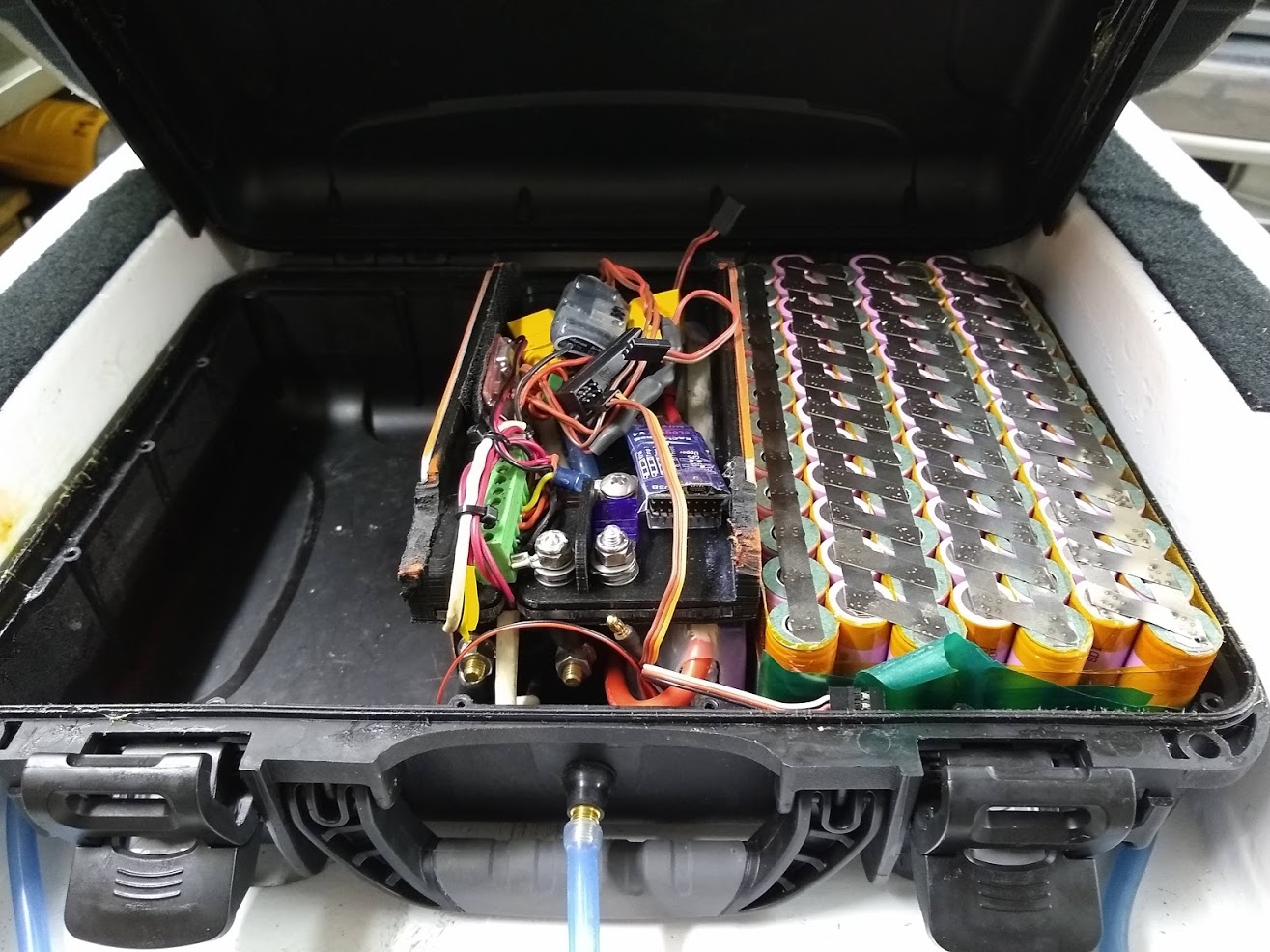
I managed to keep my batteries as tight as possible, Unfortunately they still slightly interfere with the enclosure lid closing. I need a additional 1/4" space on each side to fit all the batteries in.
No room there. I only have about 1/2" above the batteries. That orange aluminum frame that sticking up on each side of my electronics has 3.5" between them. That frame helps support the lid when the lid is closed. I did that so I could put all my weight on the box without it crushing in.
As far as the buss bar goes Its nothing special. I took some 10 gauge super worm silicone wire and pulled the insulation off it. There 7 bundles of strands inside. I evenly distributed them along the length of the nickel. I decided to go with 10 gauge rather than 8 gauge because I plan to use XT90 connectors. I sanded the Nickel strip before I soldered. I tried to be quick with the solder operations so I would not damage the batteries.
I’m using nickel strip for my packs. I have a continuous roll. I’m not sure if it is really only nickel or nickel coated steel (e.g. hilumin by tata steel). The steel ones probably have higher resistance, but I don’t care too much as the current between cells in parallel should be very low anyway.
I would recomment first soldering and then spot welding to the cells, too.
I’m not sure about your setup, but I can spot weld another strip of nickel over the first one to decrease resistance. I soldered a solid copper rod to the last nickel strips, this collects all the current from the parallel cells.
I would recommend testing the spot welds on some old lapop pc cells or other test cells. Fine tuing the settings and the pressure with the hand tool really pays off. Too low pressure on the contacts and you throw molten metal around, with too high pressure you deform the battery housing…
With the test cells I usally made 4 test spots on the positive side to attach a nickel strip. You can then pull of the nickel strip. It should really leave holes in the nickel and parts of nickel on the battery.
Do not use the negative side of the battery for tests as a failed spot weld or when ripping of the nickel from a good one can leave holes in the metal battery can. This exposes the inner fluids