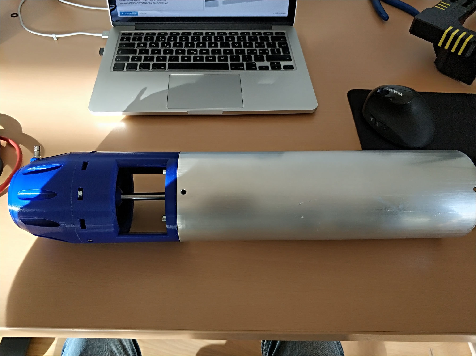
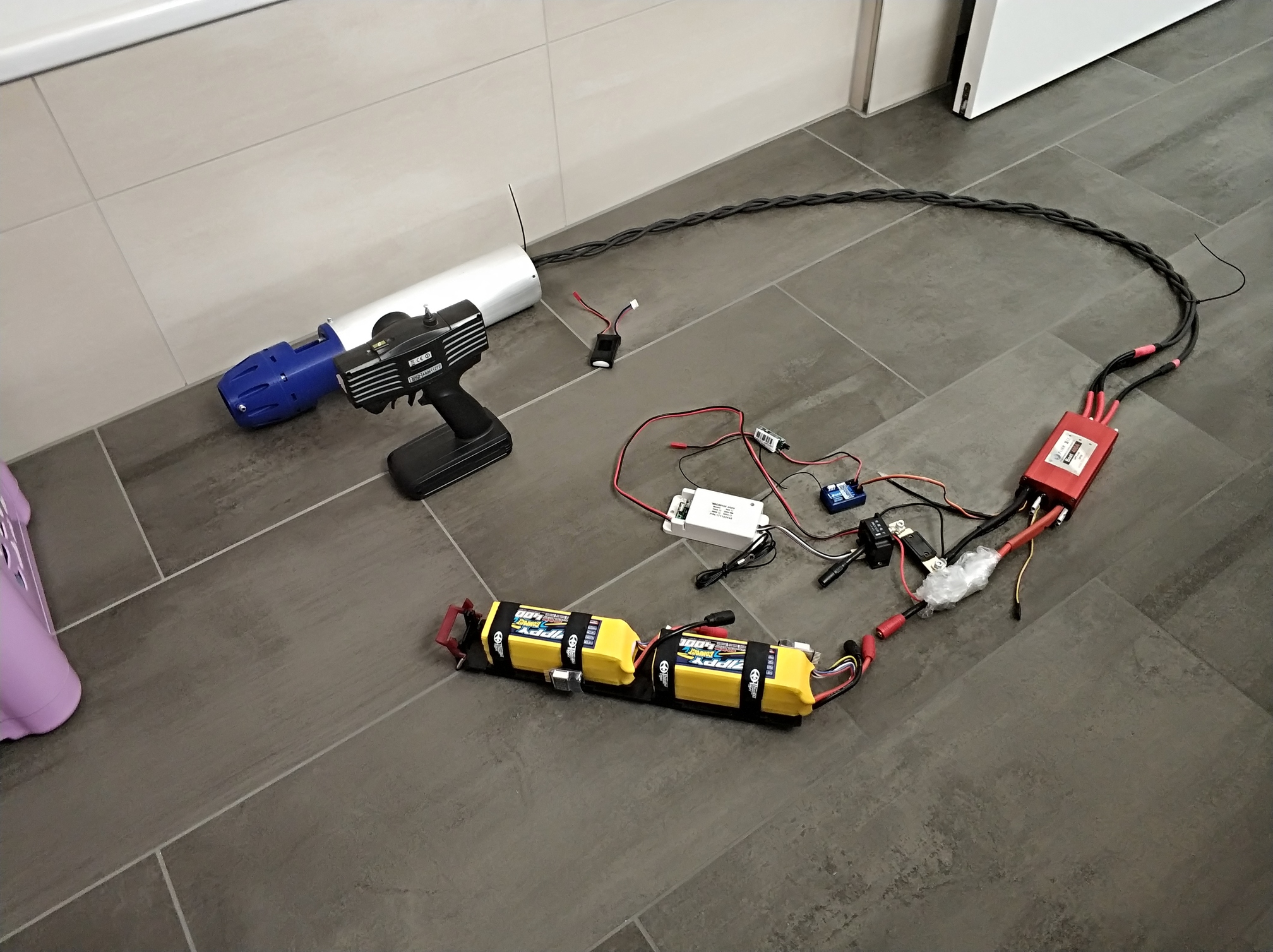
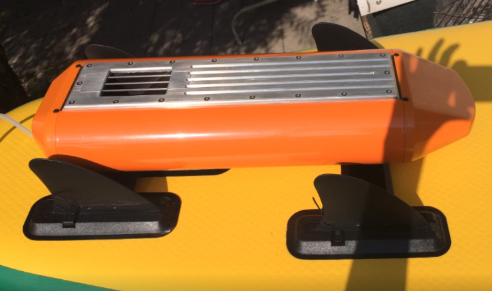
Hello I am Kevin and I am building a jet drive for my windsurfing board.
I use the following components:
Flier Boat 400A ESC
SSS56114 / 500KV engine (I think I will switch to the 790KV engine)
2x 6S 4000mAh Lipo from my helicopter
Capacitor bank with 10x Low ESR 330mF (to reduce ripple voltage and safe the ESC)
DC Hall sensor Ampere meter
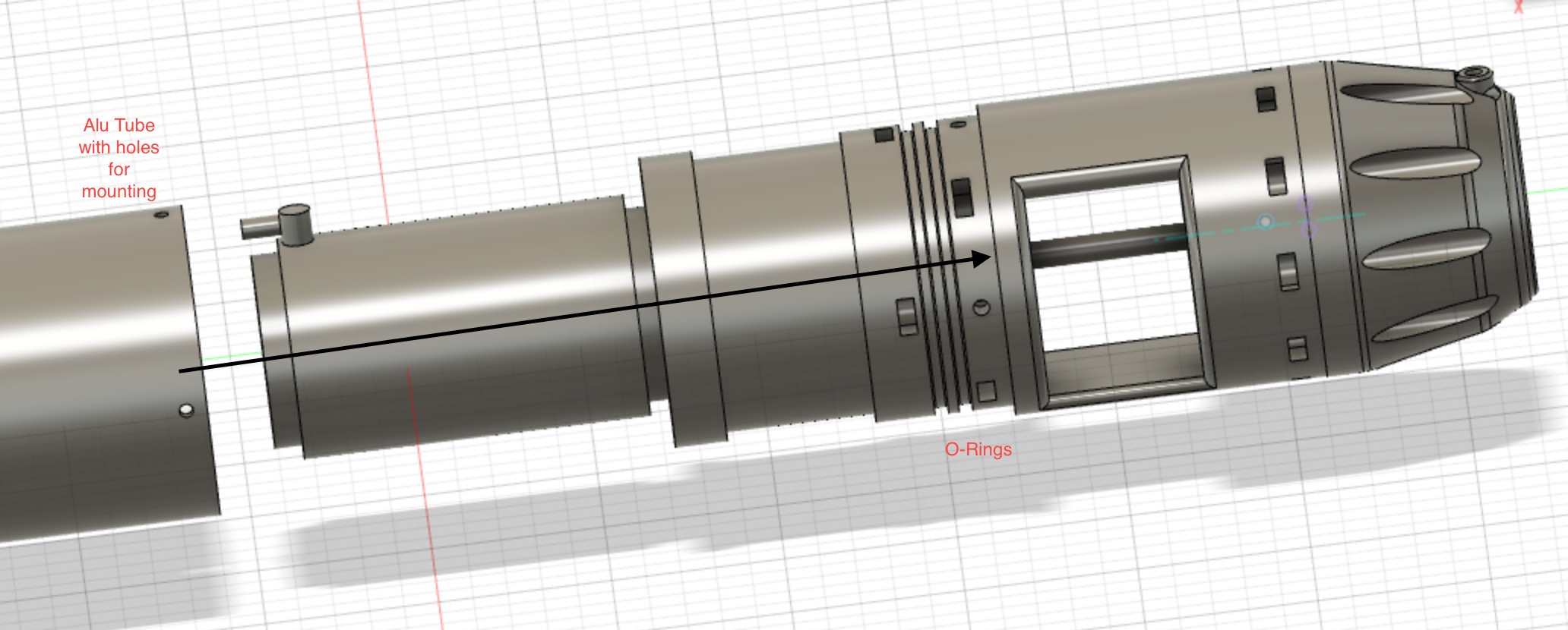
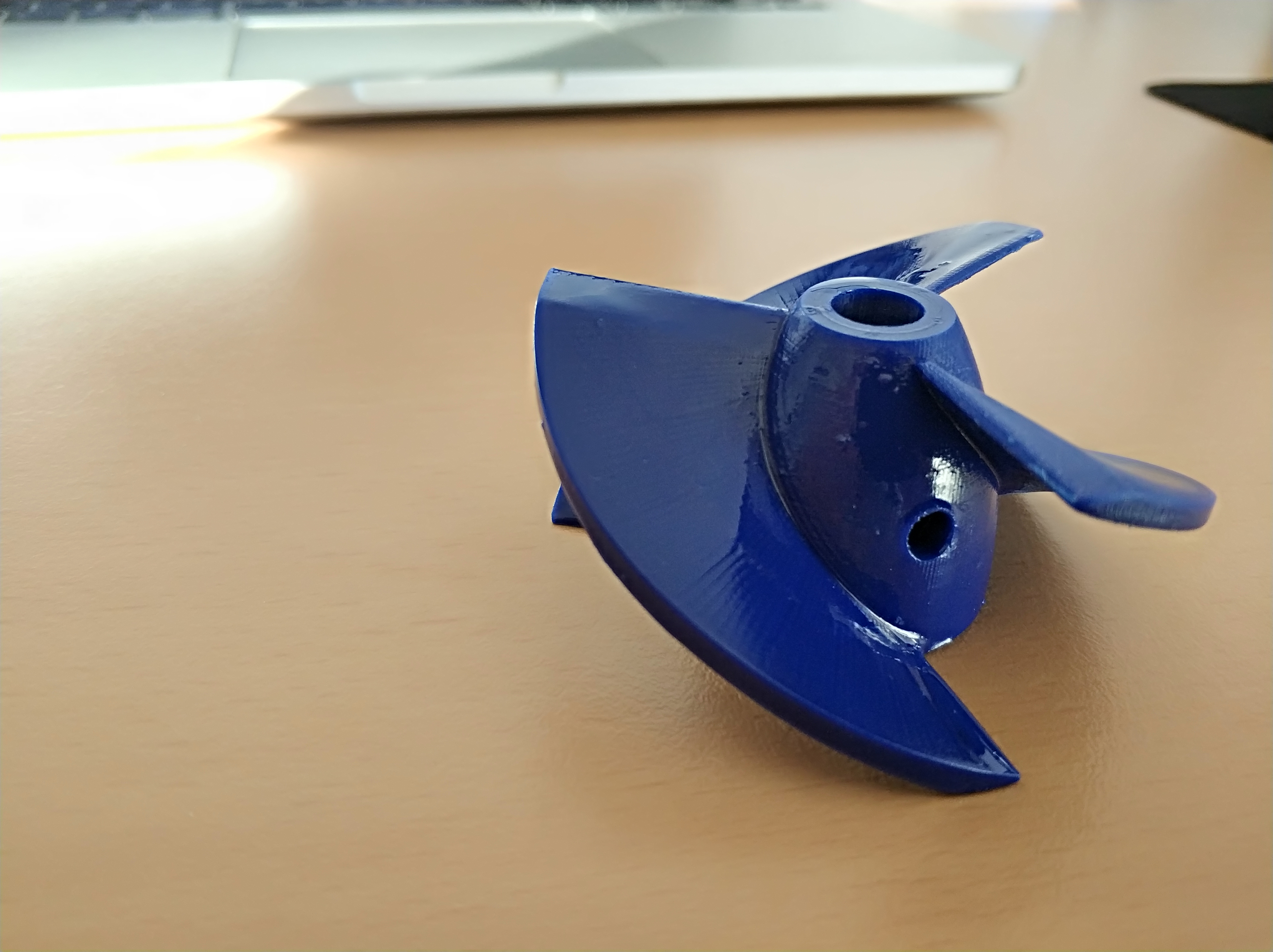
Many components I have printed with my Anycubic with PLA+ and PETG.
The first results are good: about 12Kg thrust, with 6S Lipo and 60A current consumption. Motor and ESC stays cool. But will later be water cooled. There is still potential for optimization. My next test will be with 12S Lipo, but the better option is probably to use the SSS56114 / 790 with 6S.
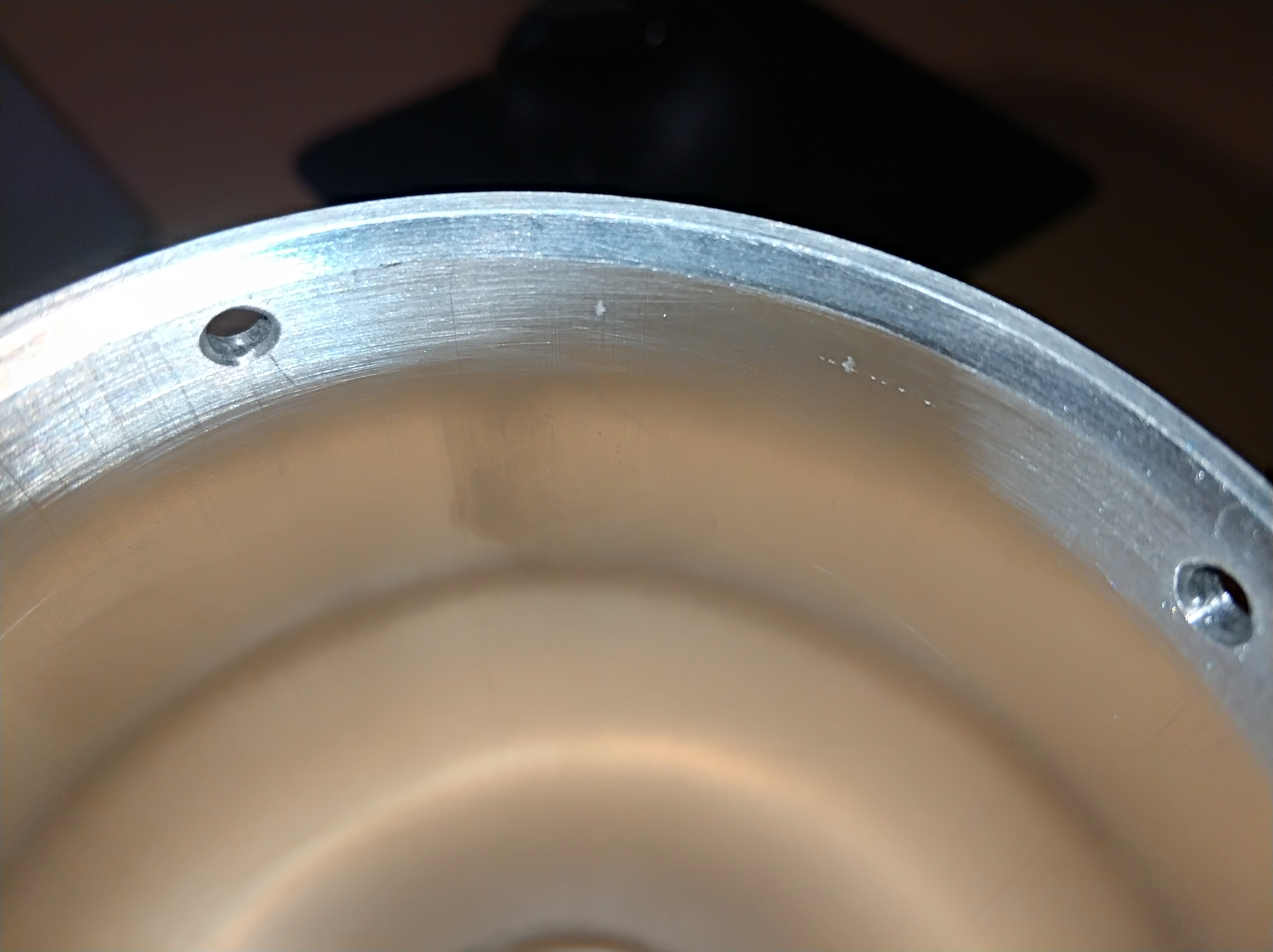
Currently I have the problem that the o-rings get broken when I push the drive into the aluminium tube, because they are pushed over the hole in the aluminium tube.
How did you solve this? Is the pressure for the O-Rings possibly too high?
I machined the part with the grooves for the o-rings yesterday and I had the same problem when I tested the fit, I destroyed one o-ring. I had to make the groove deeper. You also need to lubricate it, I use silicon grease.
Regarding the orings, it may help to counterbore the inside of the hole to remove any sharp edges. Silicone grease or other lubricants may also help with this installation issue.
Larger width orings have a tendency not to brake as easy. I always try to use the larger orings.
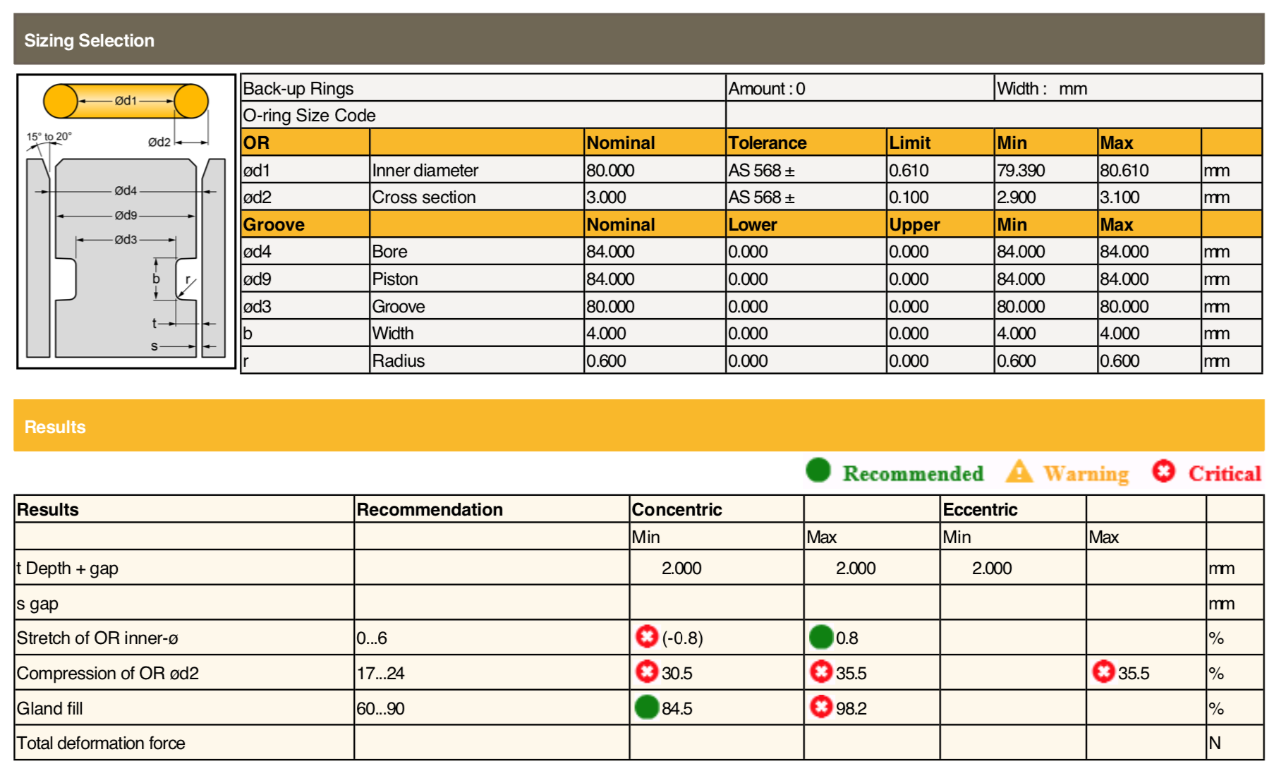
I use two 80x3mm O-rings and lubricated the aluminium tube. But the pressure was very high. Currently I can’t get the aluminium tube down anymore. The pipe is stuck.
I have already turned a phase on the aluminium tube. But its a good idea to try thicker O-Rings or make the groove deeper.
What are you using as CAD software ? Orings groove are all standardized. I have an option in Inventor that calculate the best Oring / groove combination for my piece. You should have something similar I guess.
Hi.
I would make a longer phase with less degrees because the o-rings seals behind the holes - additional you can optimize your 3d-printed part to center the tube with the longer phase.
Two years ago I made a jet-drive for a SUP with a MHZ jet - so very similar to yours - I would go to 12S with the 360kv motor to have less amps - at least I have the SSS 56123/360KV with good results.
All the o-ring calculators are based on high preasure - we have very low preasure.
Mike
but how do I find the right o-ring for the inner diameter (84mm) of the aluminium tube ?
Does anyone know a calculator where you can enter the diameter of the aluminium pipe and calculate all the required dimensions? (o-ring size, groove,…)
Send me your 3D file without the groove. I’ll generate it automatically with the oring on Inventor 2020. I am not into Jet Drive so you can definitely just send the part of the file you want me to modify if you don’t want to share it totally.
You can use this PDF https://static.o-ring.de/or_3.pdf
Take for “Nuttiefe” = dynamisch and for “Nutbreite” = ohne Stützring - allways use grease to mount o-rings - to insert it in the groove and on the surface where it has to slip in.
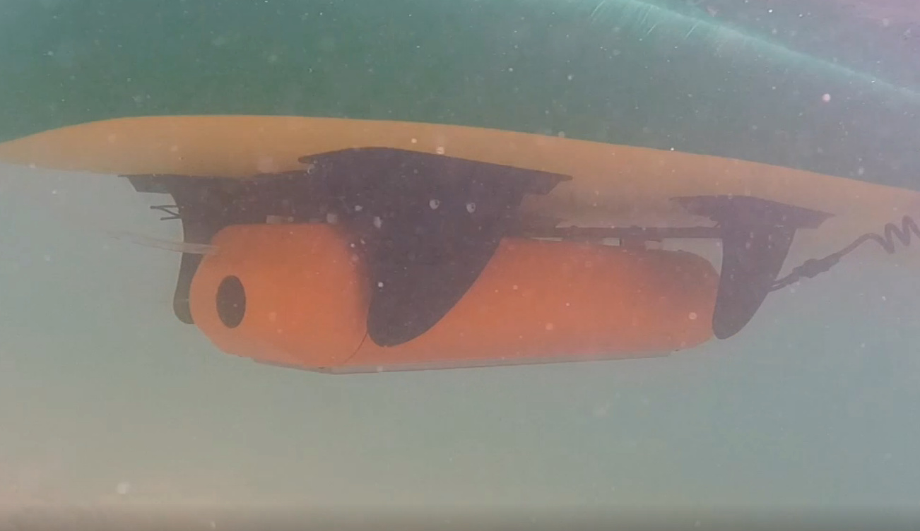
Interesting construction. What was your approximate speed that you reached?
I think an SUP is not designed for higher speeds and does not glide.
I’m curious how efficient the drive on the windsurfing board will be. After all it is designed for planing and early planing. But I have to reach at least 20km/h for it to glide.
Today at noon I found an app from Trelleborg for Android. (Just enter Trelleborg in the Playstore)
In the app the bore diameter is entered and the matching o-ring and groove is calculated. exactly what i was looking for. I will now test the suggestion from the app.
Max. speed was 16kmh - but with 100amp at 10S not really efficient - all in all nearly 4kw.
A similar construction with outrunner and propeller need less than half.
A electic power SUP or windsurfing board is a nice thing - but believe me, once you are efoiling that’s all you want


 and not posted.

