Hello everybody,
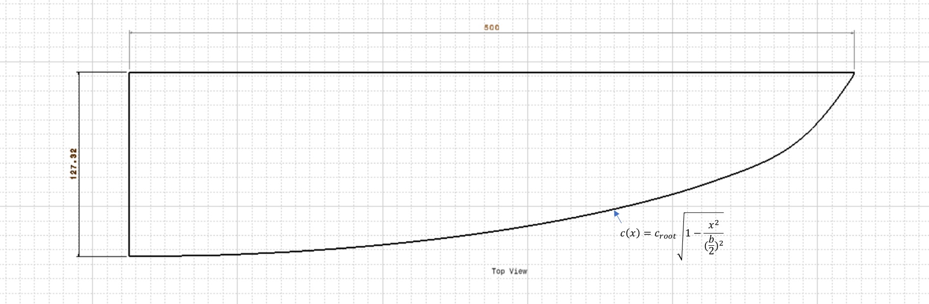
I have been designing a hydrofoil lately and have tried to optimize it for the lift over drag ratio. Up to this point, I have only been designing the main wing. The requirements for the main wing is for it to have a wingspan of 1m and an area of 0.1m^2. I have also designed it to have an elliptical lift distribution to minimize induced drag. The root cord is 12.7cm and I am designing it to foil at 5m/s.
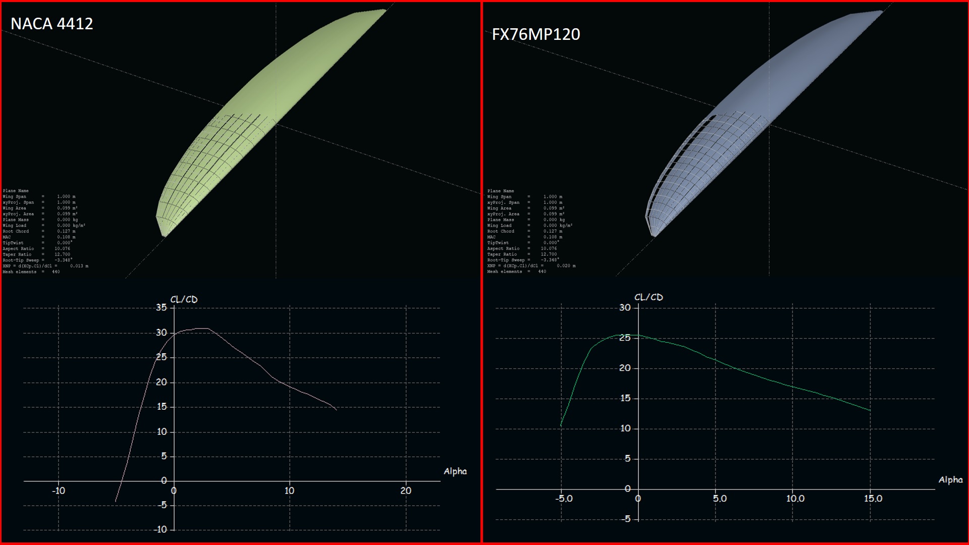
For the airfoil initially, I was using the airfoil with the highest L/D at my Reynolds number (which goes from 280 000 to 650 000, since the chord of the wing changes along the wingspan). The airfoil that had the best L/D ratio was the FX76MP120 for Reynolds numbers around 500 000. Therefore I designed the wing with the FX76MP120 airfoil.
However, when I simulate this wing in XFLR5 I get a L/D ratio of 26 which is quite a low value.
Then I simulated the exact same wing with the NACA4412 airfoil (which has a lower L/D ratio than the FX76MP120) and this wing surprisingly had a L/D ratio of 31. I have added screenshots of the results of the XFLR5.
This result confused me since I expected the wing with the FX76MP120 airfoil to have a better L/D ratio. I am not sure how to select the right airfoil for my wing now.
For these tests, i used the XFLR5 software. Below are some screenshots of the tests with the two different airfoils.
The equation on the drawing is the length of the chord at different points on the wing. Croot is the chord length at the root, b is the wingspan and x is the distance from the root. For example to calculate the chord length at 250mm on the wing (halfway) c(250)=127.32*(1-(250^2/(1000/2)^2)^(1/2)=110.26mm. Note that b=1000mm and not 500mm since the drawing is only of half the wing.
I am unable to upload the CAD model via a post so if you want I can email it to you.
I would CNC a blank out of balsa and laminate it over with carbon fibre. Testing would just be in the water I guess. First I will maximise the thrust of the prop, then switch out wings amd compare the amperage draw. I use a VESC 6, so I have a data logger.
Sounds like a nice test, will you also measure the lift produced by each wing?
The airfoil is FX-76-MP-120, the file with the coordinates is a .dat file and also couldn’t upload so I will send those to your email as well. You can also find more info about this airfoil on this link: FX 76-MP-120 (fx76mp120-il)
However, I am pretty sure I will not use this airfoil because I did some further testing with CFD software and also there this foil performed badly. I will keep you updated with new airfoil choices.
Hy Ale,
this wing wont fly at 5m/s with total weight of 100kg! It seems you choose an airfoil wing. hydrodynamics is a bit different, the reynolds area you choosed was ok, but the profile is curved to much. Dont forget cavitation under water happens just above 25m/s …go for a more symetrical profile and you have more succes and it will be less critical to ride;-)
Thank you elevate.rocks,
Ye I also found my mistake in comparing the wings with different airfoils and the FX airfoil had a huge amount of lift which would create a large induced drag and for this reason the L/D of the entire wing was much lower than I expected.
At the moment I am optimizing an airfoil with xoptfoil program. The results already look better (not optimizing to airfoils with a high camber which would cause cavitation).
Is anybody willing to share what airfoil sections they use on their hydrofoils or, if anybody knows, the airfoil sections used on hydrofoils that are sold (e.g. liquidforce, etc. etc.)
Caavitation happens much earlier than 25m/s.
It is also not good to build the wing with a small chord. The Reynoldsno. will be too low. You will get massive turbulent separations
Sorry that was mismatch. I meant knots instead of m/s…and yes it will start a bit earlier than 25 kts, around 22kts, but at 25kts it starts getting a major problem;-)
I’m mainly concerned with propeller hydrodynamics (see my two themes), but whoever can optimize the propeller can easily optimize the front wings (propellers are much more complex for optimization).
I can therefore help to significantly improve any front wing parameter. I can also test wing prototypes. But I must first produce a device for measuring the parameters of the wings. Near to my place of residence, I have a water concrete trough with a stable and fast flow of water for testing.
Thanks for the idea for testing! I have a small fast flowing river close to where I live, too. So you would just measure the flow speed of the river and then hold the foil with mast in and measure the forces? I assume this should be done from a bridge in the middle with the most stable flow.
This method could be very useful also for my very crude type of testing.
Yes, at the beginning of the measurement, the flow rate of the water is first measured. Subsequently, a gauge on which a wing is attached is immersed in the water. Then, buoyancy and resistance are measured. However, the buoyancy and resistance must be measured at several angles of the wing axis against the water flow plane.
Such a wing measurement is very important in order to determine which part of the wing has a hydrodynamic error.