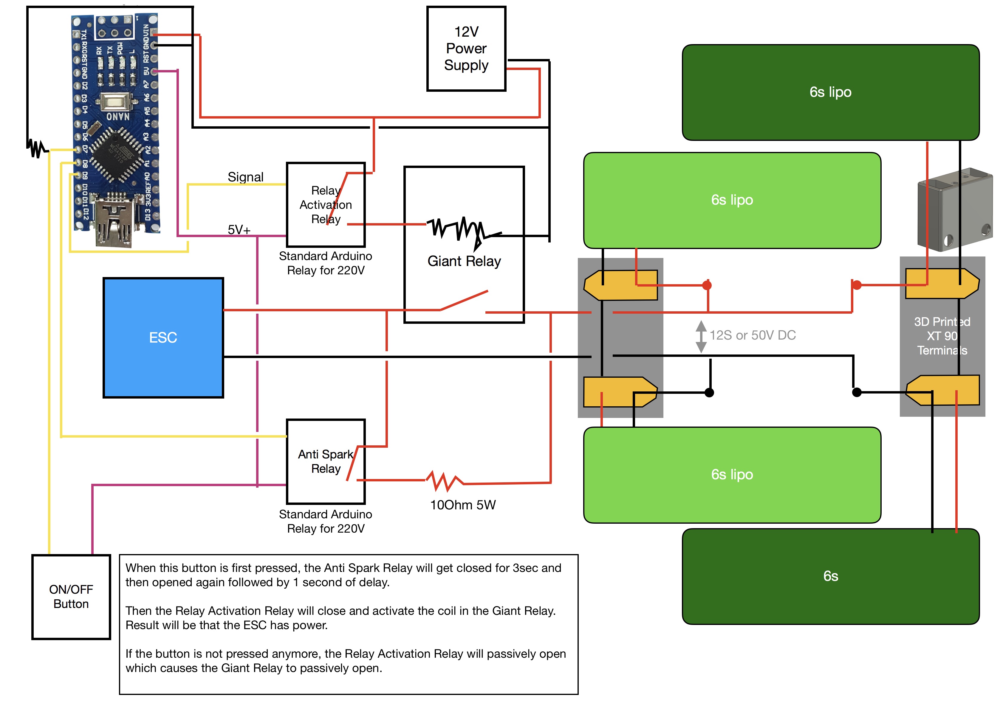
I have this big ass relay to cut off the lipos. It will get closed by a smaller relay which will be activated by an Arduino. The Arduino will first close a second small relay for anti spark and then disconnect it again after the big ass relay is closed.
The 2 extra relays are necessary because the Arduino cannot deliver enough power to close the big ass relay.
So the Arduino and the 3 relays need power first in order to power up the board.
The question is weather I should power the Arduino by the UBEC or a separate 12V battery. The thing with the UBEC would be that it is outside of the cutoff loop. So if the UBEC malfunctions, I cannot disable it.
Interesting question as I was thinking about this also. Powering by the UBEC should be fine, if it fails the Arduino will power down turning off outputs therefore opening the ‘bag ass relay’.?
I will power my microcontoller from the main battery like you describe. To switch off the battery completely i will use a reed switch that enables the ubec/buck converter. Diaabling the ubec will allow for zero power usage in the off state. I won‘t use as many relays in favor of electronic switching, but the concept is the same. Securing the ubec can be done with a fuse on the input, so on a malfunction the ubec will still be separated from the pack voltage. If you combine that with overvoltage protection diodes on the regulated side of your ubec, your electronics are safe, too. Switching your relay could also be achieved like this, also slightly more complicated it is not as bulky Pacificmeister Build Info and CAD Sources - #298 by Flo - Builds - FOIL.zone.
Question: if you power the Arduino and all the relay net thru the main batteries, what will be once you cut the main power? I guess Arduino goes out as well, or I miss part of the circuitry?
If it does, how do you engage antisparks and power back on again? Will you cut the power before of the ESC but after the UBEC? That could solve but then your safety just chop the power off the ESC no matter for the remote (unilely the Pacificmeister lanyard…), and a coil fully loaded like your huge motor, left to discharge onto the poor ESC mosfets ain’t a that safe, at all.
1st issue.
Second: 3 relays are something to deal with. I do know a bit of solenoids and those big Albright coils, they’re somewhat demanding, and thery’re coils, you need to protect your Arduino from those. Doable, no big deal, but does it drive your project toward complicated, does it?
Surely I’ll be wrong but in my idea, the Efoil main power needs a switch, to hisolate battery from everything, which is usefull on “everyday” basis an then eventually act as a “last safety before disaster”, eg. if your ESC blows… instead, to avoid potentially destructive switch off, riding safety should acts on motor power, read “ESC”, cutting the signal to have the motor come to a stop with no stress for other components. Arduino could help a lot in this too, that’s why lately I annoy @g.gregory8 on daily basis with my lousy codes.
I don’t know @MaxMaker, I would give a second thought to that relays switch…
Yes, the Big ass relay would only cut the power to the ESC not the UBEC. Alternatively, there won’t be an UBEC but a 12V block battery.
I did not know that cutting power to the ESC could cause problems for the ESC. There could be a sequence that first turns the throttle down and then cuts the main power all within one second. I don’t know though how long the delay would have to be.
I agree, i do not understand how cutting the power to the ESC would stress the ESC. It has big capacitors, so even if there is a small inductance from the battery cables to the ESC, it cannot rise the voltage at the capacitors to a destructive limit. The VESC has a supressor/zener/TVS diode at its DC-Link circuitry limiting the voltage.
I am using an albright relay together with a lanyard switch (the luxury version with 4 pins NO,NC) and i managed to mount it waterproof newly by using a small rubber ring to keep a larger rubber ring in position. The rubber rings are mounted on the inside of the housing.
The VESC has a BEC and supplies the receiver only. Parallel to the ESC i have a small BEC 12V to supply a pump or a blower. So if i pull the lanyard everything despite the Coloumeter and BMS is off. To switch the coloumeter off, i just pull the plug from the shunt pcb. I have to open the housing for charging anyhow.
Hopefully this proves true and cutting the power to the ESC under load doesn’t cause any damage (including the Seaking ESC). What about the inducted current from the motor while it winds down (acting as a generator), doesn’t this energy normally get dissipated back into the battery? Or just stored in the capacitors?
What is the power consumption of the albright relay to hold the contacts closed?
Also would you mind posting a link to the lanyard you used? I’m trying to find a supply of a good one, other than Amazon.
The VESC and others you can program to limit the generated voltage.
It would swing between generating and driving dependent on the input.
As the rider is not on board anymore if the lanyard is pulled, the driving and controlling mass is not present any more, so the foil might glide, jump or just stop. The prop is rotated by the water randomly and can generate a voltage into the DC-Link circuit. There should be a zener diode. However,
What can the ESC do? If it still gets a valid signal for high throttle, it will sink the voltage out of the DC-Link within ms and go to Undervoltage, maybe reset, and so forth. It gets complex. Although i think, the motor is not able to produce Overvoltage in a passive B6 mosfet circuit. Maybe if you are towed or in big waves.
Better to use this switch under controlled conditions, with no motor driving, i agree. Better apply a braking command to the ESC, e.g. by cutting the signal. But also this comes maybe too late, if it takes 2 seconds.
So lets work on a safe remote control. A dial wheel, and a trigger switch, similar in function to my jigsaw. As long as you press the trigger, the motor will accelarate, in a moderate way to the given power or RPM or whatever given by the dial wheel which needs no attention by the rider. If you find you should drive faster, use your thumb to turn the cogged wheel a few teeth forward and a higher speed will be the result. If you want you can use this cogged wheel for dynamic maneuvers. The normal way to start the board would be a defined ramp up of power to a given end value, by just dialing in the wanted value and press the trigger. Whenever you release the trigger, the ESC goes to brake mode, but moderate.
I too like the triggers of cordless drilles. They are a better design like the gun trigger style I have seen here.
So you say the VESC will be alright? I am not sure if I should enable or disable breaking regeneration. (This is what you have been referring to right?)
Vesc will be definitely the way to go, as soon as max power/overheating issues would be solved, anyway, regenerative function can’t exist if a solenoid cut the battery connection!
Trigger drillbit style it’s a great idea, with a very reliable remote
It could work! Small relays protects the electronics. Basically, the first stage relay works as capacitors “precharge”? Let’s see how it goes. I wish to test the Vedder antispark soon, so we can compare these solutions.
I just tested the relay. I run it at 9.5V even though it is a 12V relay. I measured 1A of current. Unfortunatley, it reached about 90°C after about 10min. That is not acceptable. Any ideas what I could do? Would 12 or 15V help?
 with my lousy codes.