No problem, here is a public link to the FUSION360 design.
the same propulsion unit is still being used, been riding it a lot. At least 30 times. No leaks, shaft coupler still working. the disadvantage is that you can’t disassemble it to change motor/gearbox without sawing up the tube and gluing it back together. We did that when the first gearbox got stripped.
if you are having problems editing to fit the profile I can help you out. if you have the naish profile.
also the design can easily be edited to fit 60mmOD 56mmID tube. It fits tighter around the SSSmotor.
Thankyou @Hiorth That really helps me out. I am brand new to fusion, but I’m going to give it my best shot. Does this mast clamp fit 8awg cables easily or would I need to mod that too. I have the 60mm X 57 mm tubing in transit, so I shouldn’t need any modifications for that. I was looking at trying to design the mast end with a flange to dismantle, but I think it would end up to bulky and cause drag.
Thanks again for your help. You guys are legends.
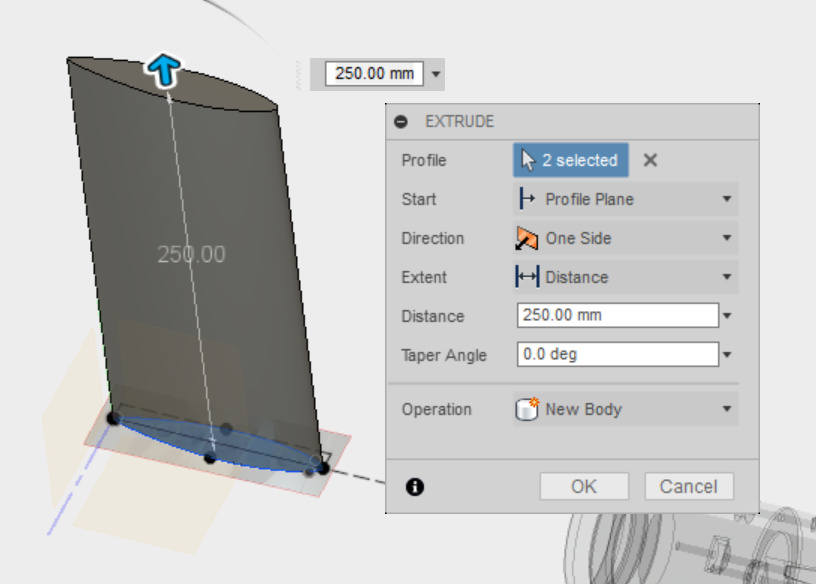
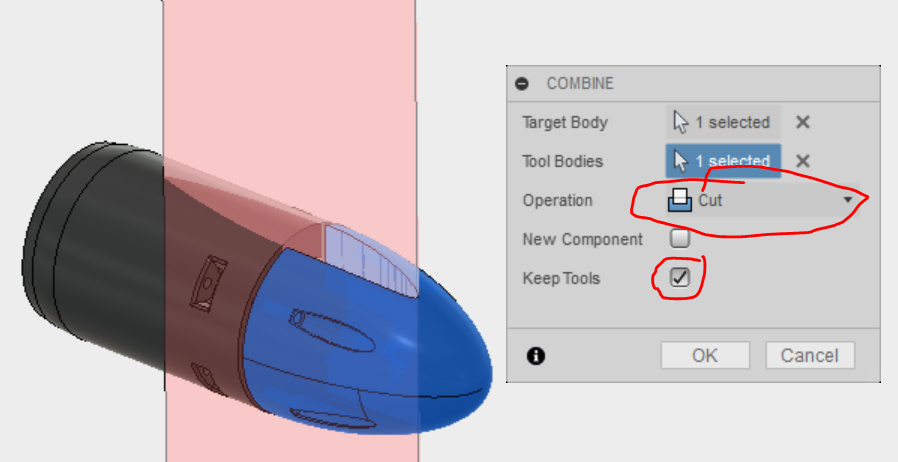
I spent most of the day trying to get the mast profile sorted. I was able to upload the mast profile picture into fusion 360, make a sketch, extrude it and move it ito position, but I can’t for some reason cut into the original drawing. Also, I’m not sure that I’m using the correct tool to draw the lines, they look a bit wonky. I think I may need to take you up on your offer to help please @Hiorth
Here’s the link to what I’ve done so far. https://a360.co/2JwJ42T I’ll also upload the mast profile picture too. I appreciate everything you’ve done.
Did you use the spline tool? It looks like you just connected the points with straight lines…
The spline tool makes a line 3rd order, so no edges and smooth connection of (end-)points.
Thanks again for your help. The mast profile measurement is 99mm x 9.5mm (19mm when mirrored). I was drawing with 3 x 3 point arcs. I didn’t think it was right. I am brand new to fusion, but hopefully with some practice I’ll get the hang of it.
Thankyou Brent. I’m currently rebuilding the motor pod after my initial hick up. I hope to have it flying on the Great Barrier Reef within a couple weeks. I’ll upload a video here when it happens.
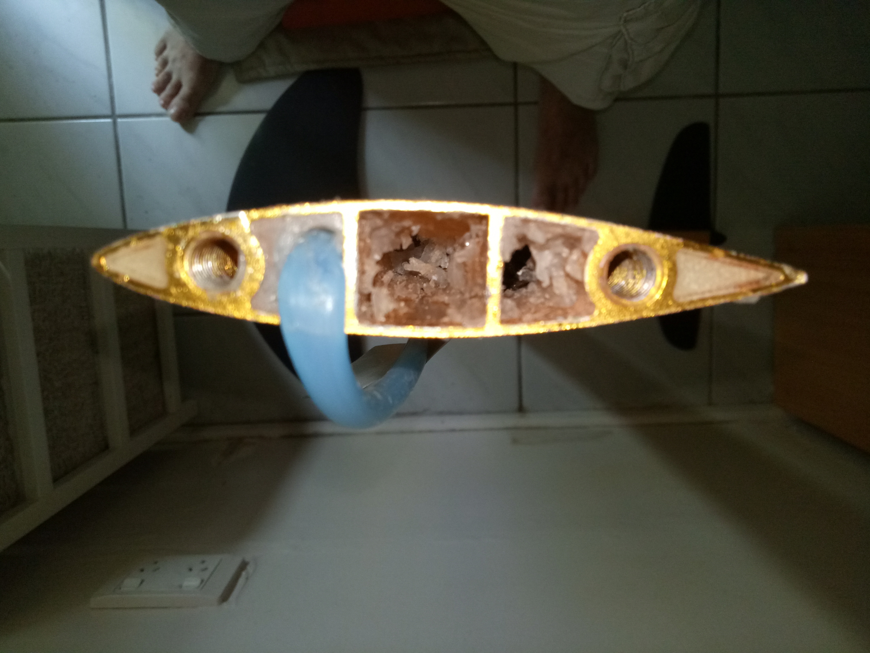
I finally got the new mast clamp printed. Thankyou @Hiorth for all of your help. I would have struggled without you. I drilled and tapped threads to fit ip68 cable glands into the mount. I also filled the bottom of the mast mount with a layer of epoxy to eliminate any chance of water leaking through the threads.
I tested the motor prior to installing it in the pod and it has twitches at full throttle. The motor has possibly been damaged when salt water entered the pod on my first attempt. I have ordered a new motor, so hopefully this is the problem. Also the gearbox heated up at the front. I think this could have been due to incorrect alignment of the motor gearbox mount. Building this efoil has been a long road for me, but hopefully determination will get me through.
Hi rogjalon all good it was to good to be true.
PS: What size cable glad & what size cable are you using? the “new mast clamp” looks great well done.
Al
My cable size is 8awg.
Are you building the Hiorth V1 build? To tighten cable glands on the inside like this, you need to be using a design where the design allows the gearbox to be secured to the gearbox mount after the mast mount is glued in place.
Hi Rogjalon, .
Regarding your question “Are you building the Hiorth V1 build” I have to answer no. I am building a design based on both the Hiorth brothers & pacificmeister designs.
As I currently have only a metal lathe & not a 3D printer I have redesigned the couplings & both end caps to be machined from aluminium & solid nylon (Autodesk Inventor). I am using a 4:1 Neugart & 500KV motor (that to arrive today) . would of liked a 5:1 but just could not find one.
I am considering a mechanical seal & lipseal combo as per image below with a metal heat sink around the gearbox. (I am Not happy with my design overall size so will keep working on it before I build)
Relay not sure about what pitch propeller I will start with, But that is a issue I will look at once I have the rest of the hardware sorted. I will also be reducing the size of a few of my components now that I have seen the brilliant designs of both Hiorth brothers & pacificmeister as well as reading heaps of stuff on efoil.design
Thank you for your input as well. I will need to ask more questions again soon.
I think Nemo is amazing!
Looks great Al. I think the machined parts are always going to be stronger and more waterproof than the 3D printed parts too. I think having a heat sink around the gearbox is a great idea. It was my plan to do this, but without machinery it’s difficult to do. I think both Pacific Meister and Hiorth designs are excellent. Using a prop from either one of these designs should work fine.
Nemo isn’t perfect yet. My skills are limited. Like many, I’m learning a lot as I go. But I’m happy to answer any questions and help where I can.
I still need to shorten the length but all parts are metal designed for lathe & drill press manufacture , I also would like to transfer the torque off the gearbox & back onto the motor mount via the gearbox heat sink. (WIP)
Ditched the mechanical seal for x2 lip seal. but will need to obtain a higher quality surface finish on propeller shaft at lip seal location. if i keep the step that transfers the thrust via the coupling to the thrust bearing.
@rogjalon Good question,
What I have done is include a step so thrust from the prop shaft will always pass through the coupling between motor & gearbox onto the trust bearing even if a grub screw comes lose . this way it will never apply load directly onto the gearbox shaft …applying to much load onto gearbox bearings which would be a bad thing.