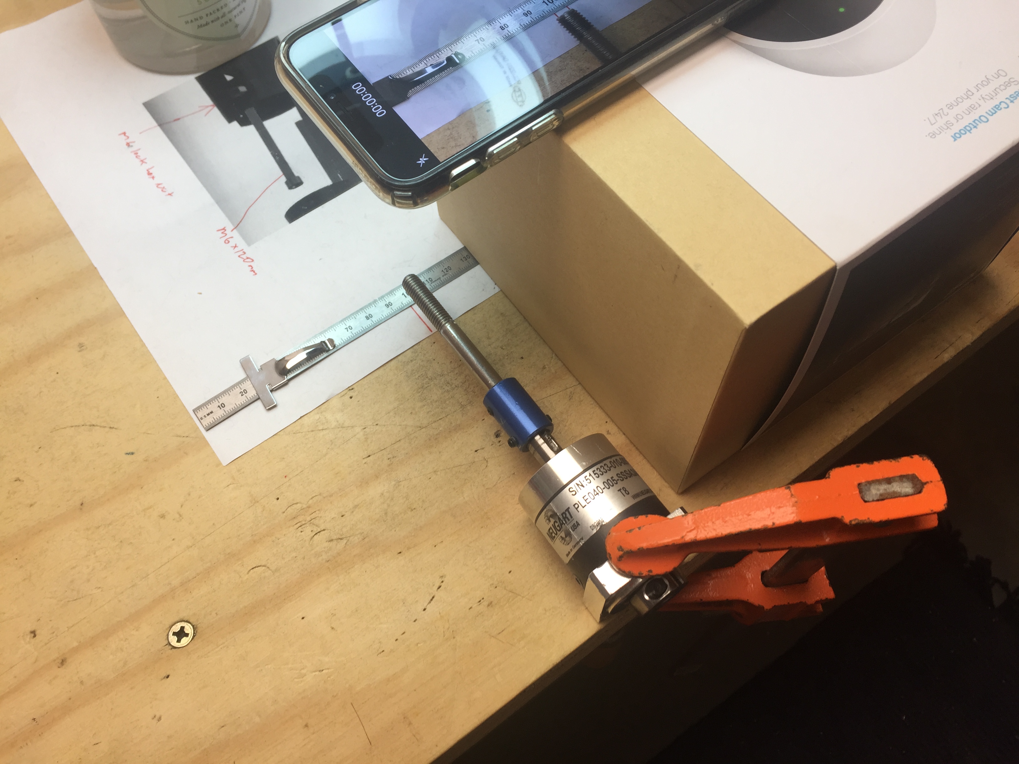
I know how critical prop shaft alignment is when using a coupler from the many posts of others that had leaks due to a wobbling shaft. So how best to do it? When the prop shaft is mounted to the gearbox with a coupler and powered by the motor it spins too fast to see exactly in which direction to make any adjustments. So it must be done with the gearbox disconnected from the motor and turned by hand. Recording this on a smart phone with a couple of reference lines and a mark on the shaft makes the whole process even easier. Then it’s just a matter of fiddling with the set screws until she spins true. Set-up photo and resulting video below.
3 Likes
I’m not sure if this is enough to make sure there is no wobble in the end of the shaft because it still depends on the position of the bearing when everything is assembled, so it also depends on the roundness of the tube and accuracy of the part holding the bearing. My idea on checking if the shaft is running true is to put gear and shaft into the tube and attach a 8mm shaft that sticks out of the tube on the motor side. I would then move the shaft by hand and check the shaft on the propeller side with a dial indicator gauge. The question is what is acceptable? ±0.05mm? The shaft itself also has tolerances on how straight it is, should be quit good though, something like ±0.01mm/10cm or better. Has anyone measured concentricity of the shaft?
I think it all starts with having a shaft coupler and shaft extension that are spinning true and perfectly aligned with the gear shaft. And then – yes – the sealmount bearing must be properly positioned to accept that shaft. But is is far easier to make adjustments to the coupler while the sealmount is not in place.
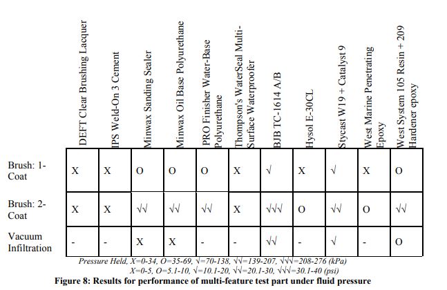
Interesting technical paper on the best way to waterproof 3d printed parts. The chart below shows how much pressure each ABS printed part was able to withstand in kPa and psi based on the application technique and the treatment product used. For example two brushed-on coats of Minwax polyurethane was able to withstand 20 psi.
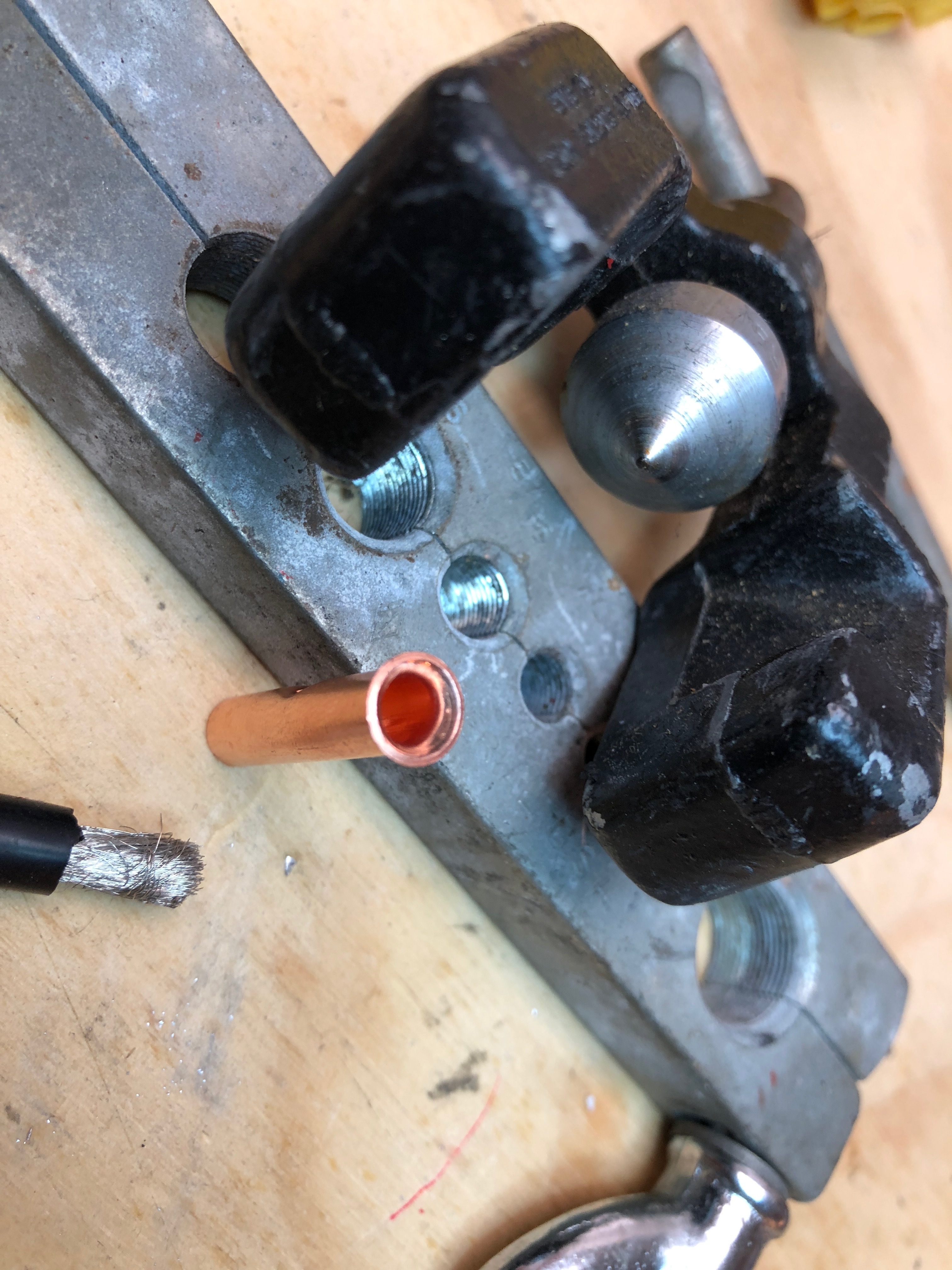
Getting an 8 gauge wire to go into these 8 gauge copper crimp butt connectors is no easy task. Inevitably some of the wire strands get pushed outside. I have found using a flaring tool beforehand makes the task far easier. A slight flare at each end makes the wires funnel into place perfectly.
1 Like
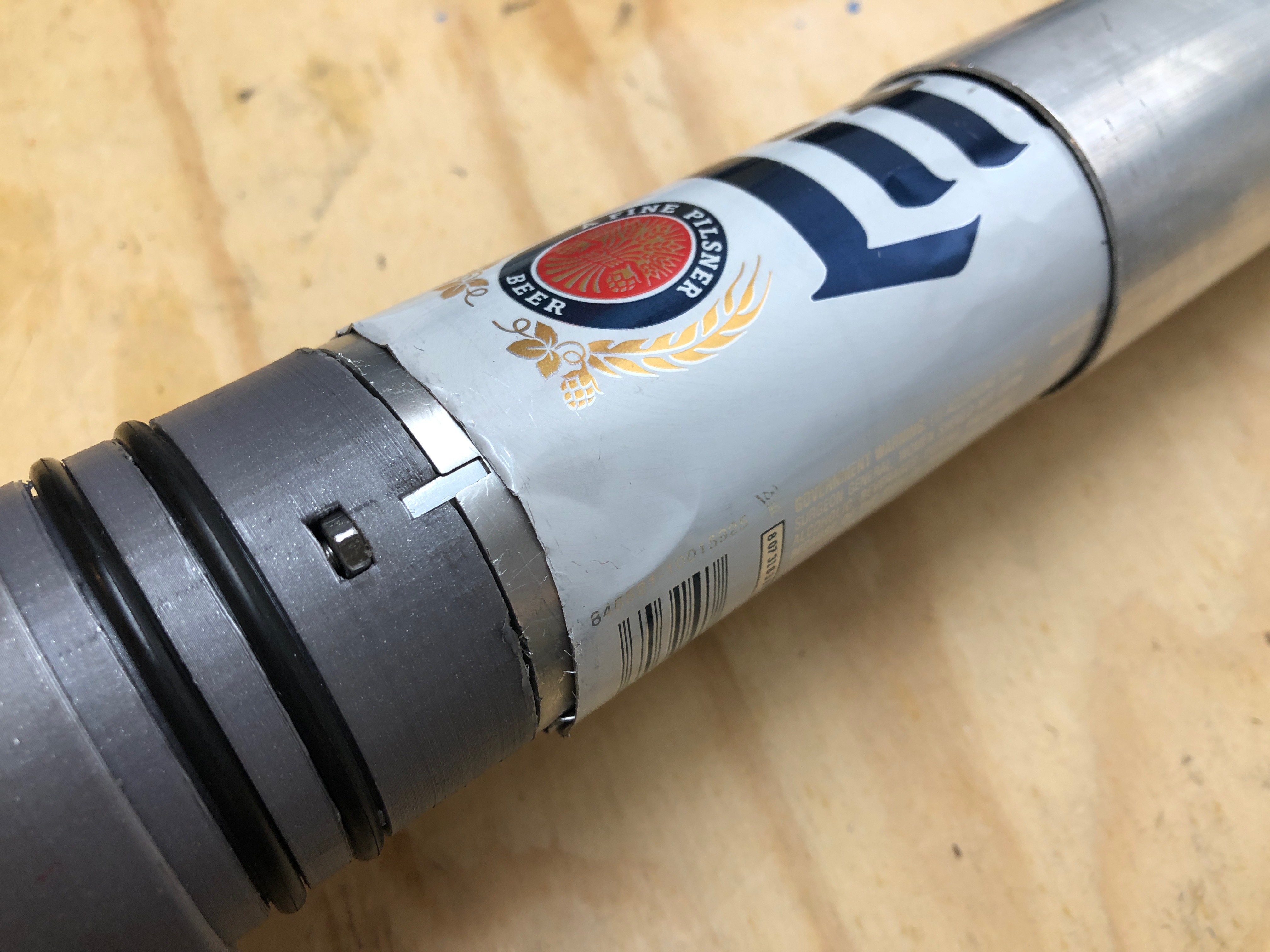
Those of us undertaking the PacificMeister build have to contend with the tiny gap between the motor and the very slightly larger outer tube housing into which the motor slides. These walls need to touch to keep the motor running as cool as possible. Rather than relying solely on heat paste to fill this gap I have found that the metal from a Miller Lite beer bottle fits just about perfectly. Be super careful cutting the bottle as the metal is extremely sharp. I may still use a thin coating of heat paste to ensure a really tight fit.

4 Likes
Another good alternative is 0.3mm silicone heat pads to transfer the heat.
Isn’t that an insulator?
Electrically yes, but they are designed to transfer heat between chips and heatsinks, much like thermal paste.
1 Like
Nice love the use of material! We did something similiar, but used aluminium tape instead.
1 Like
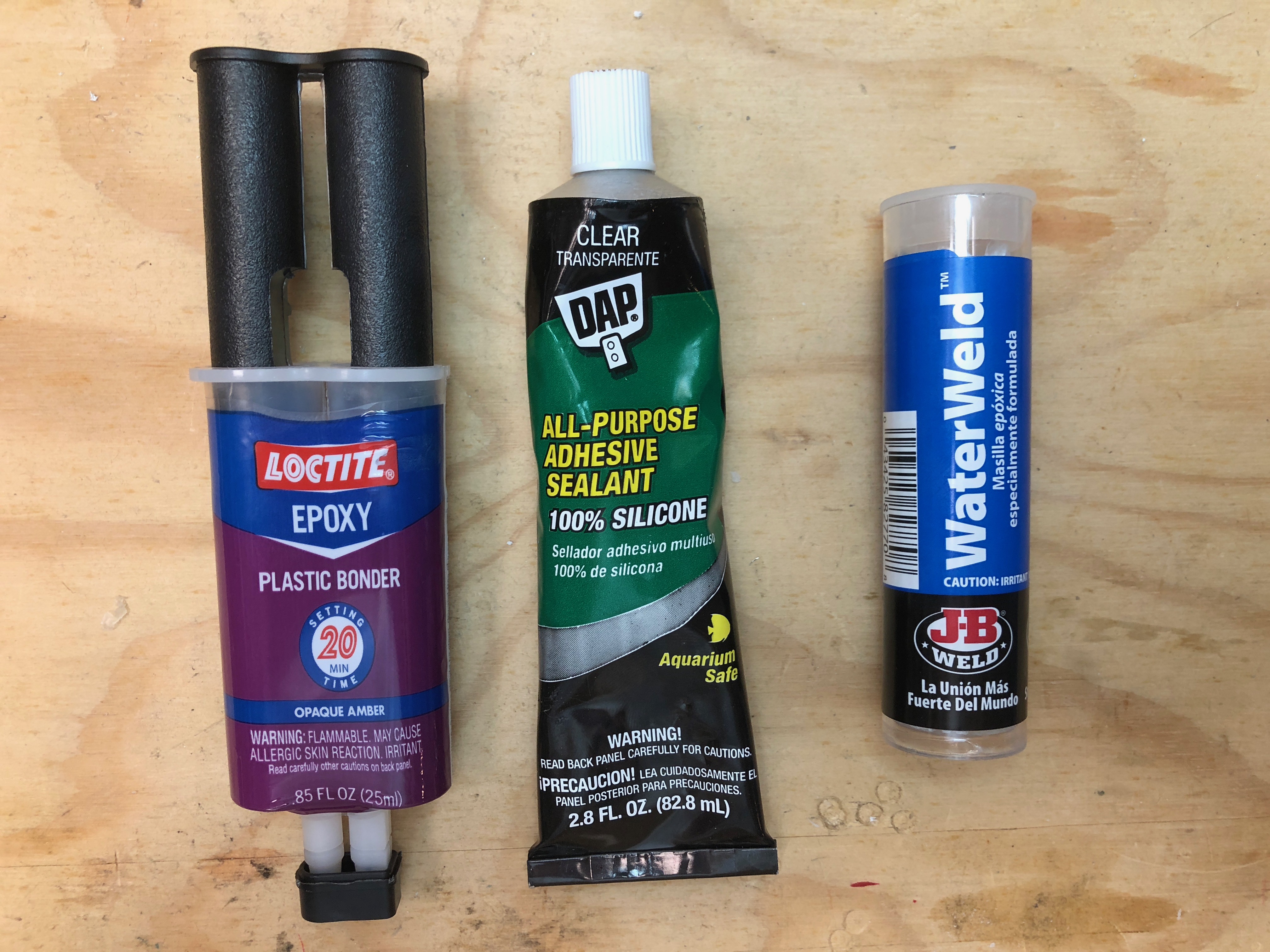
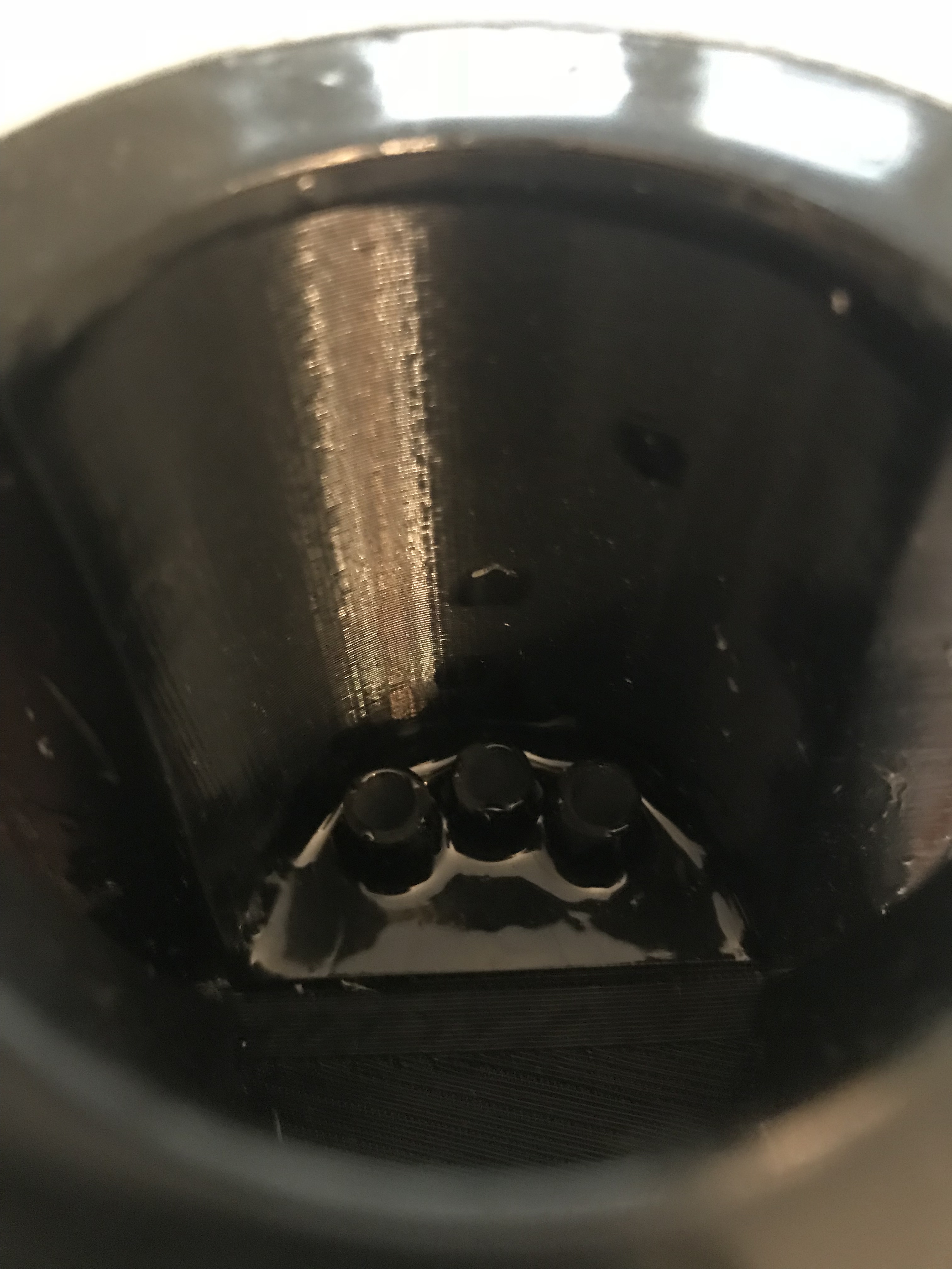
I have tested several substances to seal the wires as they pass through the rear mast clamp. This is a critical step because it’s the only thing keeping water out of the “engine room.” After the substance dries there will be a fair amount of flex on the wires (and the surrounding filler) as the clamp is pressed into position so it cannot crack or peel under stress. So far I like the silicone best since it adheres well and also flexes without failing.
Here’s what the silicone looks like on a test piece: https://youtu.be/GnUwgPrngyE
Any other suggestions are welcome!
I userd marine silicone from Bostik. What I also do is to epoxy a 15mm carbon pipe for each cable. The carbon pipe has a very tight fit to the cable.
3 Likes
Among the nice things of this solution:
- excellent thermal conduction
- cheap, cut with scissors, not sharp
- easily available in the local DiY shops (insulation)
- you can tune the fit depending on the number of tape layers, a tapered fit with a step cut…

- durable but not permanent if need be
- …
The glue is supposed to be temperature resistant (150 to 300 deg C) but the glue water resistance status is not guaranteed so if 2 stuck pieces can stay for a few hours in a water glass (fresh and salt) it’s even better.
1 Like
I considered metal tape but was concerned the adhesive might provide some level of insulation.
It’s a trade off:) still like your approach better, using regular household stuff.
I had the same thought. What if you would wrap common household aluminium foil super tight around the motor? This has no glue and with a good fit it should not unwrap
See my post , i went from 40mm to 45 then to 50 for the motor and the gearbox : 38mm to 40 with tape then to 50 with tubing
As i understand it multiple layers of tinfoil can trap a slight amount of air between them which will act as an insulator. Thus the snugger the fit the better from a heat conductivity standpoint so you might find the foil tears when you try to press the motor into the tube.
I did something similar to create a mechanically tight fit for the three wires as they pass thru the rear mast clamp before adding a waterproofing substance. I placed the little rubber rings from THESE PG7 cable glands around each of the three wires and forced that into each hole for a very tight fit.
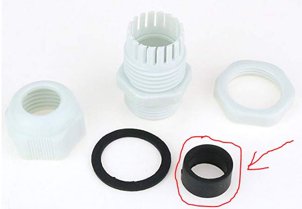
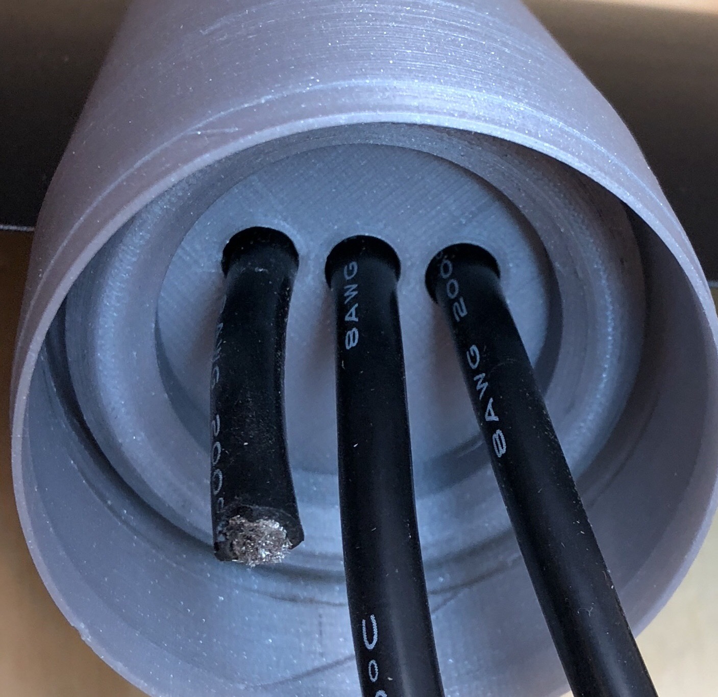
2 Likes
Indeed, the air is the problem. So it is quite important not to trap any air when applying the tape, getting some kind mini bubbles of air sealed by the glue.