I’m hoping someone can advise on this please. Its been suggested to extend the receiver antenna outside of an aluminium enclosure to improve reception.
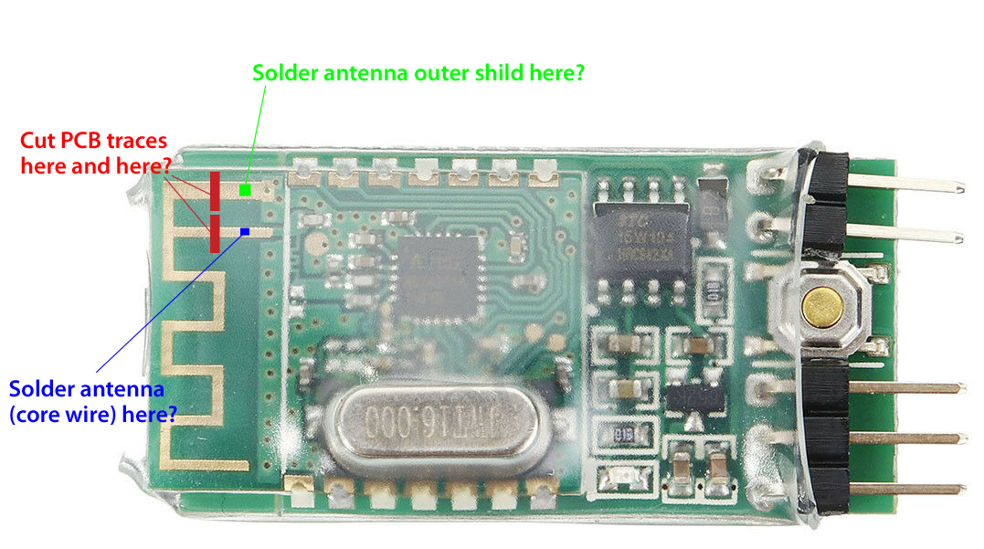
I think I’m on the right lines but before I destroy my receiver I thought I’d ask here. Does the below cut and solder points look correct?
The part I’m not sure on is the ground and antenna seem to be on the joined, but its a bit beyond my understanding tbh?
Difficult to see from the picture but to me it looks like you would only have to solder the core of the external antenna cable to either of the points (as they are connected) in your picture (blue or green) because the “rectangular” trace represents the antenna, the shield needs to be connected to ground.
Not exactly the same receiver but as an inspiration: https://www.stall.biz/project/esp8266-esp12-mit-externer-wlan-antenne-fuer-wiffi-und-co
This is where I’m not sure. The PCB trace shown by Green in the above image seems to be connected to the ground plate on the reverse of the board.
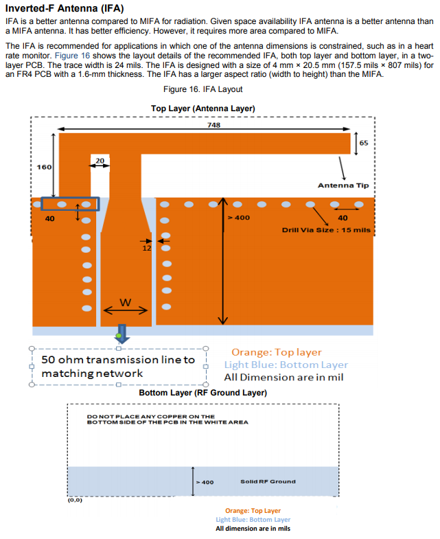
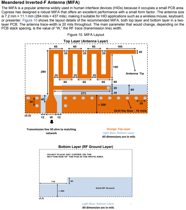
I’ve found a few antenna design documents, the easiest to understand being this one, and the seem to support that the additional PCB trace goes to ground to alter the radiation patterns of the antenna, directing it in certain directions
PDF: https://www.cypress.com/file/136236/download
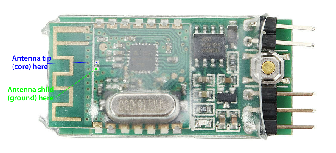
They suggest when hooking up a PCB antenna to tuning equipment,
Connect the coax tip to the pad closest to the chip. And there should be an exposed ground pad close to the tip. The shorter the distance the better.
The receiver does seem to have these pads. So I’m thinking connect as per below and test it out without cutting any traces.