I used the same one ( be carefull the quality Ones are not in plastic but “Bakélite”) in between my 4s pack to get 8s when switch on , worked well all last summer ,got the 200a , will still use it this year , but it gets a bit warm/hot after a long run
That is a way to keep the 6+6 for charging but 2 plugs will be left alone when running i didn’t like this idea …
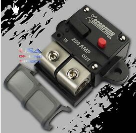
Last year I used this one. I am no longer using it. These are my observations. Many people on this forum are using it. It takes up too much space to fit in my enclosure. Never tripped even when I got in weeds which caused me to destroy my 200 AMP ESC. The XT90 connectors on my pair of multistar 20Ahr batteries started to melt first. I read somewhere that you need to go over 150 AMPs for quite while for it to trip. It works fine for a ON/OFF switch with no additional anti spark. Feels and looks high quality.
I only expect this to work for catastrophic failures (dead shorts) but this is good to know - the one I got is unlikely to ever trip. When it gets here I’ll check the size and see if I can use it at all, then swap it for a smaller one.
If I blow up my driver I’ll probably replace it with a VESC6 since it’s a lot more configurable. However it tops out at 100A. Come to think of it I better start logging current draw (scope creep!).
Maybe consider some of the designs based on the Vesc6 that run the same firmware if you choose to go this route. I only have experience with my diy vesc, but there are several to choose if you search the electric skateboard designs. E.g. A200S, there are also some ready to purchase with similar price.
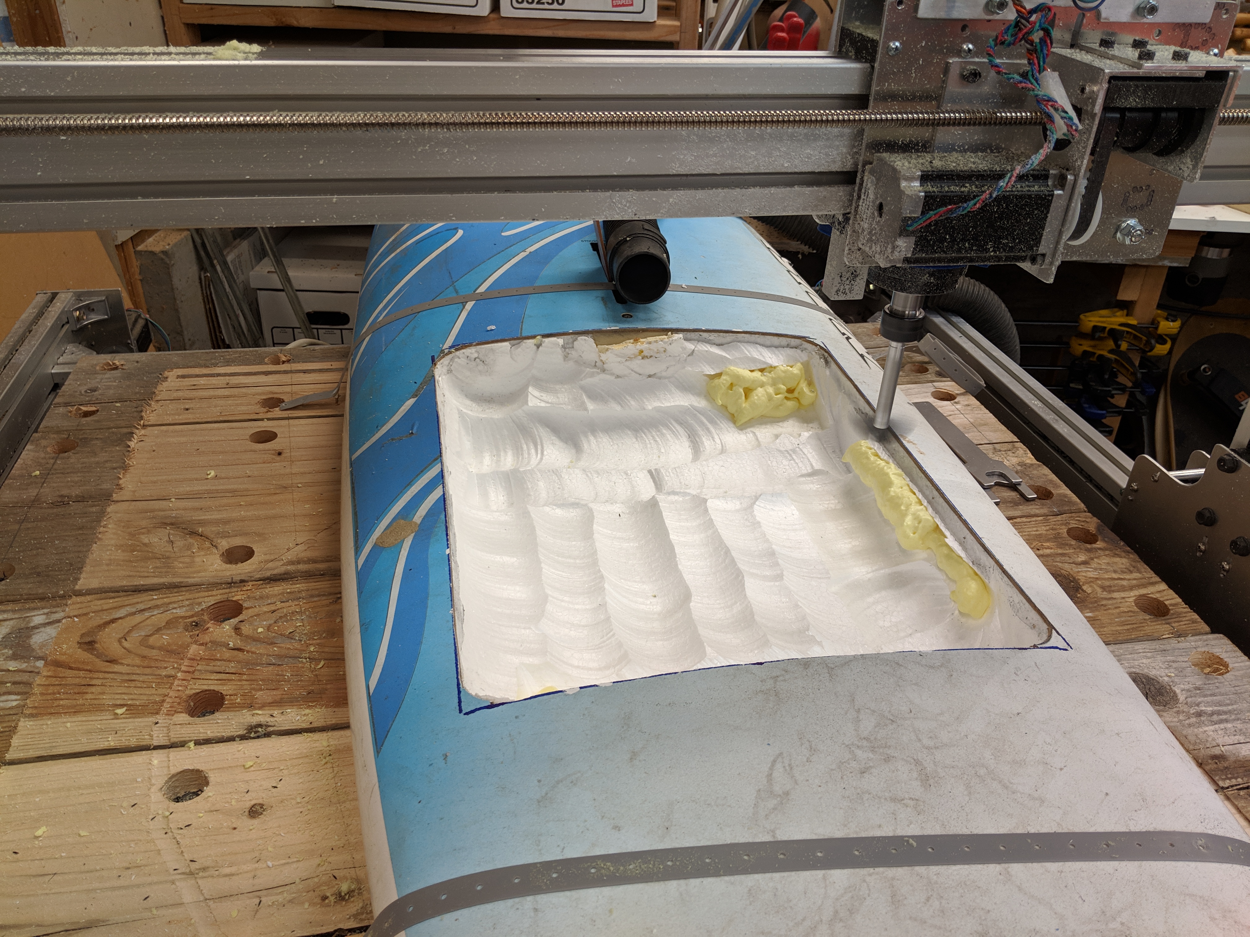
I did learn the wisdom of rough cutting vs. fine cutting. My original plan was 0.2" depth cuts with 0.3" stepover. If I had done that the thing would still be cutting. I roughed it out with 1" stepover and then went back and did a 0.3 stepover final.
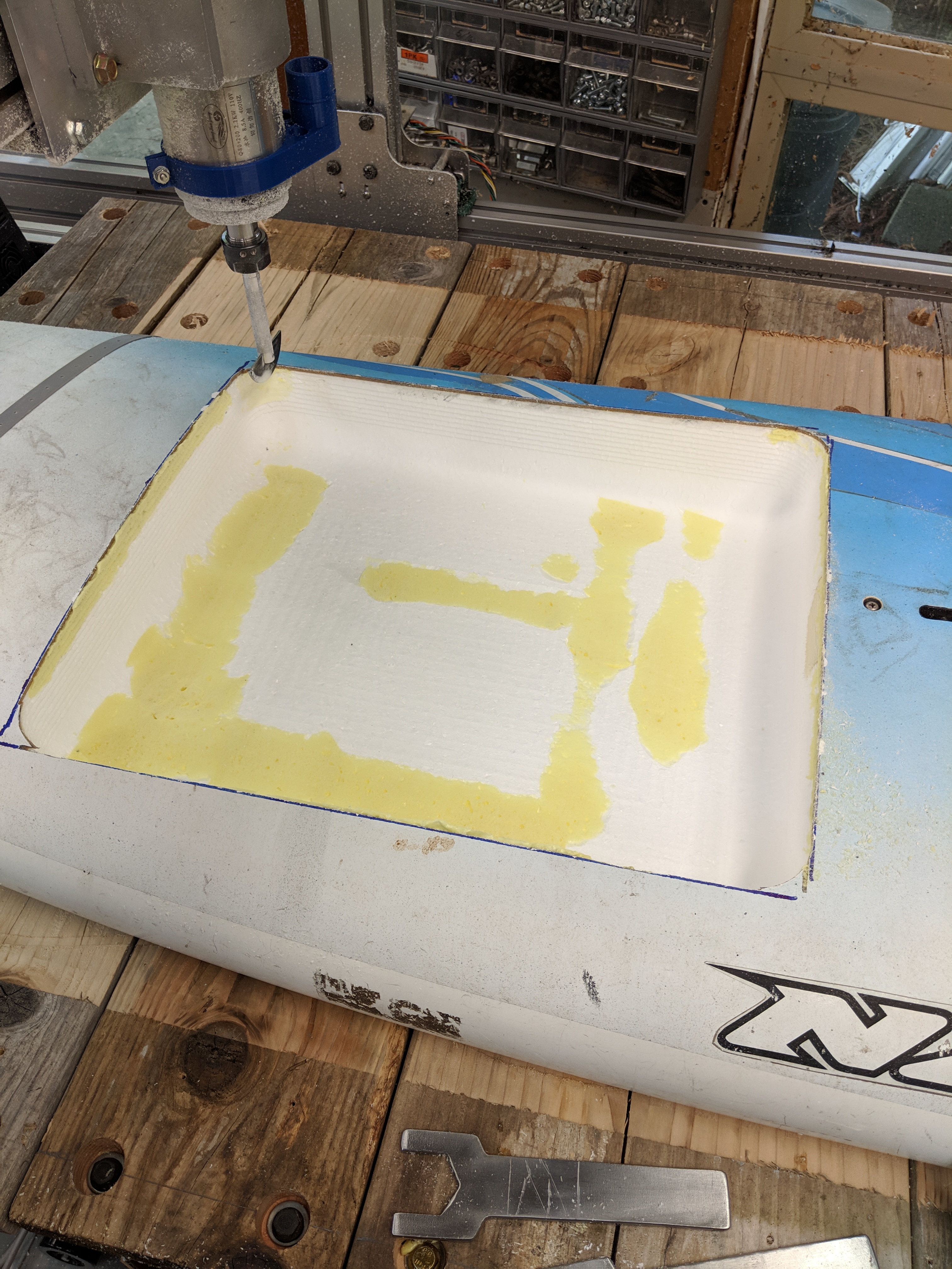
I just need to router around the outside edges to give myself a roundover, then drill some drain holes and start drilling sideways to run lines between the battery box and the power box and the mast. So I guess the next step is to place the mast mount.
Then fiberglass these two openings in.
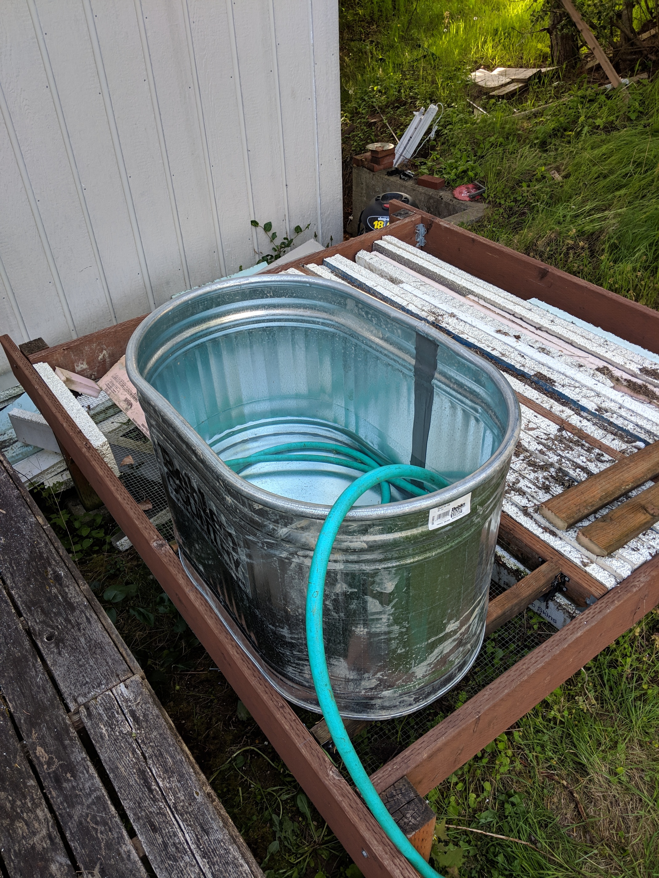
I liked @MAC’s idea of getting a big water trough for testing. I was originally going to just take it down to the lake and go for it, but I can see the wisdom of doing some actual load testing before committing to a large body of water.
on top of looking at the amp, the voltage you’re using and the quality of your connection will matter a lot:
i started using that:
but it kept tripping, and to turn it back on you have to open the board on the water… and if you let a few drops in at the wrong place, you coulomb meter will literally take on fire…
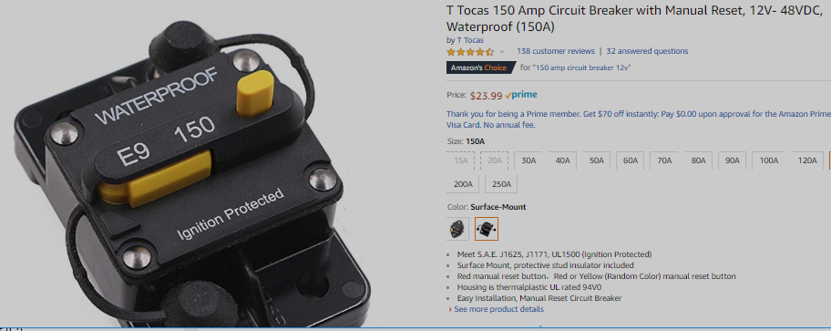
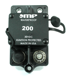
now i’m using:
171-S1-200-2
and not a single issue, and even if it trips, it should auto-reset.
The difference was that the first one was rated for 12V and the second one is for 48V.
On top of that, it was much harder to get good connection for the wires in the first one, and i’m guessing the reduced area of contact made it heat even more.
I think in the end, it was never tripping due to high current, only due to heating up too much…
On the second one, you just solder ring terminal and the connection is much better.
Same here. The nuts need to be very tight or it will heat up a lot. I could smell the heat coming off the nut on my relay. Just had to touch it anyways. My finger made a sss noise.
A bit of forward movement, I got the edges of the cutouts rounded over and sanded down to the fiberglass around them. I figured out how I’m going to route the wires from one place to another, and I made the mount plate for the mast.
The platform it’s sitting on was originally going to hold a hot tub, but that project did not make it past the “clear cedar is how much?” phase.
Next week I’m going to carve out the holes the wires run through, and actually put the motor assembly in the tub and spin it up. This assumes that the battery box somehow magically assembles itself between now and then.
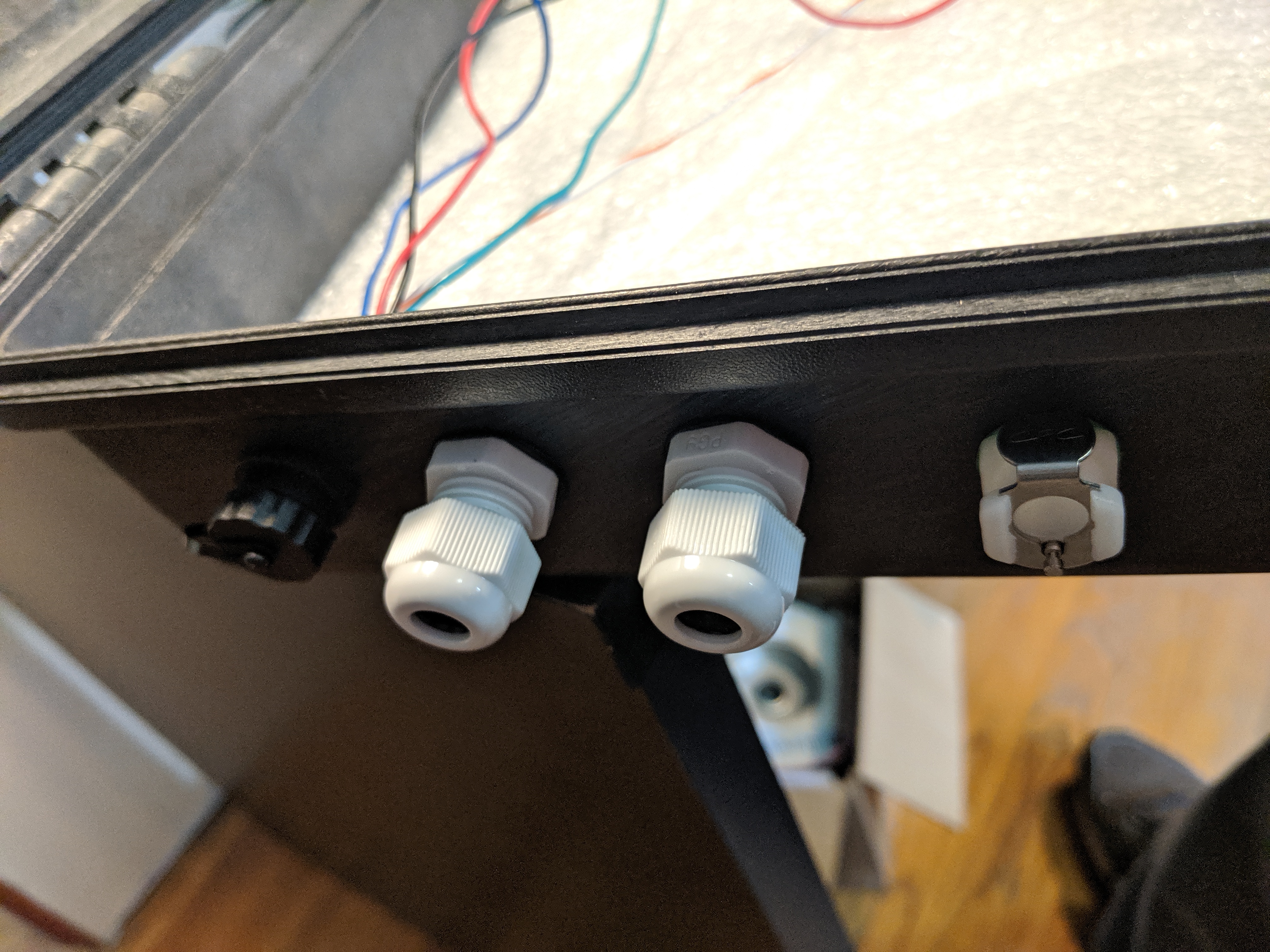
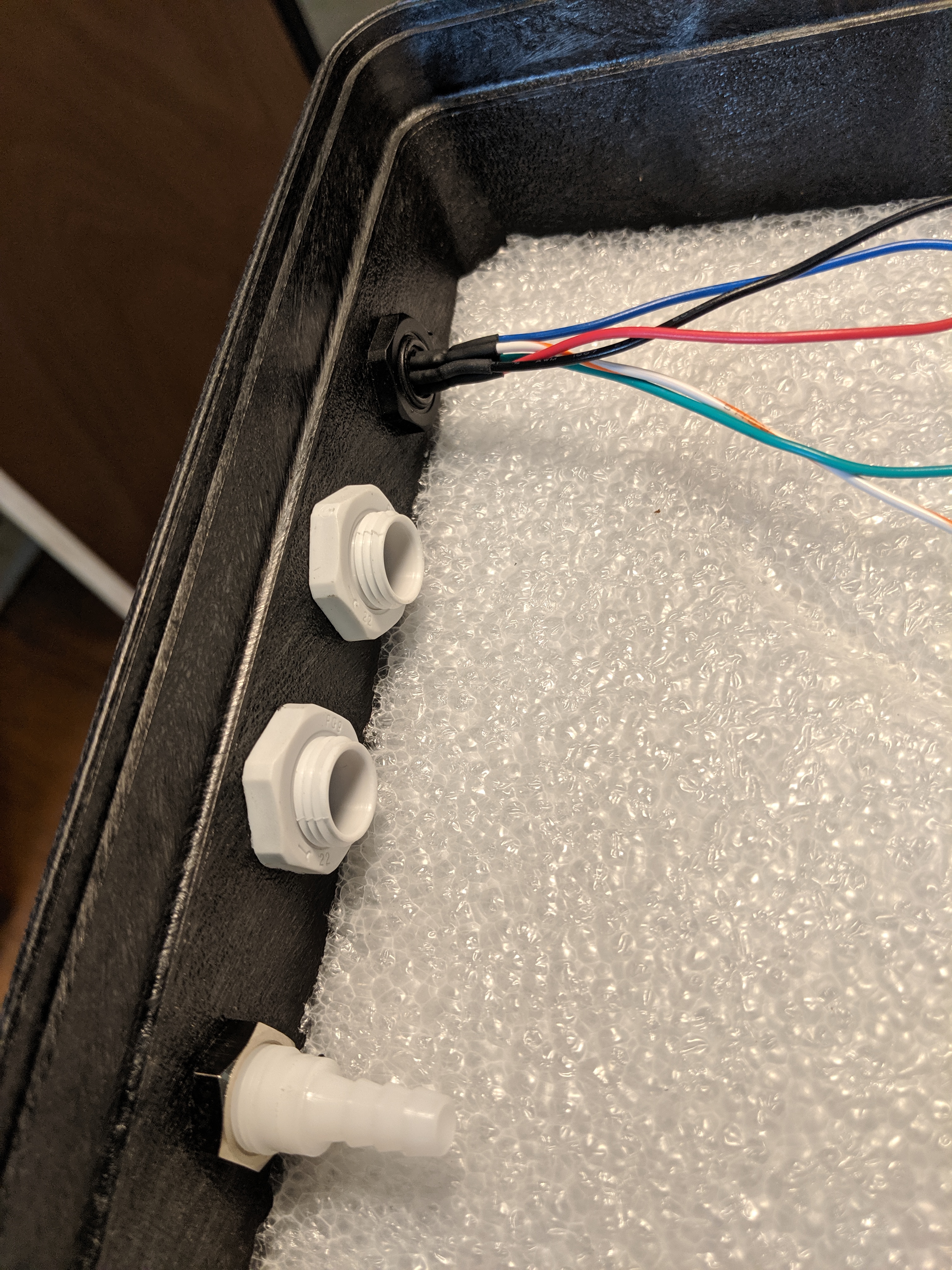
The extra deep cable glands took a while to find, but finally I found them at Digi-Key, which I guess I should have looked at first.
The ones in the pictures are IPG-22294-G (DK 377-2210-ND)
So the battery box should be fully assembled by the end of the weekend. Then it’s time to epoxy the mast mount plate to the board. Hopefully it’ll be sunny enough tomorrow so it will cure properly.
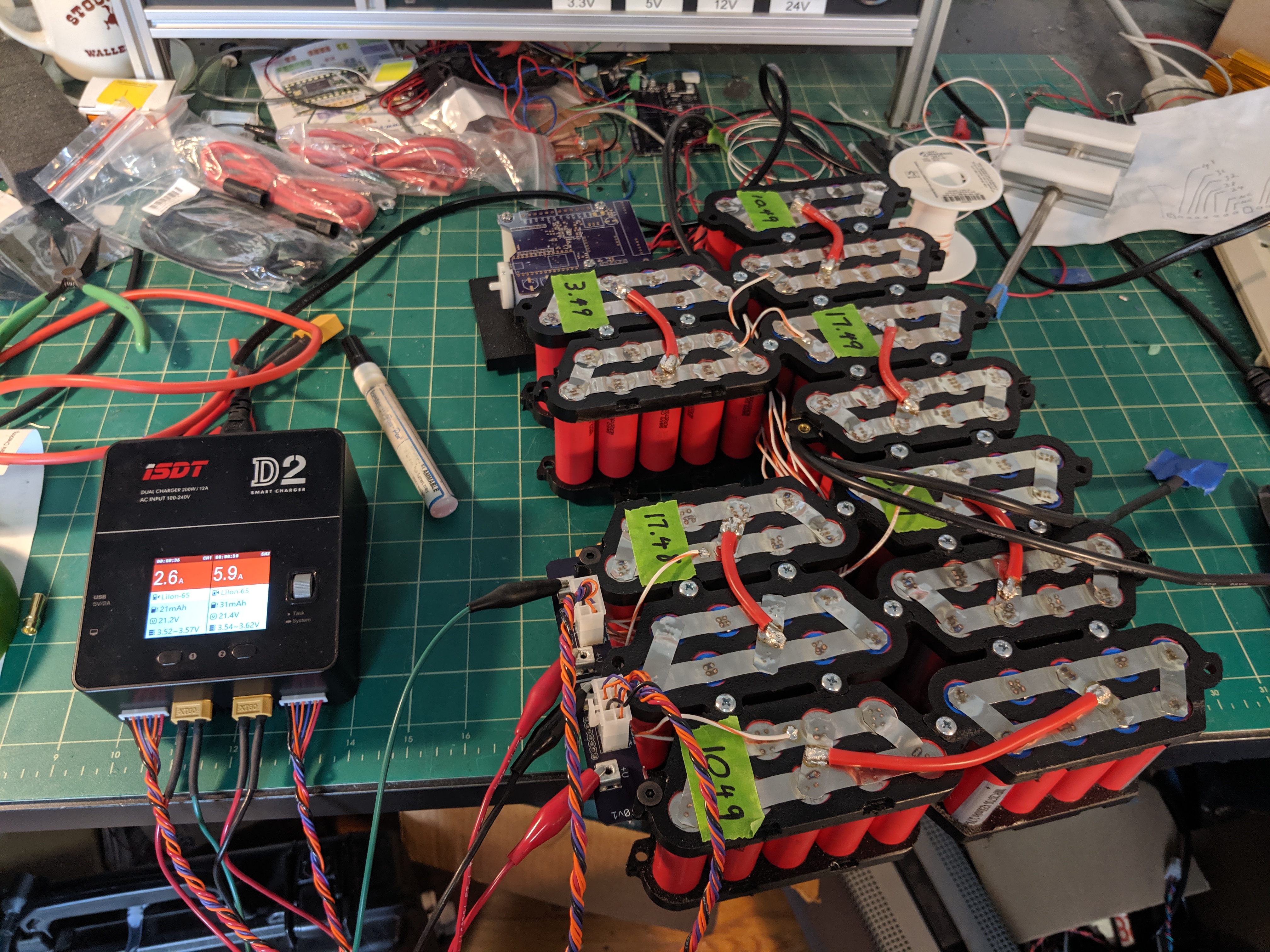
Welcome back. Looks good. Are you balance charging or using a BMS. My battery is behind schedule. I still need to work out some details. Hoping to make some progress this week.
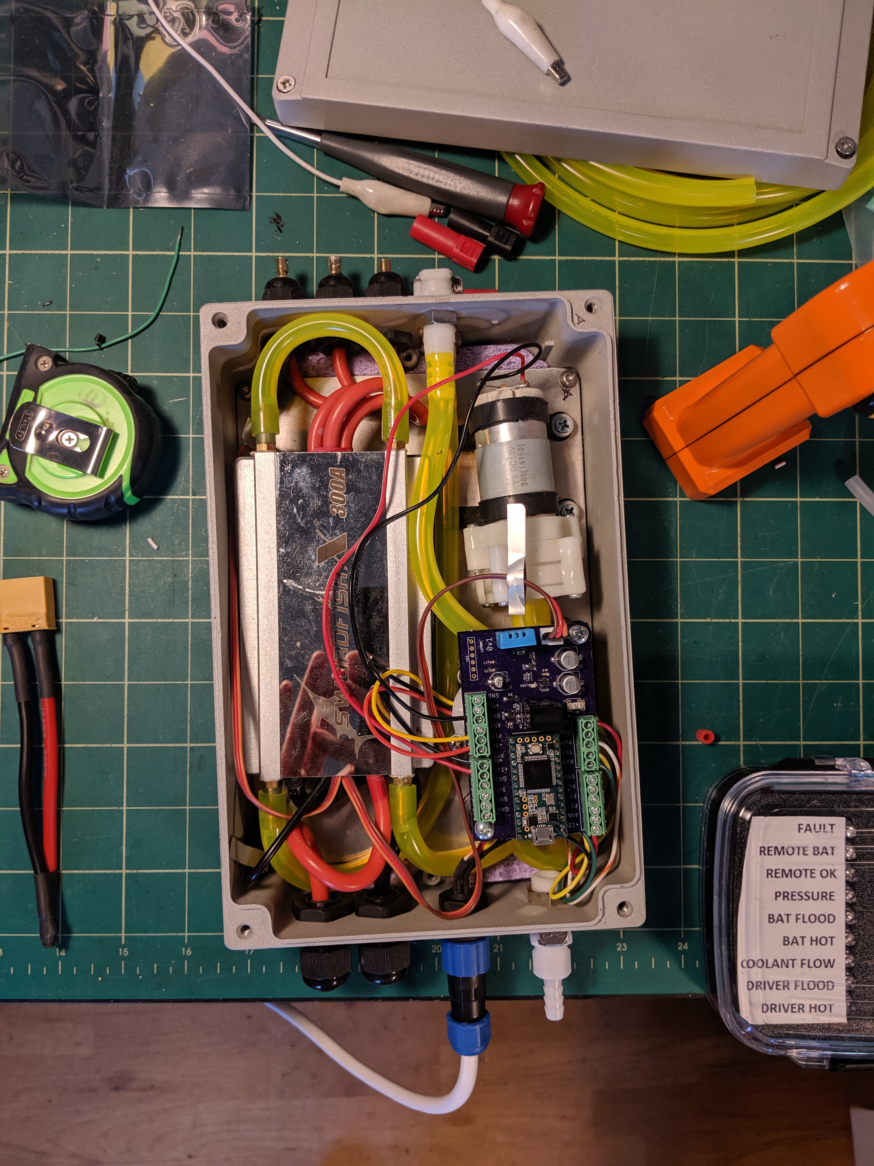
but I had to split it to get it to work with the dual charger. If there is any connection at all between the 2 sides the charger safety’s out, so I have to have a disconnect between the 2 halves (handy place to put a fuse, though right now I just have an XT90, which you can see in the lower left of the picture.
I got the mast mount plate epoxied to the board last weekend and this coming long weekend I’ve managed to allocate a whole day to fiberglassing the 2 insets in the board where the battery box and driver box go.
So in theory I should have a fully complete board in another week ready for tank testing!
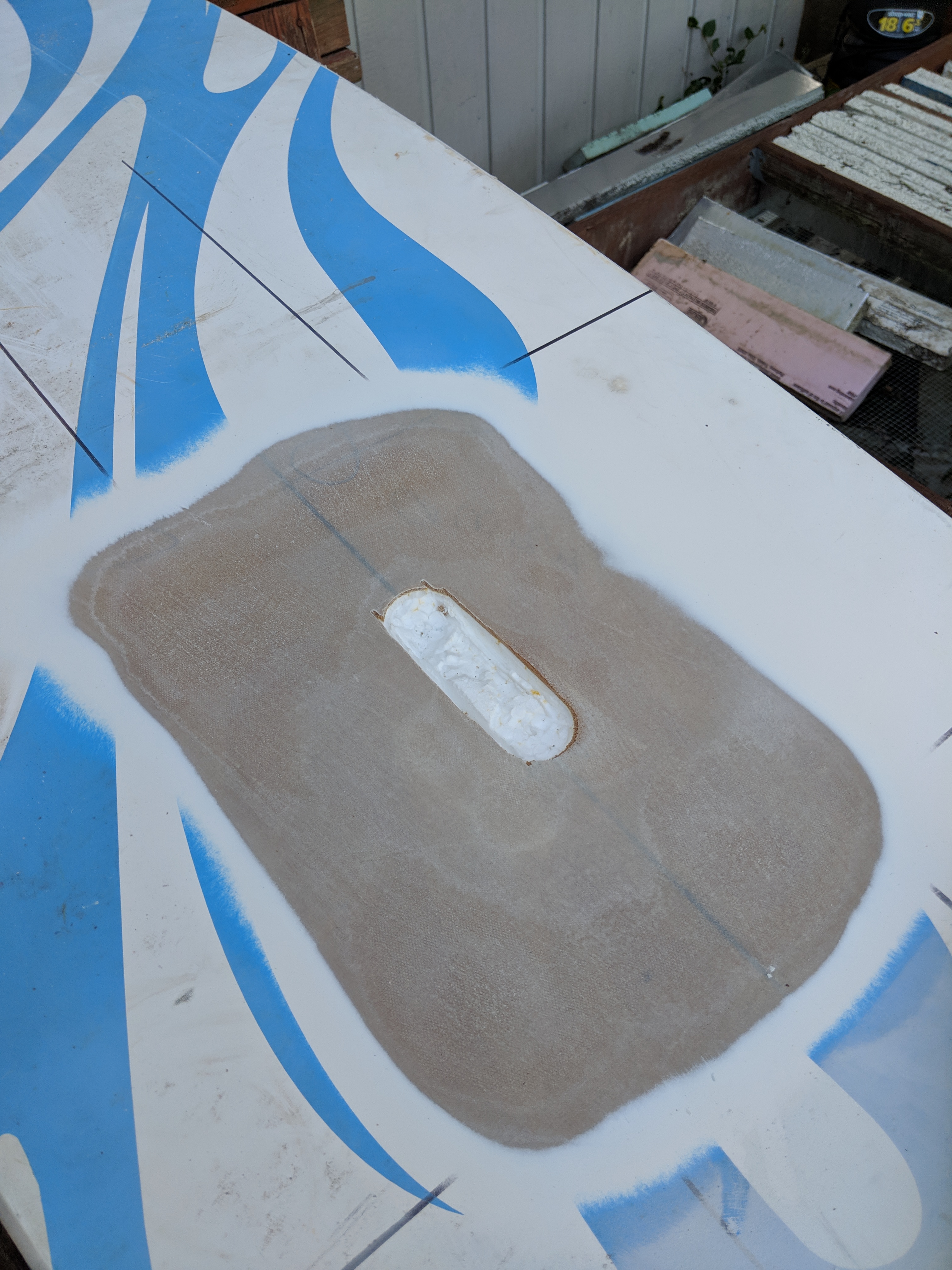
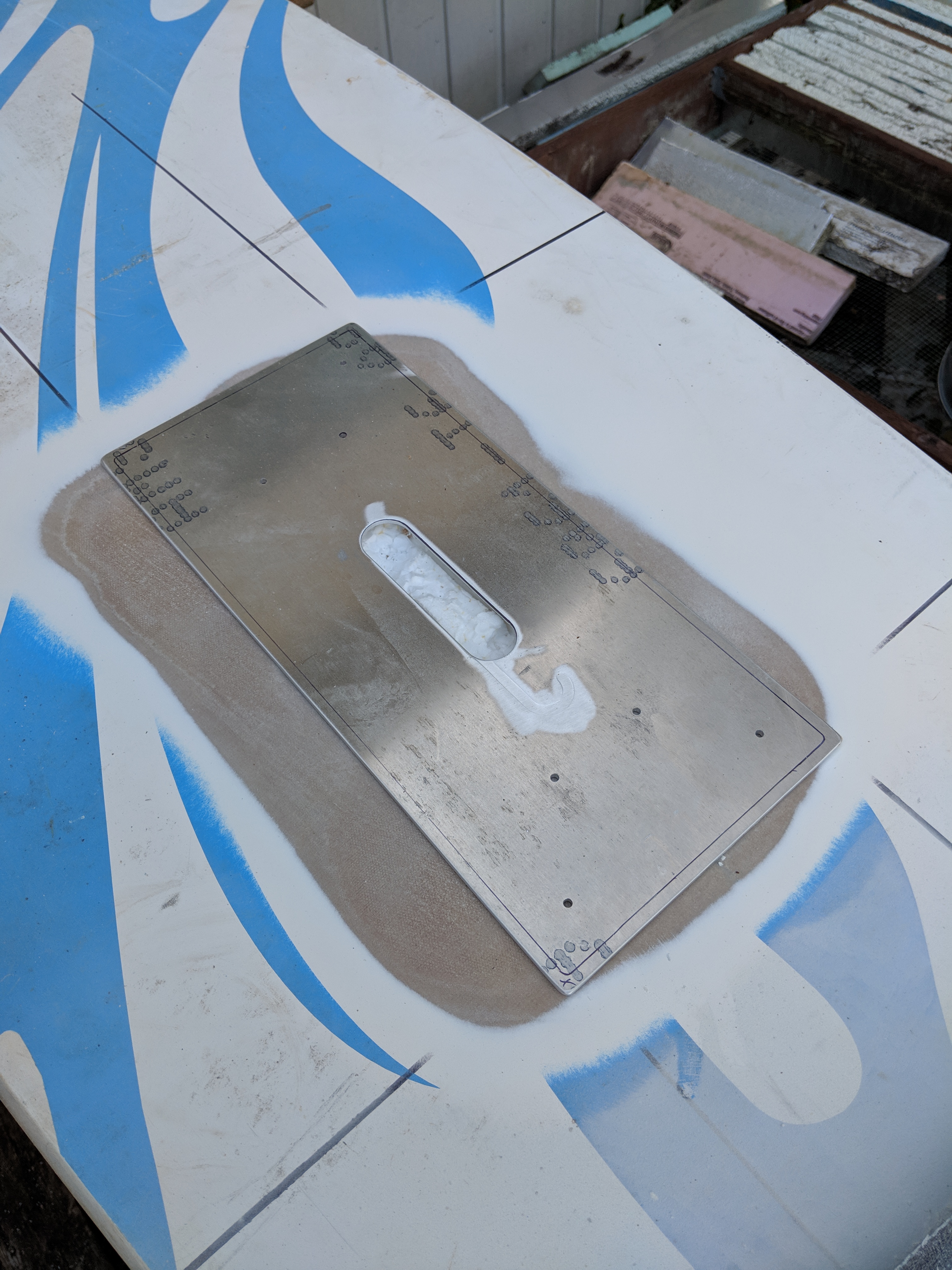
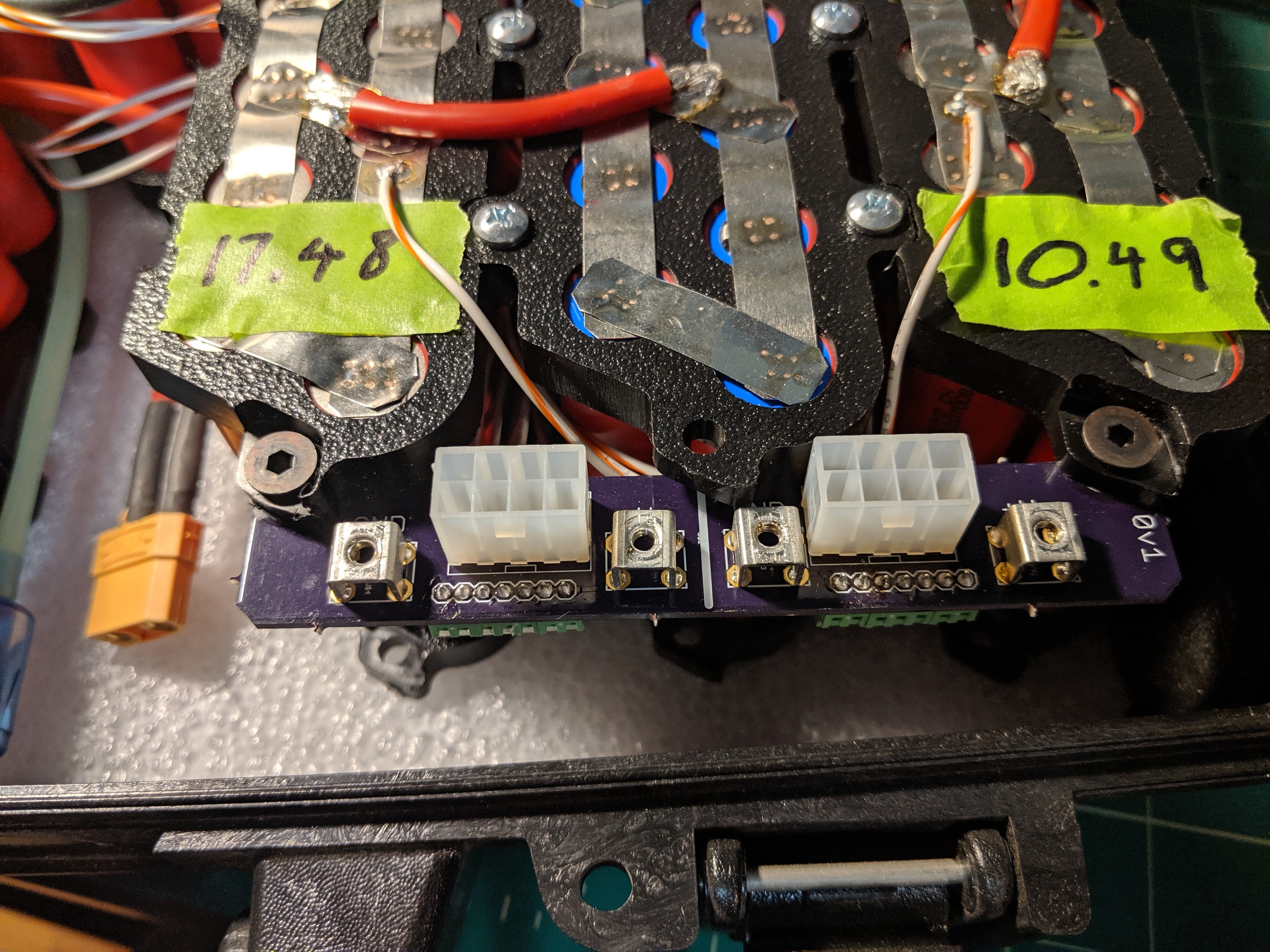
Well, this is a rather large F&%ckup - when I cut the opening in the board for the driver box I left an inch on each edge, which seemed like plenty, but as you can see from this picture when I designed the box I put the connectors on opposite ends.
So with cabling the driver box won’t fit into the opening in the board. I can’t widen the opening in the board because it is in a skinnier part of the board and I’m already really close to the edge.
So probably what I’ll need to do is convert the opening to a hatch and install the electronics directly in the opening.
The good news is I left more space for the battery box, so with connectors it will fit ok (tight, but ok). So the whole board is not a wash. Which would suck because I’ve already installed the mast mount plate.
I’ve been thinking about this some more - and a hatch won’t work because there are tubes that go from the battery box cutout to the drive box cutout and down to the mast mount. These tubes do not expect to be dry, so I can’t use a hatch because I’d have to somehow make those tubes waterproof.
What I think I can do is use my hot wire cutter to scallop styrofoam out of the ends of the cutout and thus get the thing to fit with its complete complement of cables.
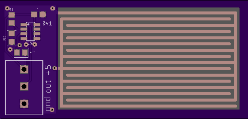
Ok, I did get some useful stuff done. I got my flood sensor PCB’s designed and ordered:
and I’m going to expand the way my error logging happens. The way it works now is there are LEDs for each error:
remote NOT connected
driver temp
driver flood
coolant flow
bat temp
bat flood
pressure
Bat V
but I also want to know more details on both displayed errors and unexpected errors (like for some reason my tilt-pitch-roll sensor isn’t working anymore - it’d be handy to know that)
So I’m building a bridge circuit to go from XBee to Bluetooth so I can run a BT terminal on my phone and get more complete and descriptive error messages. This will be battery operated and sit on the shore logging while I’m out in the water.
In the next rev I’ll put a screen in the display box in addition to the LEDs. Most screens aren’t sunlight readable but for error messages I can stop the board and get close to look at the messages. Assuming the board hasn’t stopped itself
I’m still here! I got surprisingly discouraged while trying to glass the openings in the board, and then when I tried to put it all together I found out that the protrusions for the various tubes wires and hoses made the entire assembly larger than the openings.
And the strategy I had planned on using to strap the battery and driver boxes into the board wasn’t going to work.
This is what’s called the disillusionment phase. All projects have them.
However, now that it’s winter and I’ve got some time to think I came up with some better (but much more time consuming) methods of applying the glass and I’m going to add an OLED screen to the display to give me actual numbers in addition to red error lights.
But I’ve got a lot of other projects on for this winter including a complete esk8 rebuild, so progress will be slow until spring. But I will post as things move.
It’s adam from esk8 news. I messaged you about us both in seattle. I’ve been wanting to make a foil or esurf board. I’m so jealous of your shop.
Sorry about your sandrunner. How far or how much fun did you have before it blew up? Lol
@adman , Just the one day unfortunately. I’ve been looking at the carnage, though and I think I understand enough about what happened that the Sand Runner will live to see another day. Unfortunately not this year - a lot of time and money will have to be poured back into rebuilding and upgrading the battery pack, and I need to seal the battery compartment a lot better than it was. Salt water is really caustic.
I haven’t done a full post-mortem on the blackened packs yet, but at this point I think only 1 cell went off. The others are ok. I won’t use the ones in that bank of course, but the rest I can probably work with. But I need to upgrade the PCB’s to add cel-level fusing and integrated fuses on all the balance leads, etc.
In any event life got in the way and I had to rebuild my deck and paint some of the house. I probably have a couple of weekends left of that work, then I’ll start looking at the eFoil. I might be able to get it ijn the water by early-mid September, but no guarantees.
I’m not as excited about the eFoil as I was when I first started the project, but I’m still interested in seeing if I can get it up and running. All the pieces work, but I haven’t put it together completely yet - I made some minor miscalculations in the insets I cut out of the surfboard, so I need to go back and cut more out.
Then I need to build a curing oven that it will fit in. One of my biggest mistakes was thinking that epoxy cured at room temperature - it really doesn’t. But if I epoxy it and put it in a black box in the back yard for a day or two in the summer it will cure right up.
After that it’s just a bunch of code. the part of the project that is my least favorite.
Keep me apprised on your eFoil project and let me know how I can help - if you start a build thread here send me a pointer.