It’s a nylon printer at work - I think they are 0.1mm layer height. I have a Lulzbot at home but the work printers create such a nice looking part that I try to get away with using them for the final part. Of course I can’t interfere with work job so I can only slip them in occasionally.
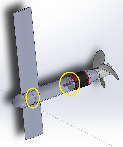
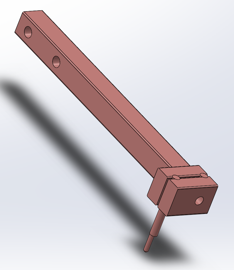
What is the reason of this long tube?
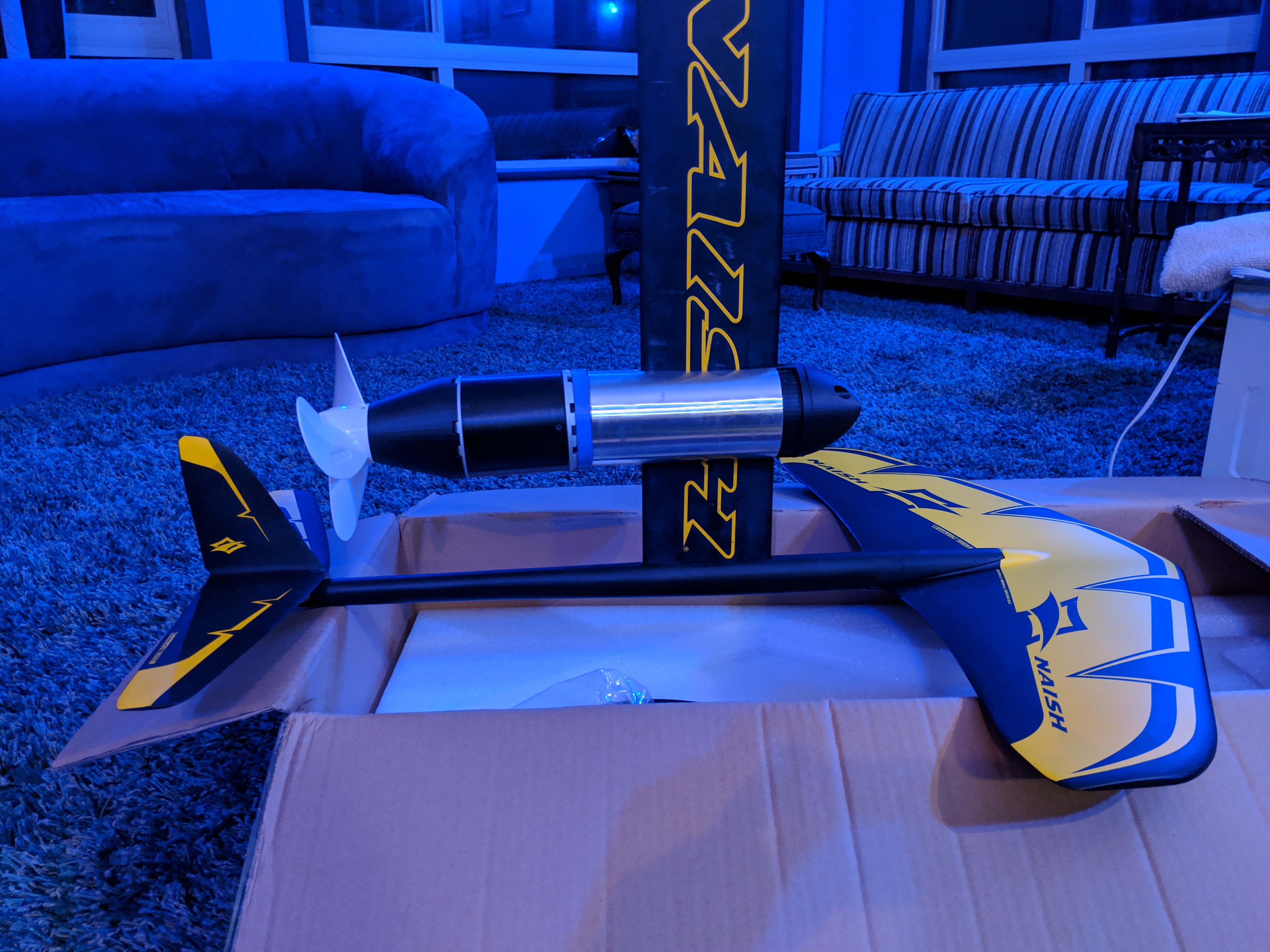
Is it possible that your Prop is mounted reverse?
No reason for the long tube - I happened to have a 12" piece in stock, so I modeled it. Is there an optimal length for these tubes as relates to the position of the wings?
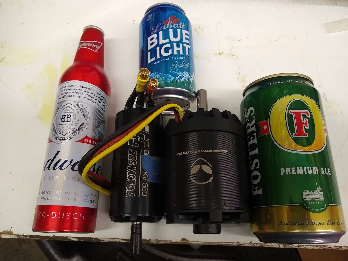
The propeller is just for representation - I grabbed it off GrabCAD. The actual propeller is this one.
First take on the display panel. The LEDs on the right are the battery level and the LEDs on the left are system state conditions.
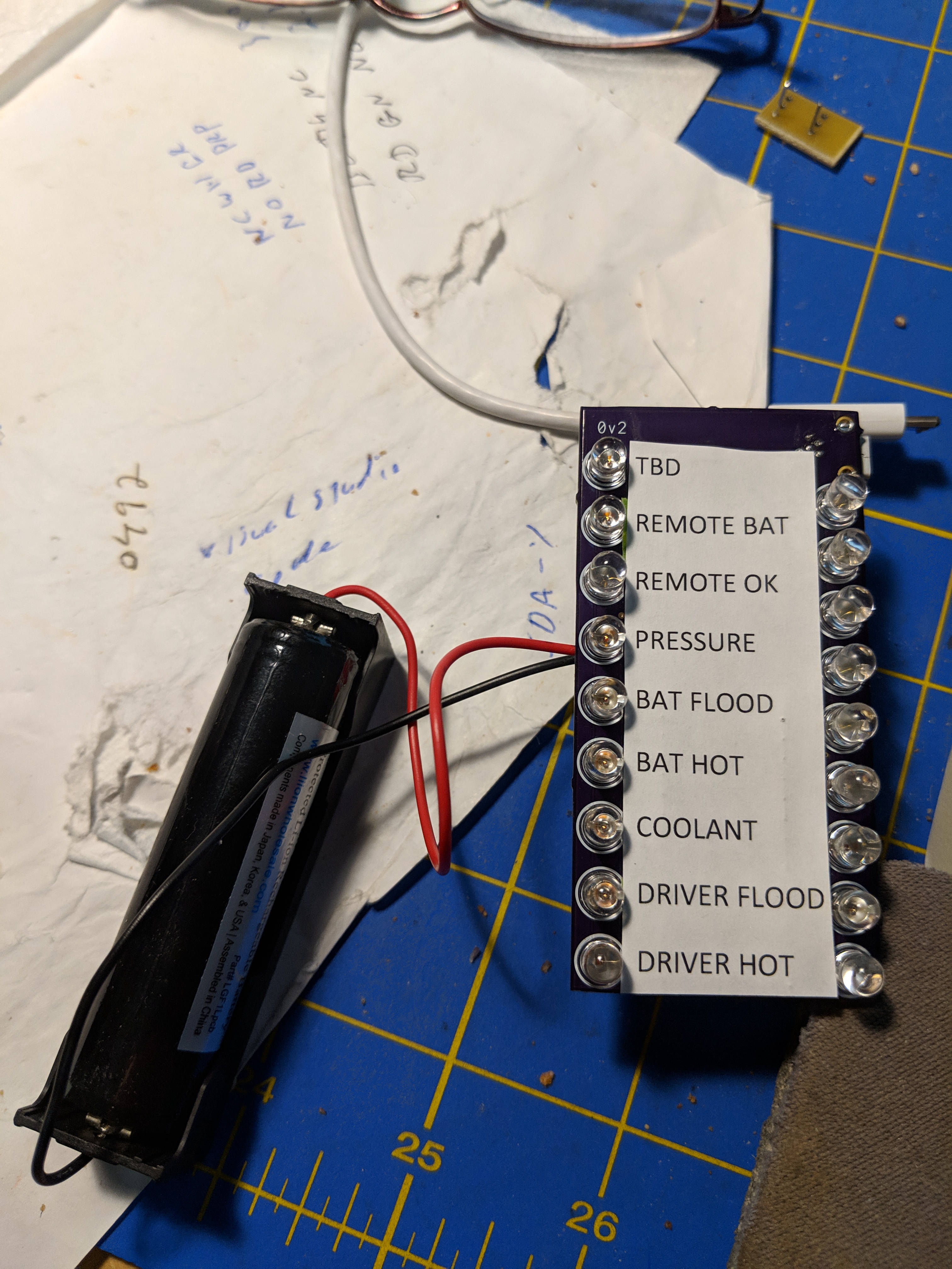
I’ll probably work up more formal (bigger) labels for it since this particular setup isn’t going to be readable while I’m standing on the board. However, it’s coded such that red lights only show up if there’s a problem, so all I really have to do is glance down and if there are no red lights I’m ok.
There is a green light for Remote OK, (which means I have a current radio connection). The top 5 battery LEDs are green, the next 2 are yellow, and the bottom 2 are Red.
The buzzer is in the battery box, so is different code, but it’ll start beeping at the same voltage as the first red LED, 39.2V. It’s a 12S pack, so my usable range is 50.4 to 36.0
This is a standalone unit driven by its own LiIon (3400mAh) cell. It listens on the same radio channel that the remote is transmitting on and the receiver is both transmitting and receiving on.
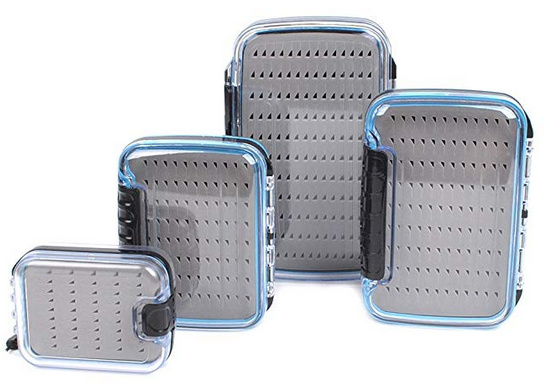
It will be housed in one of those waterproof fly fishing fly boxes, probably this one
and velcro’d to the board. I just need to add a waterproof on-off button and a USB charge port to the box.
For the software nerds in the group, here’s the status string that gets sent across:
// D1e10dBxb0pi0ro0dt0dh0df0bt0bh0bp0bv00.00th0000
The number after each code is binary, so if it’s a 1 I turn the light on and if it’s 0 I turn the light off
// D1 - D1 so we know it’s our message
// e10 - enabled (first digit T/F, second digit disable code)
// dB - Device Battery (source of the message was the battery box)
// xb0 - Xbee connected/not connected
// dt0 - Driver Temperature
// dh0 - Driver Humidity/flood
// df0 - Driver flow
// bt0 - battery temperature
// bh0 - battery humidity
// bp0 - battery pressure
// bv00.00 - battery voltage
// 50.4-36 = 14.4, div 9 = 1.6, so 36, 37.6, 39.2, 40.8, 42.4, 44.0, 45.6, 47.2, 48.8, 50.4
// logging only
// pi00 - Pitch
// ro00 - Roll
// th0000 - throttle position
I’ll also log battery voltage and some sort of time constant. The board as a uSD card on it for logging.
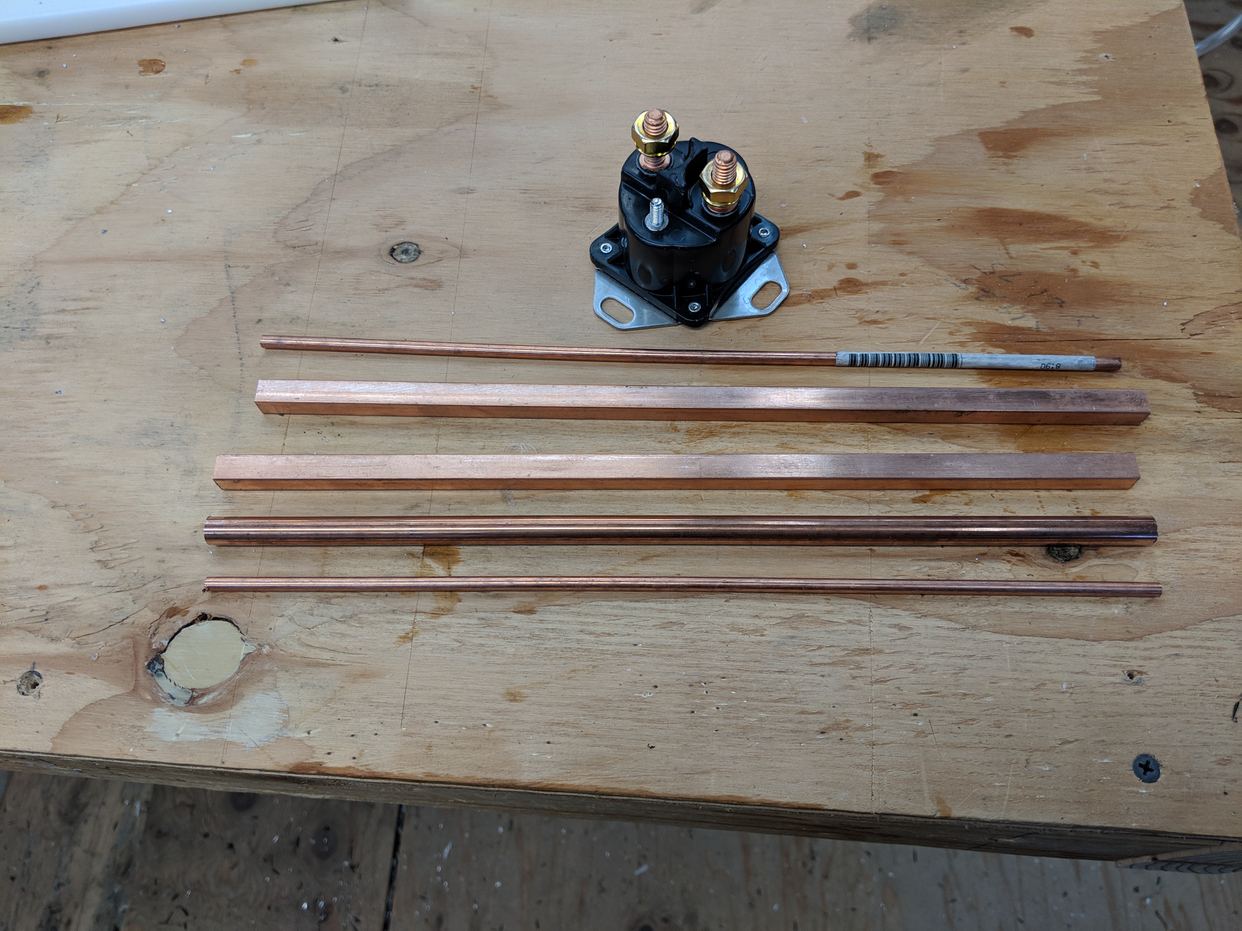
For the machining nerds in the group, here’s the clamps for the motor mount
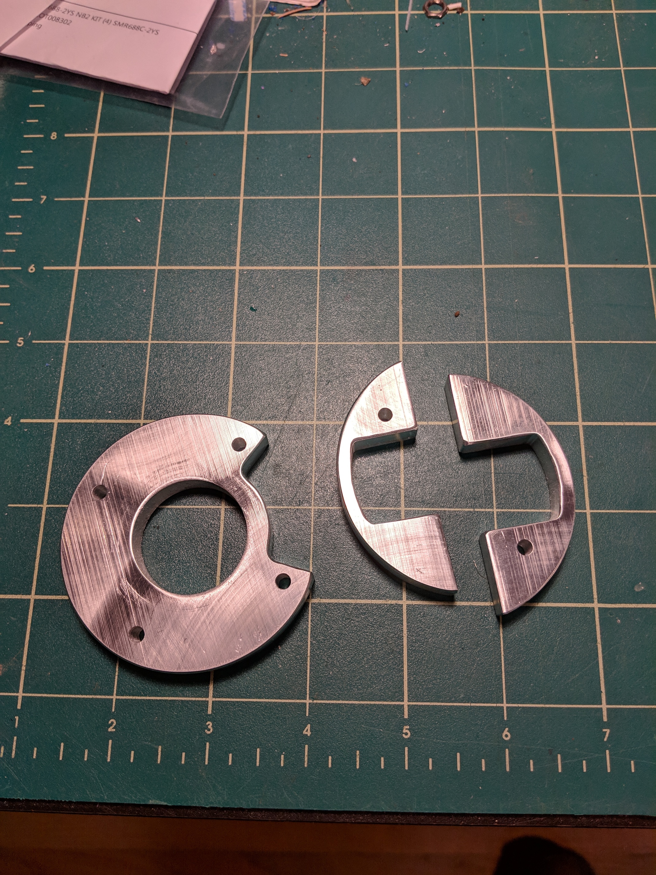
The astute will notice that one of the half-clamps is larger than the other. That was, um, a mistake. But I don’t think operationally it will make a difference since the screws come in from the curved side (to bolt the aluminum tube in place)
2 Likes
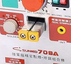
Today I’m going to take a little tangent and work on a battery spot welder. It will be based on what looks to be very mature work from Malectrics (GitHub Here)
I want it to be the same form-factor as the Sunkko welders, basically a box with 2 little arms on the front to make welding tip placement much easier. It’ll be extruded rail open frame, with a motorcycle battery in the back.
I doubt I’ll get much past the enclosure and the welding arms today.
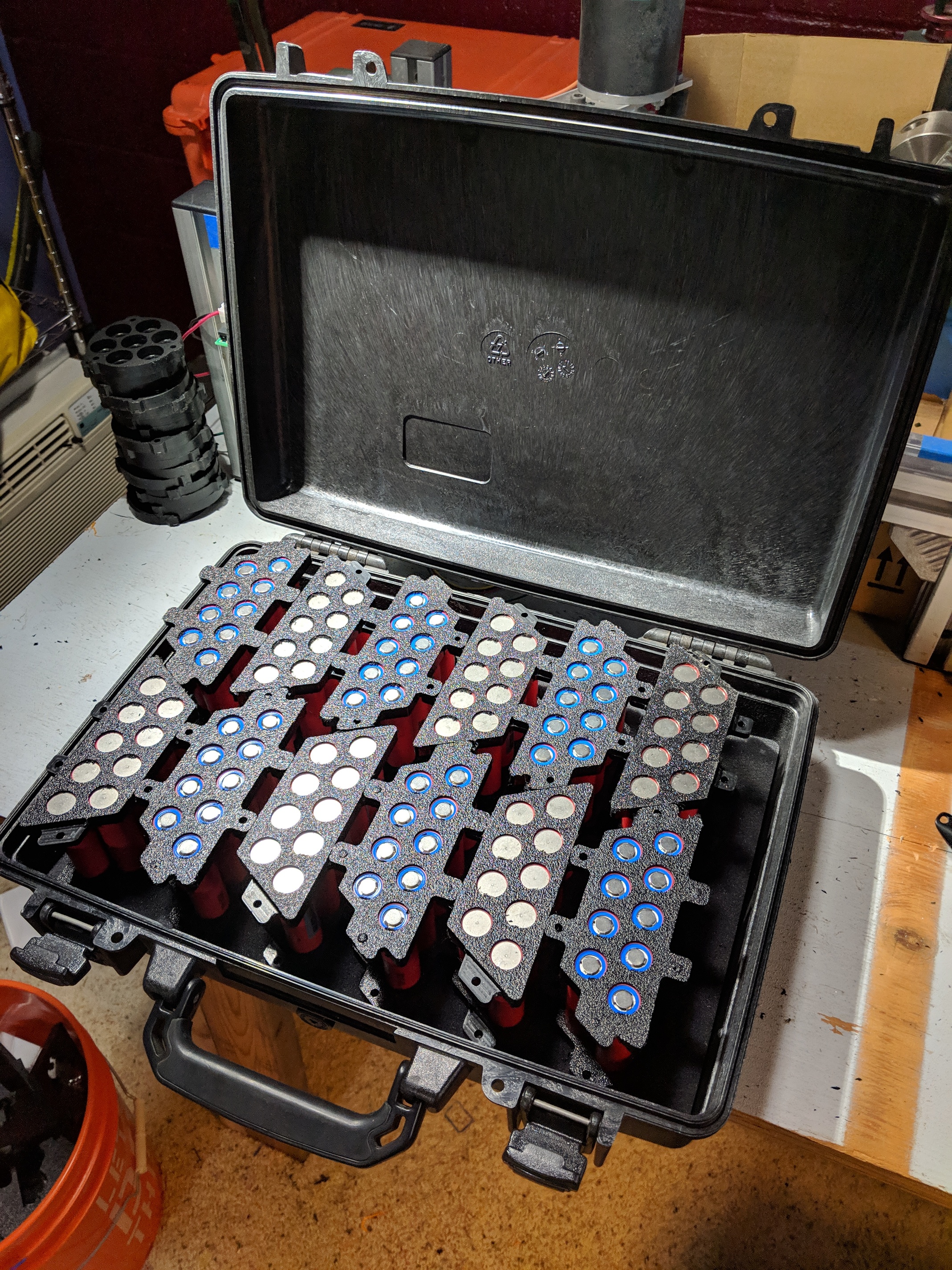
Also on the agenda machining the rest of the battery cages and figuring out why the tilt-pitch-roll sensor isn’t working anymore.
1 Like
I recall you said your box leaked when held under water for a long time. Did you make any improvement to your battery case that helps. I have made some progress with adding O-ring grease to the seal of my leaky box. But I am not satisfied its good enough.
I had an interesting conversation with a friend who has done a lot of work for the navy. He said put about 10 lbs positive pressure in the box and that will keep the water out. I got a small air pump that puts out probably around 8 lbs and am going to pressurize both the battery box and the driver box.
The problem is where to get dry air ![]() I’m still noodling on that, but I think since the pump will be turning on only occasionally (with an anti-backflow valve and assuming no giant leaks) I can just have a small snorkel sticking up and be ok.
I’m still noodling on that, but I think since the pump will be turning on only occasionally (with an anti-backflow valve and assuming no giant leaks) I can just have a small snorkel sticking up and be ok.
Right now this is how I’m hoping to lay out the thing.
It’s much tighter than I had hoped, but I only have 3 components, the air pump, the hard cutoff solenoid and the control board, so I think I can fit them all.
I also found, on closer inspection, that the pressure equalizer valve was very loose in the case. Now I know where the air input line is going to go through.
Ok, well, here is the sum total progress made on the Battery Spot Welder:
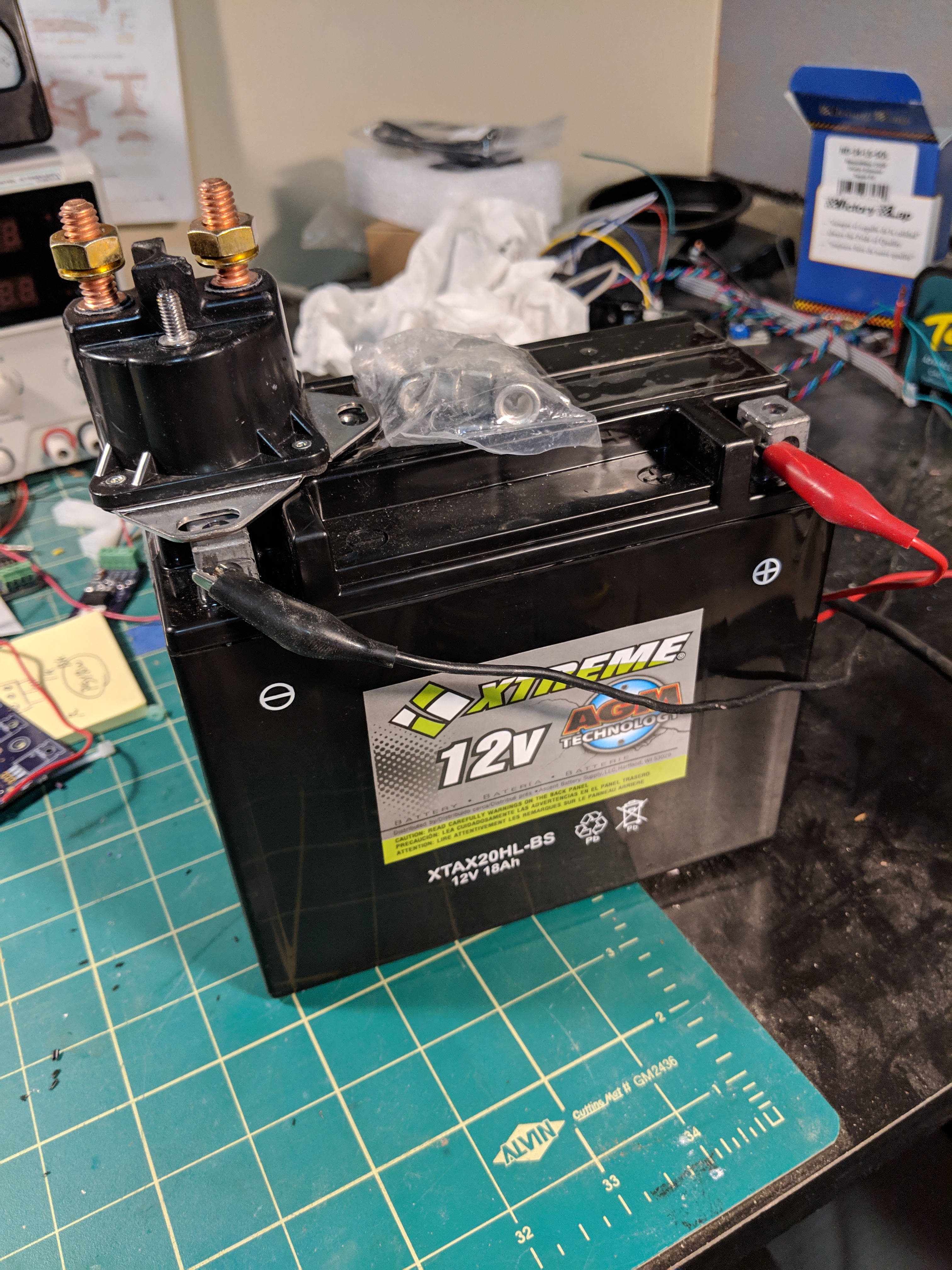
Yes, I got a battery.
It is I think 350CCA and wasn’t that expensive. For now I’m just going to monkey around with using the starter solenoid for proof of concept. Primarily I wanted to settle on a battery right away so I could size the box that the whole contraption is going to live in.
The immediate problem to solve is designing and building the welding arms. I have a couple of ideas that I’m going to model tonight.
The great news is I have a friend flying out to Germany early next week and she has agreed to let me order the Malectrics kit and have it shipped to her house there. Then she’ll bring it back for me. Of course this assumes that it comes back into stock in time.
Just for the record I did get the Tilt-pitch-roll sensor working (it was working, just not reporting correctly), made some updates to the display panel code (bug fixes and all the datapoints for datalogging, but no actual uSD logging code yet) and got all the battery cages machined, so all in all a good day.
1 Like
Related to the positive pressure thing. I have had success doing the following. On my first build I had a small leak, it did not give me a problem until one day I turned the board upside down to clean weeds off the prop while I was in the water. The water that was sitting in the bottom of the battery box found its way into the ESC, and my battery monitors. Things went erratic. Fortunately when it dried out things were all good.
So I added a short length of that blue silicon tubing that passed from the outside to the inside of my enclosure. Just before I was ready to go in the water I would blow into the hose using my mouth. At probably about 2 psi you will hear the air start to leak out. That’s a couple hundred pounds trying to push that door open. Just fold the hose over and clamp it shut. The trapped air will leak out very slowly. It will probably still be leaking out when your done. Everything will stay dry until the air stops leaking out.
1 Like
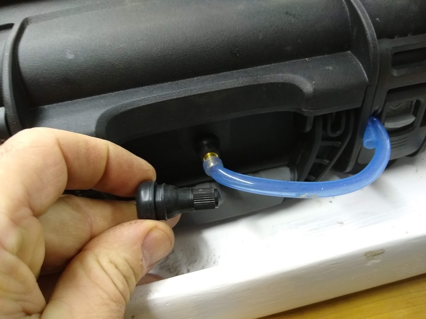
Kill 2 birds with one stone. I used a tire valve stem. I used a step drill to open up the equalizer hole as needed.
1 Like
It’s slowly becoming a thing ![]()
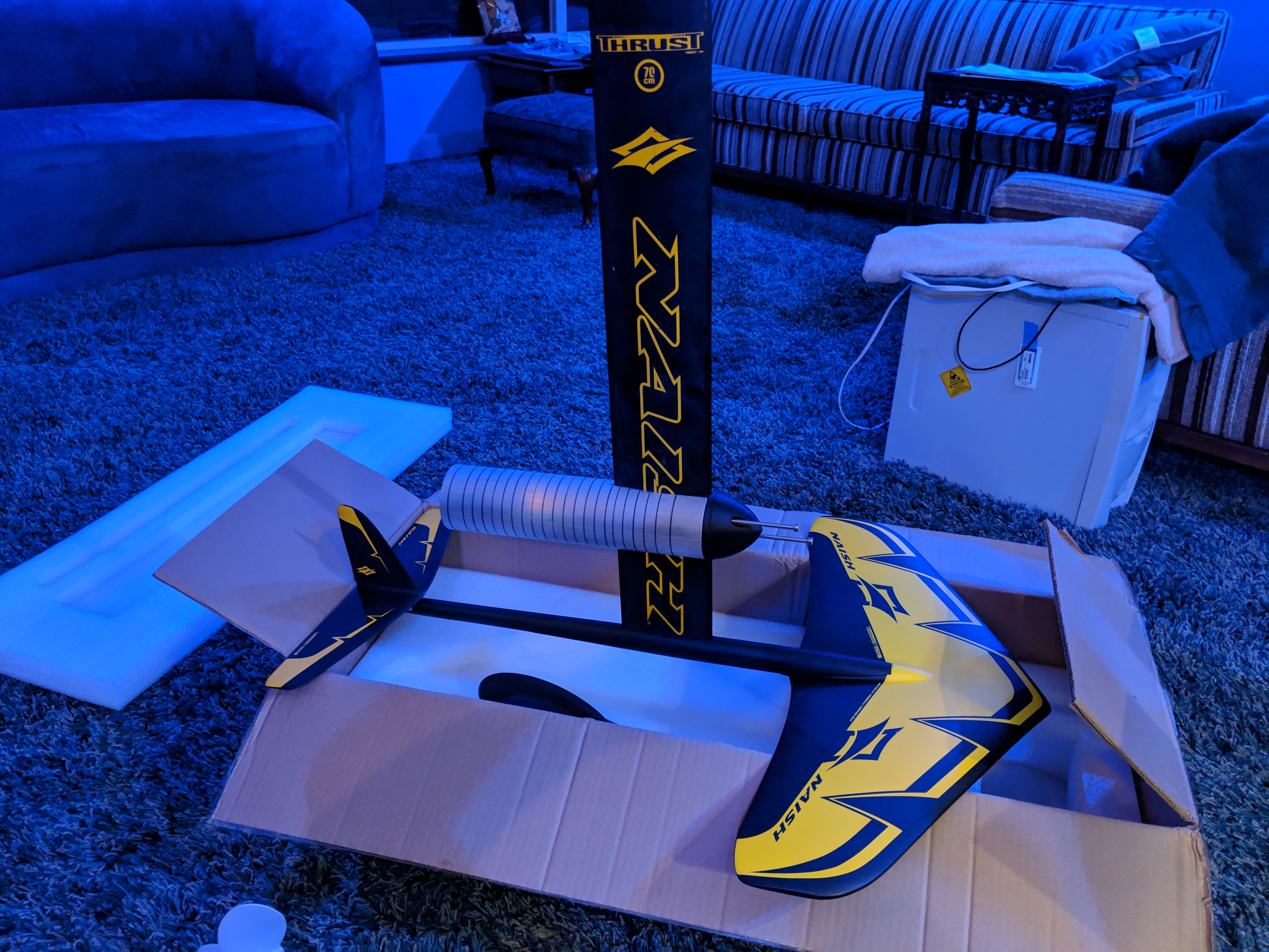
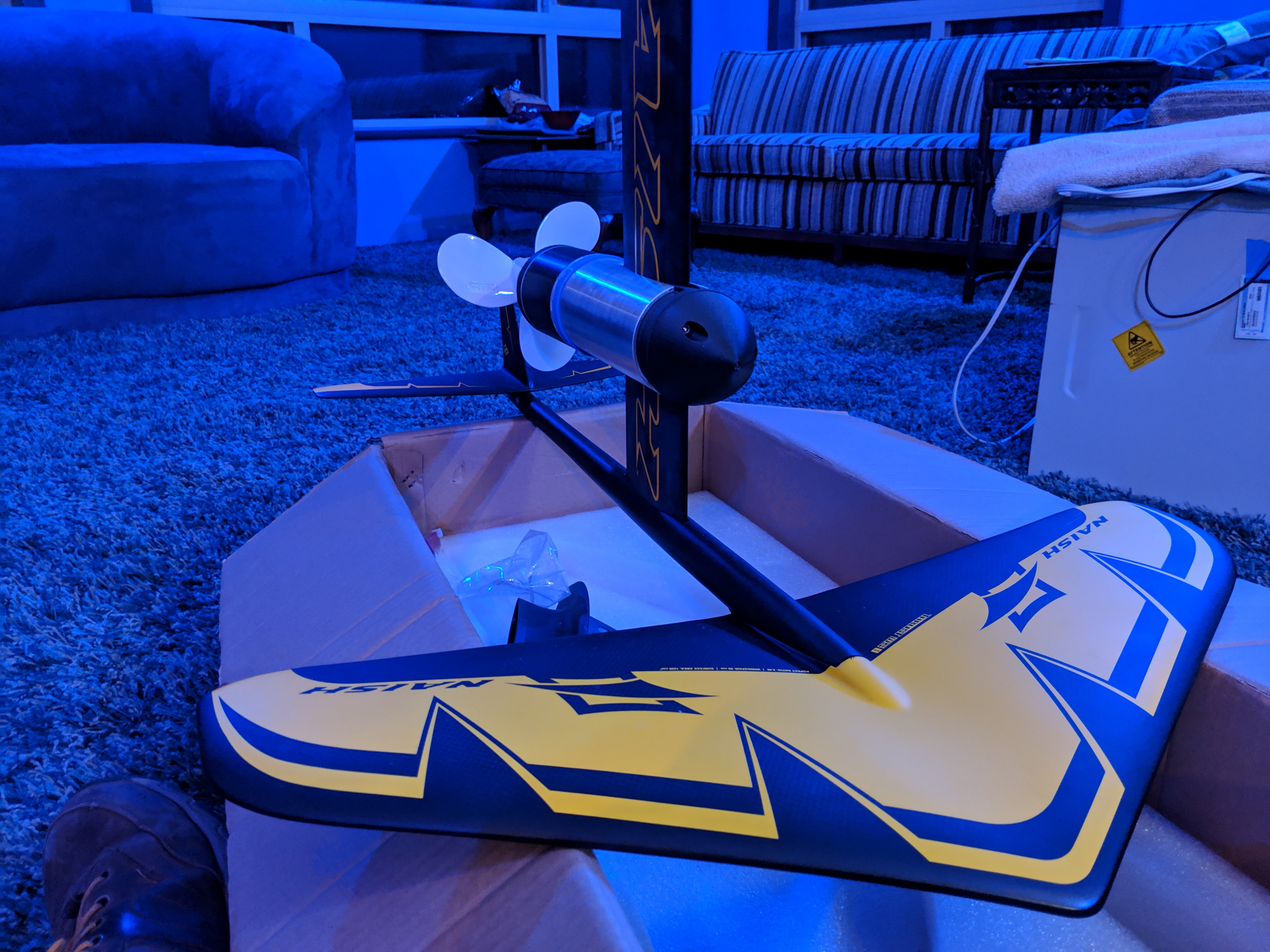
I am going to have to cut the tube considerably shorter, otherwise the prop will run into the vertical stabilizer.
So, instead of doing hard things like epoxying the motor and cutting up the board, I designed my spot welder arm.
Also, after reading through Ben Gold’s build I went and looked at boat hatches - I never realized they were so cheap! This may change my plans. Not sure yet.
speaking of battery spot welders I found out an interesting tidbit. I always thought starter solenoids were just a coil, a ram and some contacts. But apparently there’s more to it than that. I attached the metal plate of the spot welder to negative on the battery, and touched the coil terminal with Positive and it clicked just like it should. But if I’m going to use an N-channel FET to drive the circuit I need to pull low. So I attached the metal plate to positive (thinking it’s just a coil) and touched the coil terminal to negative. and got a really big spark.
Then I switched it back to negative on the plate, tried it again and . . . got a really big spark.
So some sort of protection circuit inside the solenoid is missing its magic smoke and has failed short.
Fortunately the solenoid is riveted shut, so I can drill out the rivets and take it apart.
I have the same foil. I just cut the vertical fin off. You dont need it.
Well, this is basically how it’s going to go together. On final fit I found a couple of things I need to fix, so it won’t be attached until next weekend (this weekend I’m going to try to have a life).
In hindsight I’m kind of glad I broke the nosecone up into 4 pieces, I only have to re-print 3 of them.
1 Like
Maybe there “was” is a diode inside the solenoid to suppress the inductive kick of the coil.
2 Likes
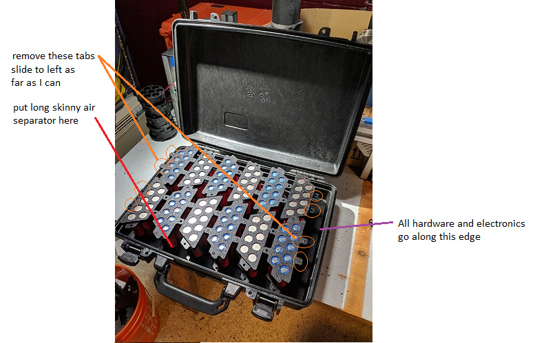
After installing the heat press inserts and trimming the unused tabs I think I’m going to have just enough space to fit all the other bits in.
I also picked up a SUP Leash which should work perfectly for my deadman circuit.
4 Likes
Beautiful 