@Vicdes2 correct. Caveat none of this has actually seen water so I cannot speak to the combination of that motor and that prop personally. However, I think both are in common use here so someone has on-water experience I’m sure.
Just a quick note, Carbon Fiber layup is a lot easier when you have a big vacuum bag and a vacuum pump on a pressure switch. Like night and day. Really.
Also helps a lot if you cut all your pieces to size and have everything ready to go before you start epoxying 
I also found that a 4" angle grinder with a standard diamond tile cutting blade is perfect for cutting the final carbon part.
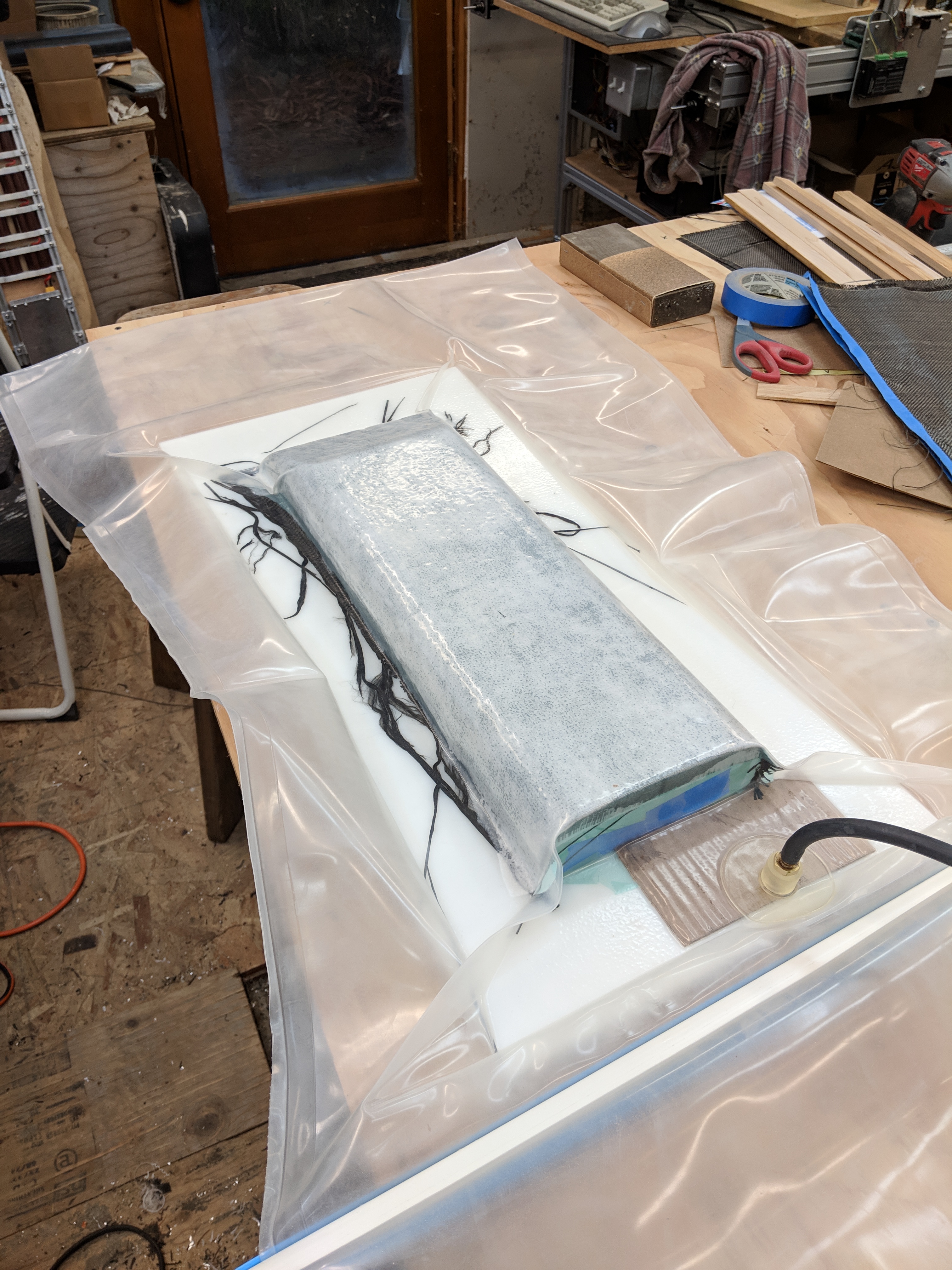
That white piece you see in there is HDPE, the stuff they make cutting boards out of. The epoxy won’t stick to it so it makes removal and cleanup so much easier.
1 Like
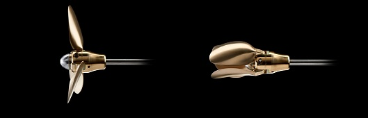
Great to hear that! I used that also for some small parts some years ago. Did not know the material name. That prop motor combo looks great! I need to do such for my next hub cap. As i am mounting the prop directly on the motor to keep it as short as possible, i do not need to transfer any torque through plastic or other parts.
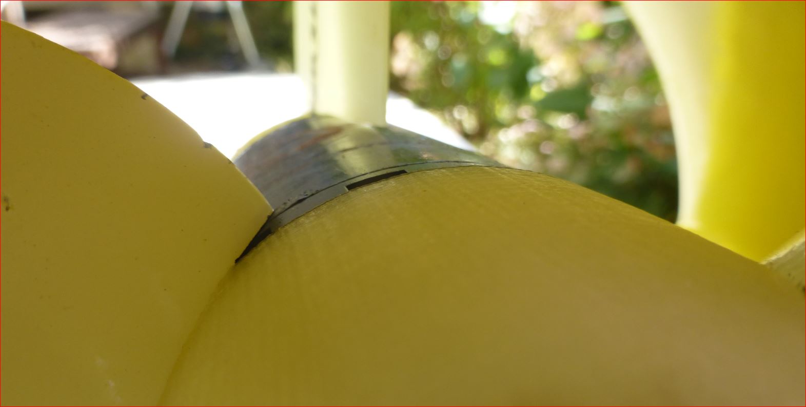
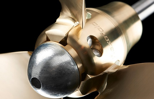
You might not even need a water filter or inlet inside the nose cone, it is coming into the rotating slot between rotor and hub anyhow. Even after hitting a sand bank with stones, the motor was not damaged inside, you can see the scratches and tics on the prop. As it is partly rotating i guess most debris is held off. But you definitely need a defined water outlet, not too much because of friction of the running water inside the motor and not too less to prevent the water from boiling.
I used this prop as well and it is a good choice. If you need more power you can switch to the yamaha 7 1/2 props available with 5,6,7,8,9 inches. Be aware they have a different interface.
I need the 3D data of the hub and prop to be able to print a perfect cap. Anyone knows where i can get it?
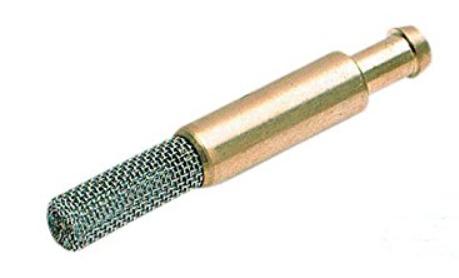
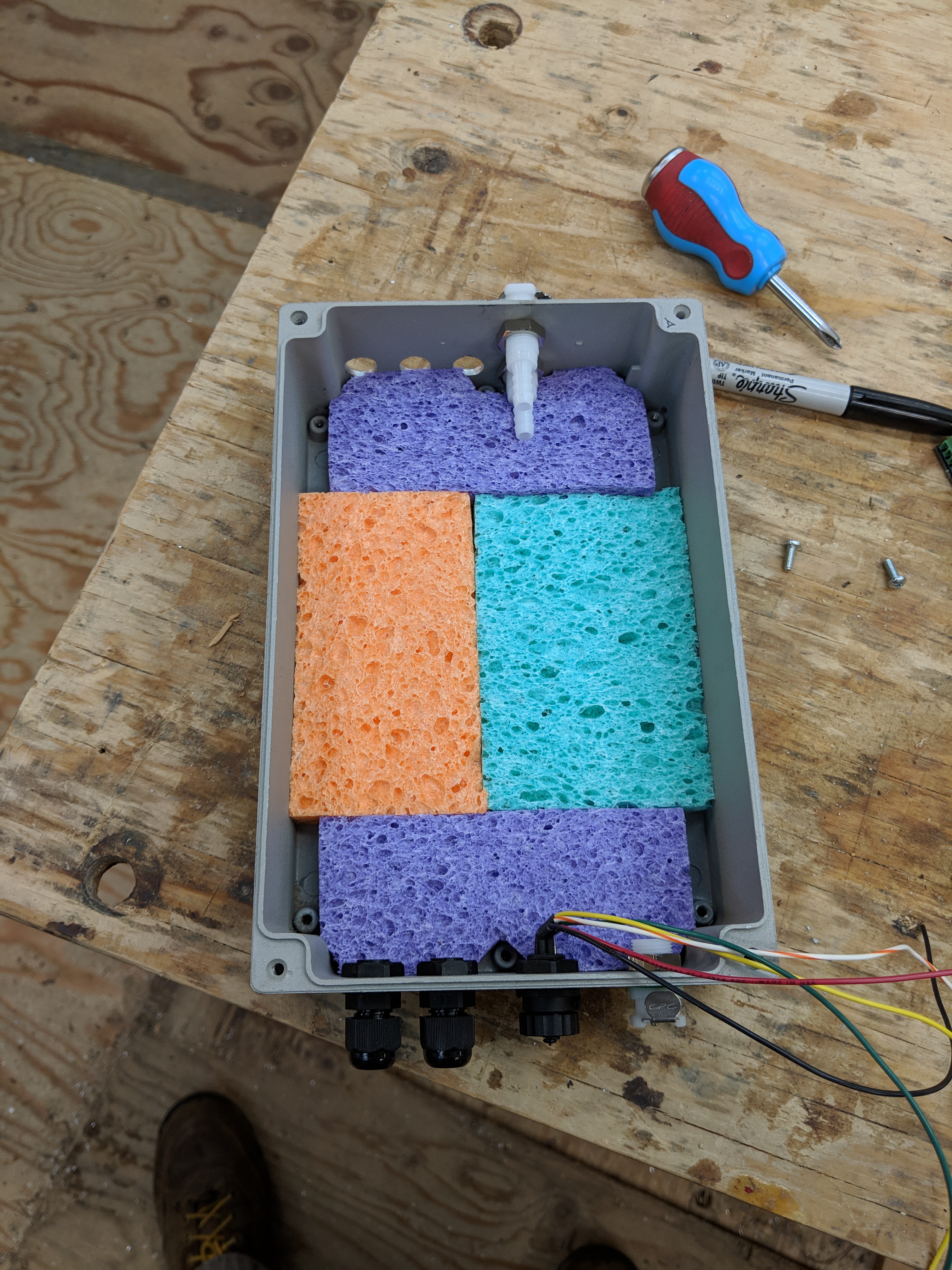
The water filter:
is for the pump that draws water up and through the ESC (Swordfish X). I hadn’t planned on any inlets or outlets for the motor itself - my hope was that having the thing submerged when it’s running, along with what little water will leak in anyway, will keep it cool enough.
I wasn’t able to find a model of that particular prop, but for size and basic modelling purposes I used one by Pascal Lorrain
Here is what it looks like so far
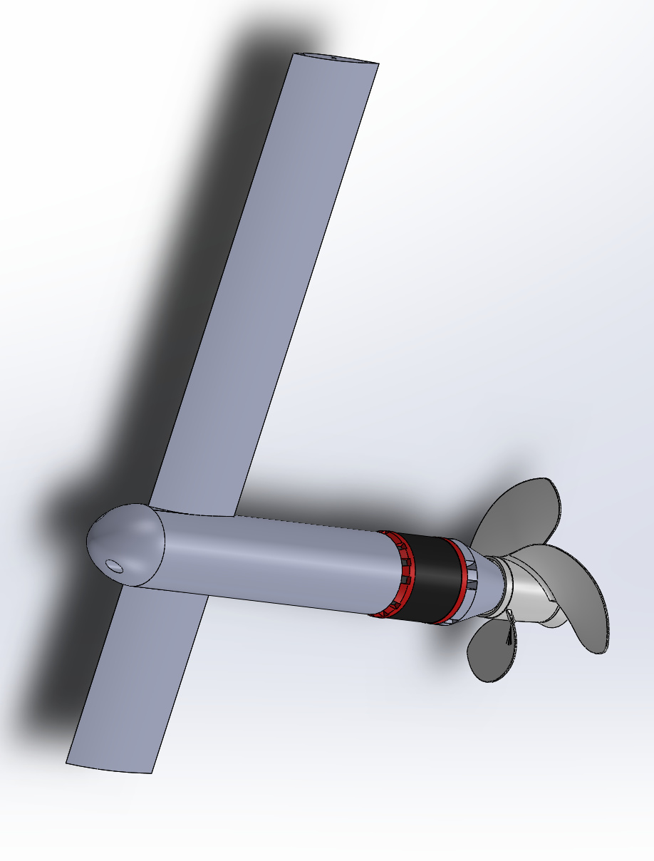
I got the 80100 motor model here. This model doesn’t perfectly match the Alien motor so be aware.
Here is my model for the mast (Naish 70cm, but I’ll be using a 90cm if I can ever get one)
1 Like
I distinctly remember saying that fitting all the components into the driver box was going to be easy. Bwah hah hah hah! I was barely able to fit everything in. I give myself a D- for DFM but an A+ for spatial engineering ![]()
first step was to put the water ingress containment system in
and then, you know, everything else
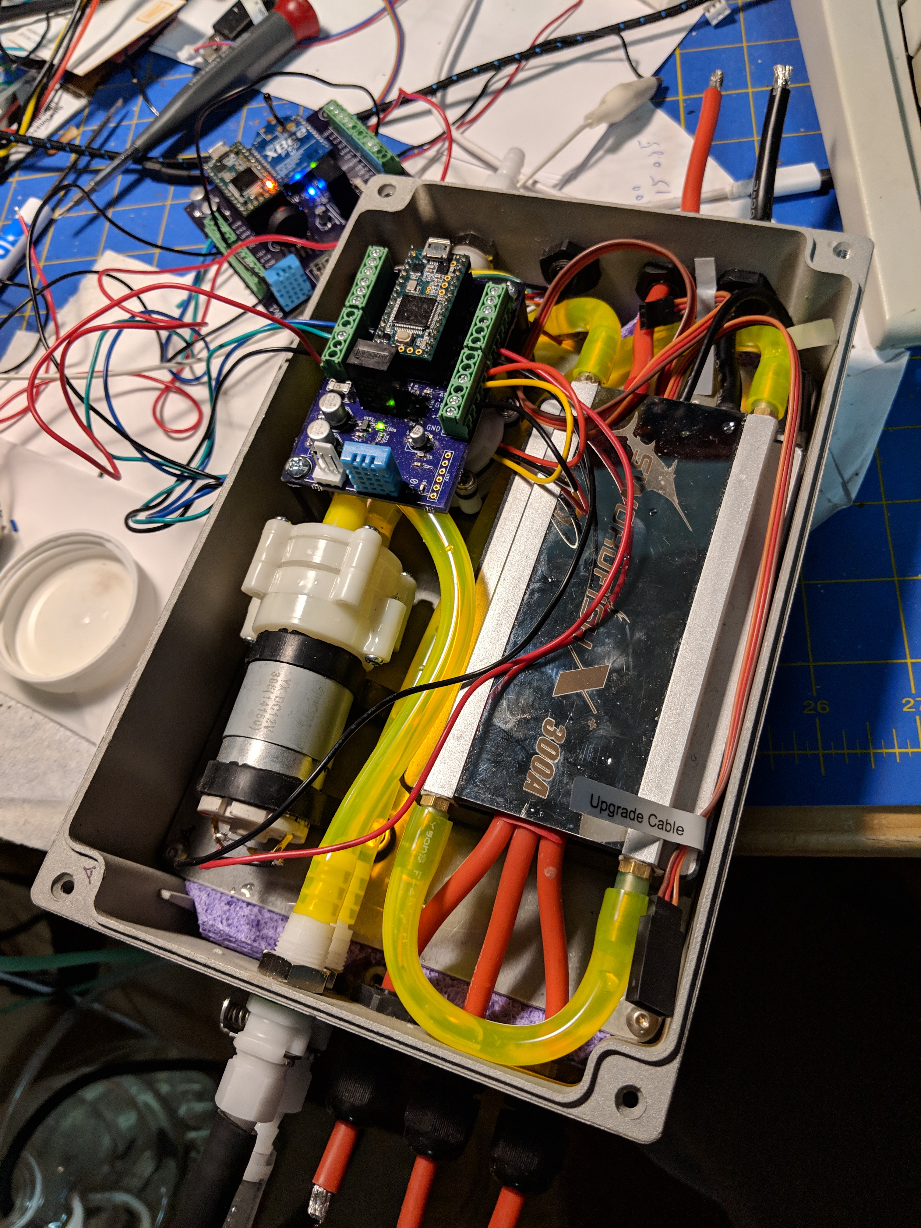
The only thing left to do now is to solder the connectors on the ends of the leads (yes, the power input is going to be a horrible XT90 hack whereby if I ever want to remove the ESC I’ll need to either cut or un-solder the leads). There is, so far as I know, no panel mount waterproof XT90 connector.
I got 2 of these for the inline wiring connectors. I think I’m going to like them.
UPDATE 13/31
No-one has asked, but I spent quite a bit of time looking for appropriate tubing for this project. I looked at everything available at the local hardware store and got some various stuff online. The yellow stuff above is called Tygon fuel line and it’s the Goldilocks of tubing. Not too soft, not too hard, doesn’t kink, doesn’t really require warming up to attach. Sticky where it should be… As you can see I’m kind of enamored of the stuff.
2 Likes
Looks good. What dimensions is the box?
9"x5.9"x3". If I had it to do over again I’d try to keep the same height but go wider.
1 Like
Fresh Water Systems (https://www.freshwatersystems.com)
You can get them on Amazon, but they are 3 times as expensive.
4 Likes
thank you, I can not find in France at a reasonable price, snif …
1 Like
@Manu, they are used on refrigerator water filters - perhaps you could buy a refrigerator water filter system and cannibalize the necessary components?
1 Like
I spent some time yesterday getting code working for the pitch-roll sensor. Amazingly I had one of these BNO055 boards in stock, and this board eliminates the need to do any math on raw outputs - it just gives you the angle without any fuss. So not having ever actually been on a board I arbitrarily chose a pitch limit of 15 degrees and a roll limit of 20 degrees.
Beyond those angles the board assumes you’re falling off and will set the drive signal to neutral before your tether snaps the hard cutoff. My ESC specifically says not to cut power when the motor is spinning, though in this case since there is virtually no inertial load I don’t think it would be a problem, but I’d hate to smoke it.
I’m open to adjusting the angles if any of you with on-water experience cares to weigh in… My guess is the actual numbers are about half of the above.
After that it was all about getting sensor data to the display board and the inevitable problems of servicing multiple serial streams at the same time. But I’ve basically got it worked out. I also had to go back and re-configure all my XBees. I learned recently that the baud rate you set the XBee at externally has nothing to do with the rate at which the XBees actually communicate. So setting it 9600 does not give a higher probability of a clean stream than setting at 115.2k, so I set them all to go as fast as they can. This makes it more likely that there won’t be disturbing interruptions or delays in the throttle position.
Unfortunately I have no pretty pictures since, you know, code.
A rotary switch with a few different modes allowing for different maximum angle tolerances would be interesting, so that anyone could borrow your board ?
You may take advantage of a few ardupilot for APM drawings :
This is a good idea, but probably for the next rev. I’d likely put a BT link in so I can adjust all settings from a phone in realtime. Depending on how the first few test rides go it might jump up in the queue. If I find myself on shore all the time with a laptop re-flashing boards then it’ll bump up fast 
Yes, avoiding to have a computer on the field is exactly the reason why there are RC switches for those settings on Ardupilot.
For one of my esk8’s I just got a FOCBox Unity and I was pleasantly surprised to find out that it had BT built in and came with an app for your phone which did exactly what we are talking about - on the fly change of the settings.
It would be great if some of us could create a group to build the Phone app and interface to Bluetooth. I say this mostly because Android UI is not my strong suit
A couple of shots of the CNC mill cutting the slot for the mast…
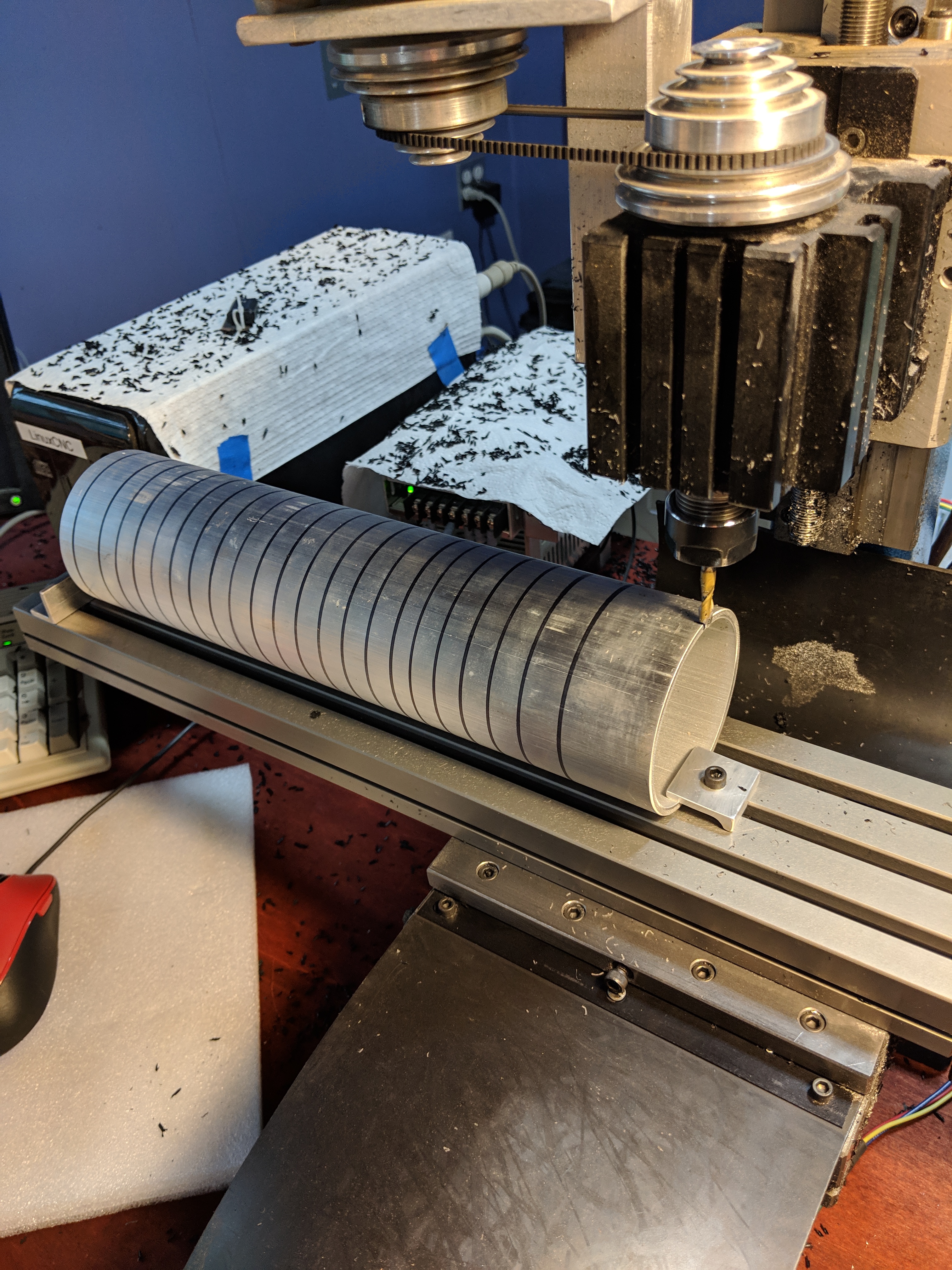
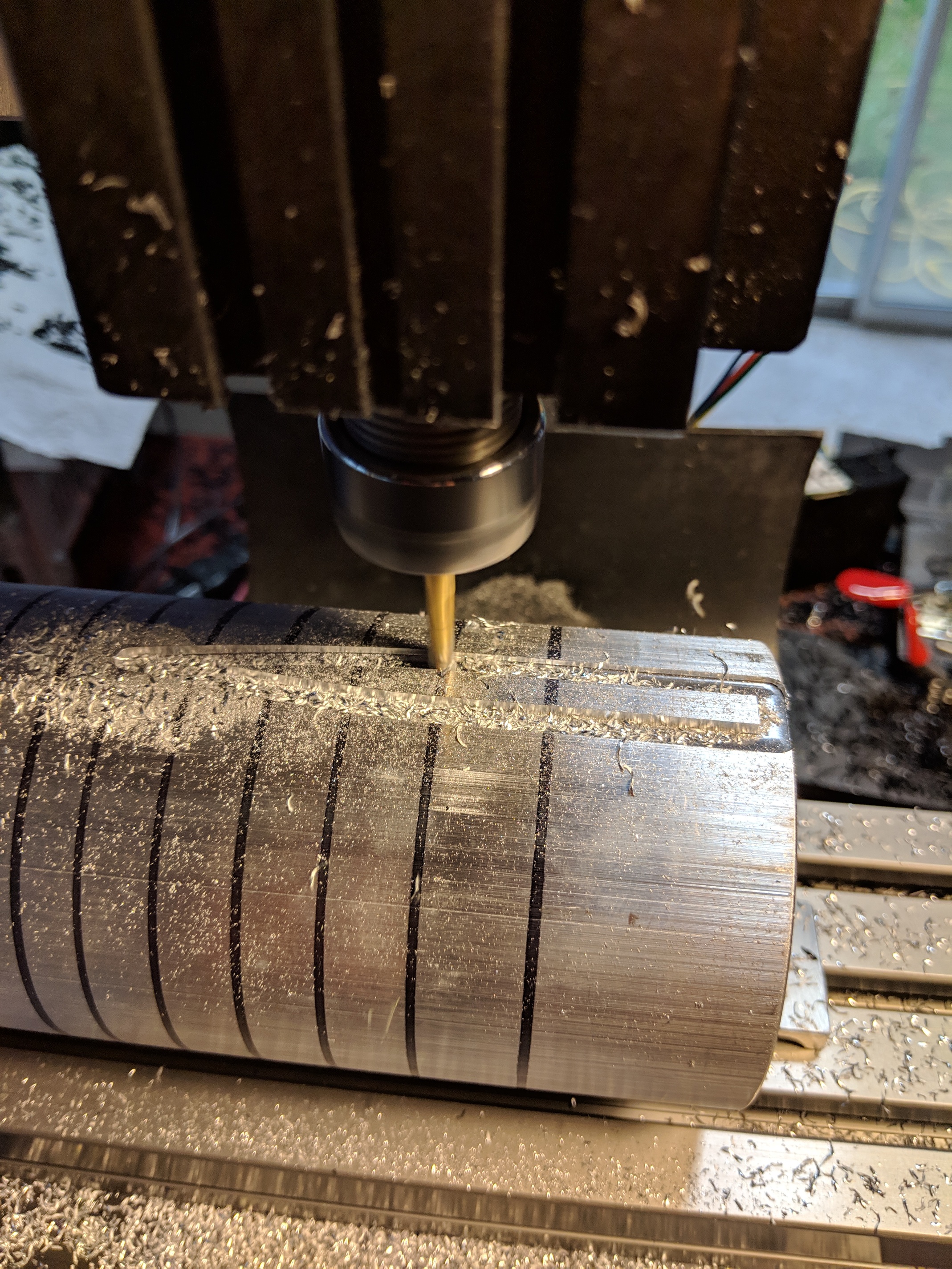
The black sharpie lines have nothing to do with this project - this particular piece of aluminum was once used as a form for making curved diffuser lenses in the toaster oven.
The question is, was I accurate enough in my alignment that the nosecone will fit correctly?
I can’t print the nosecone until the water filter comes in and that’s not until late next week.
So I’m working on the battery. I’m going from 7P to 9P so I need different carriers and to order another $200 worth of cells.
2 Likes
I’m super-intrigued by these folding props mentioned in another thread.
I think Carbon Fiber blades mated to CNC’d brass gears, then encased in a Delrin base might be within my skillset (my skillset does not include casting nor does it include 4 axis milling - yet). But not until rev 2.
2 Likes
Doug,
I would like to know more about your batteries. What are they and where did you get them.? Everyone else is going with 18650 batteries. Those round things you have the batteries mounted in? Did you print those? So why round? Seems like it would waste space?
They are 20700’s. from Lithium Ion Wholesale. Only slightly bigger than the 18650’s but with 25% more capacity. In my case the Pelican case I chose was much bigger than needed to be for the original battery pack, so space efficiency wasn’t really a concern.
The round things are kind of a historical thing - when I made my esk8’s I built the frame out of extruded rail so it made sense to custom design battery carriers that could integrate into the design.
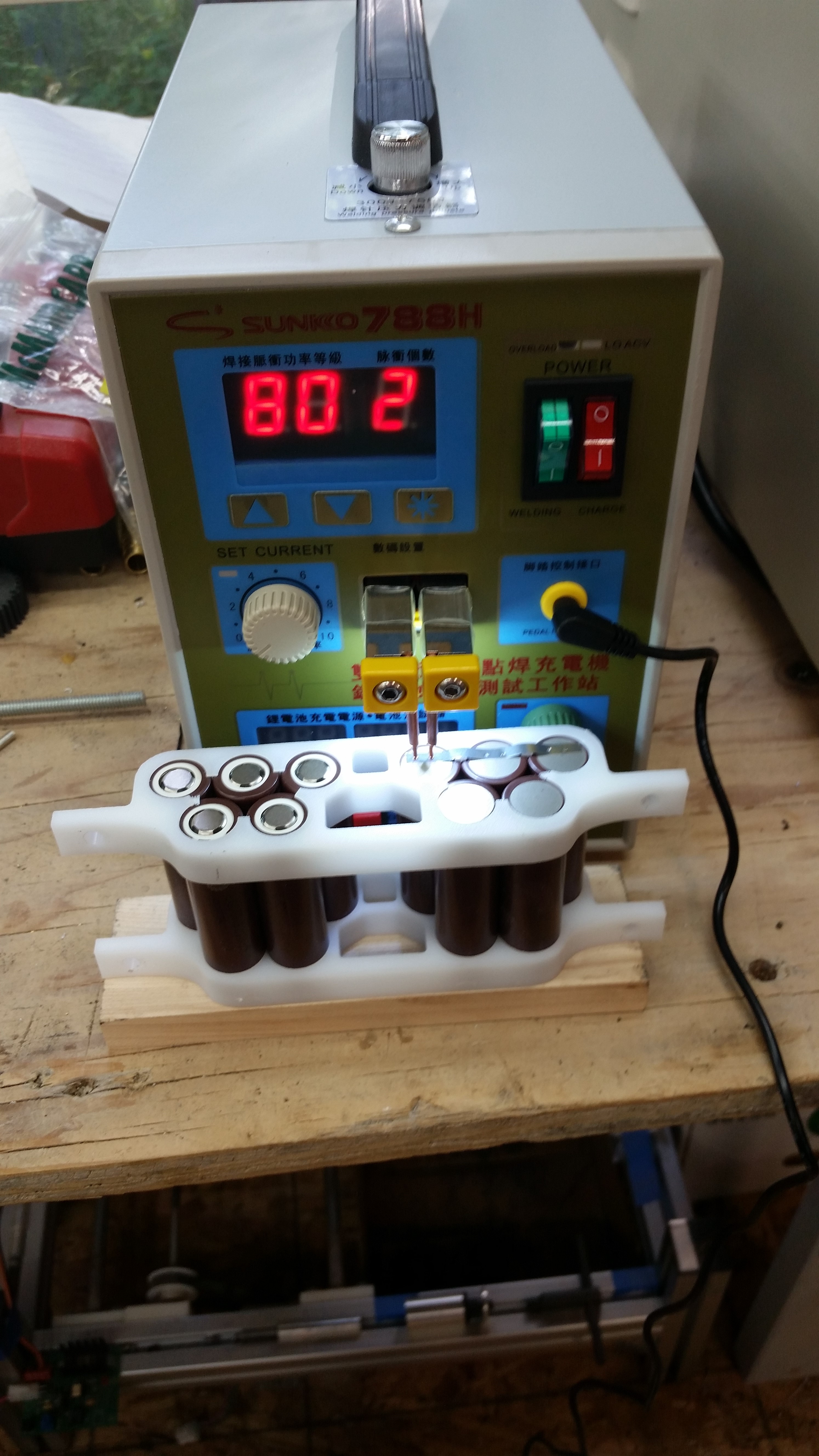
The round ones turned out to be a bad design mostly because connecting them together was going to be more trouble than if I had just built ones with normal tabs on them that I could screw together. As such I’ve abandoned those for a new design:
I like this method because it modularizes the build process and I don’t have to do fish paper or giant heat shrink tube or anything like that, and I can add, subtract or replace Parallel sets any time I need to.
The other, purely theoretical, advantage to these is there’s space between cells and between banks which might aid in cooling and might, if there’s a runaway, limit it to only 1 bank.
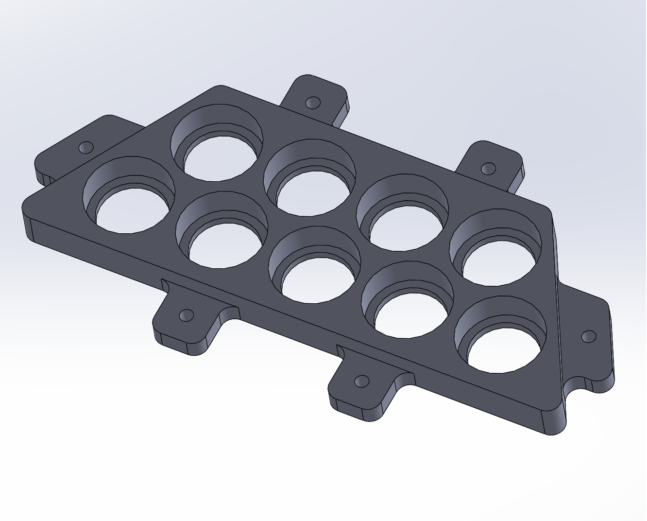
I CNC them out of Starboard (HDPE) from TAP plastic.
The downside to this design is it’s a double-sided cut, and I’m really only a single-sided CNCer. So I’ll have to figure out how to trim the mating tabs from the other side. Probably manually mill them unless I get inspired to actually learn how to register parts for double-sided cutting. Which probably isn’t that hard.
3 Likes