There are always these 8mm bullets which are simple but 8mm bullets will handle huge current vs XT90. Also, these 7mm anti-spark can carry a high current, and if you put anti-spark on both the positive, and negative leads, it is even safer because it does not matter which wire you connect first/last it will never spark and damage your ESC.
Hey guys, I posted a video on the waterproof remote I have been working on for those of you who don’t want to design, solder, code, and piece things together. Just another option that will soon be available for fellow builders and prices between $150-$225 (remote and receiver).
3 Likes
looking great* watched it earlier on youtube, great stuff
1 Like
cool, when will you show us some water tests?
Did find this link about waterproof
1 Like
Happy Easter to all the builders and families! Last step to finalize a semi-decent remote should be an easy task but to me it’s something near impossible: I’d like a sort of feedback from receiver, to know it’s receiving fine, but I’m stuck, @Alexander code doesn’t get me good results (modified with my specs but no transmission)… Or no receiving. Which is the right way to make that Ackpayload stuff work on nrf24? I don’t just need to turn on a LED when TX and RX are linked…I read and studied forums and examples but found nothing easy and effective so far.
Hi and happy Easter. I’ve not used ACKpayload so far, but maybe there are other solutions if ACK is not working. What are the specs, functions or requirements you would like to realize. If you could share the code, it would be easier to help. Do you want to check the received data for plausibility or do you want to send other data back to the sender. If you want to send data like battery status, actual current etc. back to the remote… I thought about a second pipe for this direction (reciver to sender) - I saw this solution in some examples…
.
Tried receiving and sending with two pipes, one for sending and one for receiving, as suggested here:
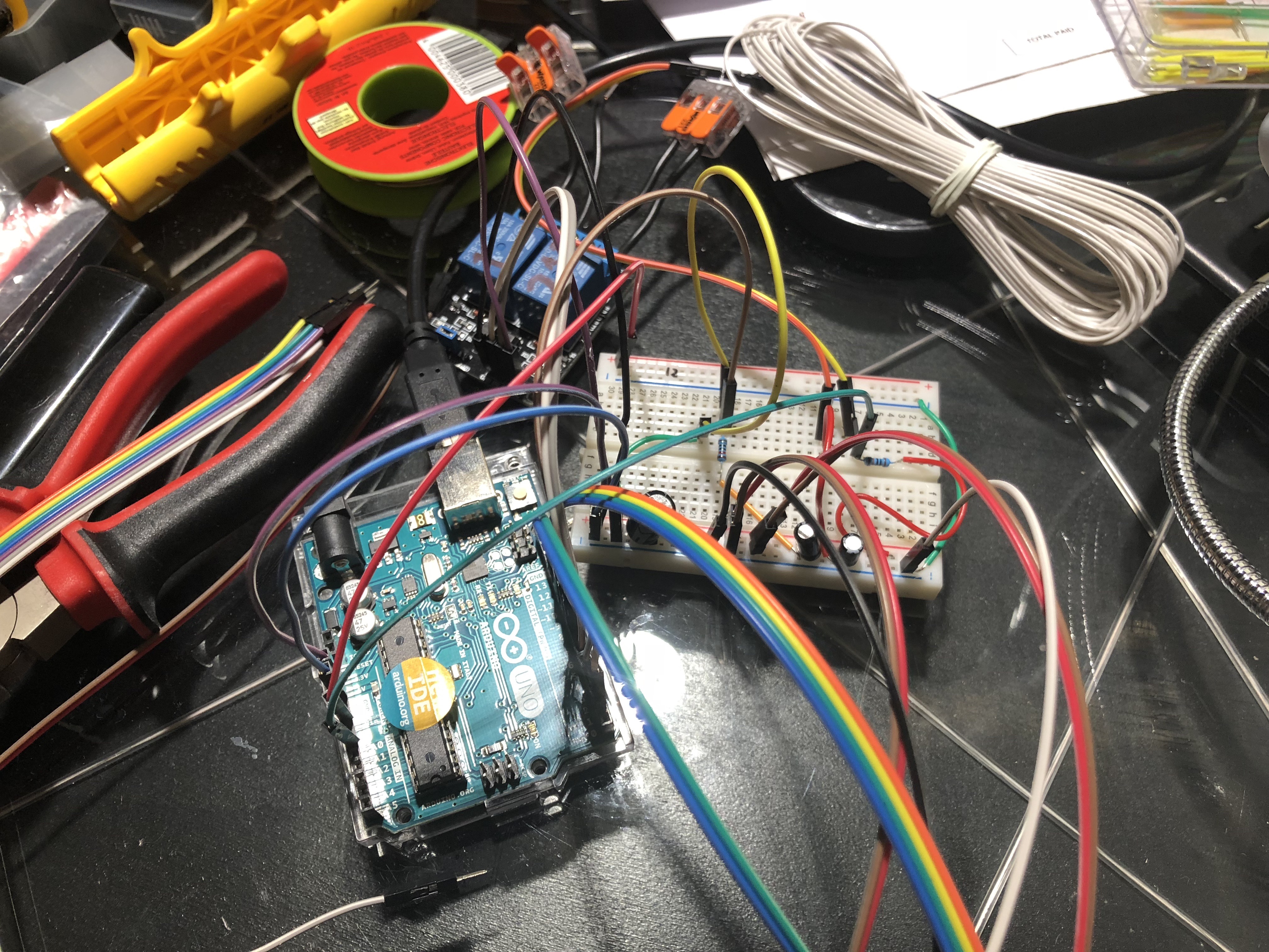
It works but transmission is only half duplex, so you need to switch between transmitting and receiving. I managed to transmit throttle speed from the remote to the board and some simulated values (battery voltage, current, temperature) back from the board side to the handset, the idea is to show these values on an oled display on the hand controller. Changing the power level from low to “RF24_PA_MAX” helped with reliability of the connection. I check if the radio is available on the board side and put the throttle to 0 if there is no signal for 0.7s as a safety measure. The signal is still lost for some fractions of seconds but never for more than 0.7s. My code is still at a very early stage and needs clean up and has no support for the display as I’m still waiting it. Therefore I don’t want to release it at the moment. Setup is on a breadboard, both transmitters are located in a distance of some centimeters. Hall sensor with Hiorts brothers handset works quite well but I also need to implement acceleration and deceleration “ramps” for soft start to protect the planetary gear.
This is a trial for the remote, the basic set up worked fine, ramped throttle, but I think some sort of feedback from the receiver is necessary, at least to know it they’re linked.
I tried to add a remote battery check (Blue LED, Arduino read the battery and turn on if lower than set voltage), a red LED to signal the calibration of the Hall Sensor (5 sec), then (missing in this code!! I don’t know how to make it) there should be 2 LEDs to say “hey, I don’t hear the receiver answering” and “ok, we’re set, let’s fly!”.
On water, for me it should be enought, no more complications. The Transmitter has a REED switch for safety, the receiver will stop the motor after 2 seconds (but that can be adjusted).
Question: How to make the receiver signal the presence and this transmitter read it?
I’ll post the receiver also… after modified this TX, I’ve not touched RX code.
/*
 Ramped Hall sensor Transmitter for EFoil with 4 LEDs, calibration, remote battery low alarm and link status
Library: TMRh20/RF24, https://github.com/tmrh20/RF24/
*/
#include <SPI.h>
#include <nRF24L01.h>
#include <printf.h>
#include <RF24.h>
#include <RF24_config.h>
#include <Servo.h>


RF24 radio(7, 8); // CE, CSN
const uint64_t pipe = 0xE8E8F0F0E1LL;

//Define throttle pin and values

const int hallPin = 0; // Hall sensor pin A0 analog pin
const int batteryPin = A2; //battery voltage
//variables for throttle and hall calibration
int valread = 0;
int valabs = 0;
int valsend = 0;
int val = 0;
Servo esc;

int valMin = 1023;
int valMax = 0;
int numofCalibratinsamples = 600; // number of calibration samples
int calibrationtime = 5000; // Calibrationtime in ms
int batteryval = 0;
float Voltage = 0.00;
//Define the ramp to soften the throttle reaction

#define MIN_PULSE_WIDTH 1500
#define MAX_PULSE_WIDTH 2000
int throttle_current = 0;
int throttle_sp = 0;
int step_size_us = 10;
// Loop update | Step Size | Time to full throttle (1000 - 2000us)
// 20ms | 10 | 2.0s
// 20ms | 15 | 1.3s
// 20ms | 25 | 0.8s

/*Define the 4 LEDs for transmitter visual feedback:
 * BLUE off, on when battery value drops below 3.5V (the reference is the 5.0V step converter which will lower
 * the value when battery is low, so 3.5V should be reasonably 3.3V in reality ...to be tested!)
 *
 * RED = calibration time, when done (5sec) >>
 * >>YELLOW = waiting for a receiver
 * >>GREEN = linked, ready to go!
 */
int B_Pin= 2;  //blue on while battery low
int R_Pin= 3; //Red, on during calibration, swing the throttle!
int Y_Pin= 4; //No link with remote
int G_Pin= 5; //ready to fly!

void setup() {
pinMode (batteryPin, INPUT);

pinMode(2,OUTPUT);
pinMode(3,OUTPUT);
pinMode(4,OUTPUT);
pinMode(5,OUTPUT);

digitalWrite(3,HIGH);
digitalWrite(2,LOW);
digitalWrite(4,LOW);
digitalWrite(5,LOW);

{batteryval = analogRead(batteryPin);
Voltage= map(batteryval, 0, 1023, 0, 5.00);}
while (Voltage > 3.5)
{digitalWrite(2, LOW);}
//now swing pull the trigger few times, min to max, to calibrate the sensor.
  while (millis() <5000){
    valread = analogRead(hallPin);
    //set the Max
    if (valread > valMax){
      valMax = valread;}
    //set the Min
    if (valread < valMin){
      valMin = valread;}
      }
if (millis()<5000) { {
  digitalWrite(3, HIGH);}
if (millis()>=5000)
   {digitalWrite(3, LOW);
  digitalWrite (4, HIGH);}
}

//Open radio pipe, set level, channel etc.

   radio.begin();
   radio.openWritingPipe(pipe);
   radio.setPALevel(RF24_PA_HIGH);
   radio.setDataRate(RF24_250KBPS);
   radio.setChannel(99);


delay(1000);

{batteryval = analogRead(batteryPin);
Voltage= map(batteryval, 0, 1023, 0, 5.00);
 }
Serial.begin(9600);
}

void loop() {
  if (Voltage > 3.5)
{digitalWrite(2, LOW);}
else
{digitalWrite (2, HIGH);}

    valread = analogRead(hallPin); //Read input from analog hallPin and store in val
     Serial.print("valread: ");
     Serial.print(valread);

    // Scale throttle analog value to ESC PWM min and max values (1000us to 2000us)
    throttle_sp = map(valread, valMin, valMax, MIN_PULSE_WIDTH, MAX_PULSE_WIDTH); //mapping val to minimum and maximum(Change if needed)

    //esc.write(val); //using val as the signal to esc

{   throttle_current = (throttle_sp);  //era disattivato
if ( throttle_current > throttle_sp ) {
// Decreasing throttle faster due to slow response of ESC on decel
throttle_current -= (step_size_us * 2) ;
throttle_current = max(throttle_current, throttle_sp); }
else if ( throttle_current < throttle_sp ) {
// Increasing throttle slowly
throttle_current += (step_size_us /2);
throttle_current = min(throttle_current, throttle_sp);}
}

// Final min checks
{throttle_current = max(throttle_current, MIN_PULSE_WIDTH);
// Final max checks
throttle_current = min(throttle_current, MAX_PULSE_WIDTH); }

Serial.print(" throttle SP:" );
Serial.println(throttle_current);

// Ramp throttle to desired target
{esc.write(throttle_current);
}
// Send ramped throttle value to receiver
radio.stopListening();
radio.write(&throttle_current, sizeof(throttle_current));

}This is the receiver:
/*
 * RECEIVER
 * Library: TMRh20/RF24, https://github.com/tmrh20/RF24/
*/

#include <Servo.h> //Using servo library to control ESC
#include <SPI.h>
#include <nRF24L01.h>
#include <RF24.h>
RF24 radio(7, 8); // CE, CSN

const uint64_t pipe = 0xE8E8F0F0E1LL;
Servo esc; //Creating a servo class with name as esc

int escpin = 9; // esc pwm pin
int timer = 0; // esc shutoff
int val = 0;

//Min and max pulse
int minPulseRate = 1000;
int maxPulseRate = 2000;

void setup() {
Serial.begin(9600);
// Serial.setTimeout(500);

esc.attach(escpin, minPulseRate, maxPulseRate);

esc.write(0); // init esc with 0 value

radio.begin();

radio.openReadingPipe(0, pipe);
radio.setPALevel(RF24_PA_HIGH);
radio.setChannel(99);
radio.startListening();
}

void loop() {
if (radio.available()) {

int text;

radio.read(&text, sizeof(text)); //orignal

Serial.print("Trottle: ");
Serial.println(text); //original


esc.write(int(text)); //original
timer = 0; // reset shutoff timer
}
else {
timer += 1;
}
if (timer > 2000) {
esc.write(0); // safety, motor stops if connection lost for 2s
timer = 0; //stop and reset the counter
}

}
Any thought, tip and help will be very welcomed!
Why not use the AutoACK Payload? Seems to be much faster: Time comparison between normal TX-RX mode and Auto Ack payloads – Just Electronics
and is made for exact that purpose:
")
1 Like
…I’m on it… almost! Today I modified the sketch adding all the 4LEDs functions and made 3 working, still I can transmit on (pipe) the only and there’s no acknowledge back but I know that I’m close… I should be (after all this trying!) ramp, cal and battery are there, but yellow LED never go out even if the throttle transmit to receiver and esc properly… ack back is missing.
Like I said… I was there! This now works
TRANSMITTER;
/*
  Ramped Hall sensor Transmitter for EFoil with 4 LEDs, calibration, remote battery low alarm and link status
  Library: TMRh20/RF24, https://github.com/tmrh20/RF24/
*/
#include <SPI.h>
#include <nRF24L01.h>
#include <printf.h>
#include <RF24.h>
#include <RF24_config.h>
#include <Servo.h>


RF24 radio(7, 8); // CE, CSN

bool connected = false;
short failCount;
const uint64_t pipe = 0xE8E8F0F0E1LL; // If you change the pipe, you will need to update it on the receiver to.
unsigned long lastTransmission;
//Define throttle pin and values

const int hallPin = 0; // Hall sensor pin A0 analog pin
const int batteryPin = A2; //battery voltage
//variables for throttle and hall calibration
int valread = 0;
int valabs = 0;
int valsend = 0;
int val = 0;
Servo esc;
int text;
int valMin = 1023;
int valMax = 0;
int numofCalibratinsamples = 600; // number of calibration samples
int calibrationtime = 5000; // Calibrationtime in ms
int batteryval = 0;
float Voltage = 0.00;
//Define the ramp to soften the throttle reaction

#define MIN_PULSE_WIDTH 1500
#define MAX_PULSE_WIDTH 2000
int throttle_current = 0;
int throttle_sp = 0;
int step_size_us = 16;
// Loop update | Step Size | Time to full throttle (1000 - 2000us)
// 20ms | 10 | 2.0s
// 20ms | 15 | 1.3s
// 20ms | 25 | 0.8s

/*Define the 4 LEDs for transmitter visual feedback:
   BLUE off, on when battery value drops below 3.5V (the reference is the 5.0V step converter which will lower
   the value when battery is low, so 3.5V should be reasonably 3.3V in reality ...to be tested!)

   RED = calibration time, when done (5sec) >>
   >>YELLOW = waiting for a receiver
   >>GREEN = linked, ready to go!
*/
int B_Pin = 2; //blue on while battery low
int R_Pin = 3; //Red, on during calibration, swing the throttle!
int Y_Pin = 4; //No link with remote
int G_Pin = 5; //ready to fly!

void setup() {
  pinMode (batteryPin, INPUT);

  pinMode(2, OUTPUT);
  pinMode(3, OUTPUT);
  pinMode(4, OUTPUT);
  pinMode(5, OUTPUT);

  digitalWrite(3, LOW);
  digitalWrite(2, LOW);
  digitalWrite(4, LOW);
  digitalWrite(5, LOW);


  //now swing pull the trigger few times, min to max, to calibrate the sensor.
  while (millis() < 5000) {
    digitalWrite(3, HIGH);
    valread = analogRead(hallPin);
    //set the Max
    if (valread > valMax) {
      valMax = valread;
    }
    //set the Min
    if (valread < valMin) {
      valMin = valread;
    }
  }
  //if (millis()<5000)
  {
    //digitalWrite(3, HIGH);}
    if (millis() >= 5000)
    { digitalWrite(3, LOW);
      digitalWrite (4, HIGH);
    }
  }

  //Open radio pipe, set level, channel etc.

  radio.begin();
  radio.setPALevel(RF24_PA_HIGH);
  radio.setDataRate(RF24_250KBPS);
  radio.setChannel(111);
  radio.setAutoAck(true);
  radio.enableAckPayload();
  radio.enableDynamicPayloads();
  radio.openWritingPipe(pipe);


  delay(1000);

  { batteryval = analogRead(batteryPin);
    Voltage = map(batteryval, 0, 1023, 0, 5.20);
  }
  Serial.begin(9600);
}

void loop() {

  if (Voltage > 3.5)
  {
    digitalWrite(2, LOW);
  }
  else
  {
    digitalWrite (2, HIGH);
  }

  valread = analogRead(hallPin); //Read input from analog hallPin and store in val
  Serial.print("valread: ");
  Serial.print(valread);

  // Scale throttle analog value to ESC PWM min and max values (1000us to 2000us)
  throttle_sp = map(valread, (valMin + 10), (valMax - 10), MIN_PULSE_WIDTH, MAX_PULSE_WIDTH); //mapping val to minimum and maximum(Change if needed)

  //esc.write(val); //using val as the signal to esc

  { //throttle_current = (throttle_sp);  //era disattivato
    if ( throttle_current > throttle_sp ) {
      // Decreasing throttle faster due to slow response of ESC on decel
      throttle_current -= (step_size_us * 2) ;
      throttle_current = max(throttle_current, throttle_sp);
    }
    else if ( throttle_current < throttle_sp ) {
      // Increasing throttle slowly
      throttle_current += (step_size_us / 2);
      throttle_current = min(throttle_current, throttle_sp);
    }
  }

  // Final min checks
  { throttle_current = max(throttle_current, MIN_PULSE_WIDTH);
    // Final max checks
    throttle_current = min(throttle_current, MAX_PULSE_WIDTH);
  }

  Serial.print(" throttle SP:" );
  Serial.println(throttle_current);

  // Ramp throttle to desired target
  { esc.write(throttle_current);
  }
  // Send ramped throttle value to receiver
  int time = millis() - lastTransmission;
  //DEBUG_PRINT(time);
  if (time >= 0) {

    lastTransmission = millis();

    boolean sendSuccess = false;
    // Transmit the speed value (0-255).
    sendSuccess = radio.write(&throttle_current, sizeof(throttle_current));

    // Listen for an acknowledgement reponse (return of VESC data).
    while (radio.isAckPayloadAvailable()) {
      radio.read(&text, sizeof(text));
    }

    if (sendSuccess == true)
    {
      // Transmission was a succes
      failCount = 0;
      sendSuccess = false;
      digitalWrite(4, LOW);
      digitalWrite(5, HIGH);
      //DEBUG_PRINT("Transmission succes");
    } else {
      // Transmission was not a succes
      failCount++;

      //DEBUG_PRINT("Failed transmission");
    }

    // If lost more than 5 transmissions, we can assume that connection is lost.
    if (failCount < 5) {
      connected = true;
    } else {
      connected = false;
      digitalWrite(5, LOW);
      digitalWrite(4, HIGH);
    }
  }
}
1 Like
and this is the RECEIVER;
/*
 * RECEIVER
 * Library: TMRh20/RF24, https://github.com/tmrh20/RF24/
*/

#include <Servo.h> //Using servo library to control ESC
#include <SPI.h>
#include <nRF24L01.h>
#include <RF24.h>
RF24 radio(7, 8); // CE, CSN

const uint64_t pipe = 0xE8E8F0F0E1LL;
bool recievedData = false;
uint32_t lastTimeReceived = 0;
int timeoutMax = 1500;
Servo esc; //Creating a servo class with name as esc

int escpin = 9; // esc pwm pin
int timer = 0; // esc shutoff
int val = 0;

//Min and max pulse
int minPulseRate = 1000;
int maxPulseRate = 2000;

void setup() {
Serial.begin(9600);
// Serial.setTimeout(500);

esc.attach(escpin, minPulseRate, maxPulseRate);

esc.write(0); // init esc with 0 value

  radio.begin();
  radio.setPALevel(RF24_PA_HIGH);
  radio.setDataRate(RF24_250KBPS);
  radio.setChannel(111);
  radio.setAutoAck(true);
  radio.enableAckPayload();
  radio.enableDynamicPayloads();
  radio.openReadingPipe(1,pipe);
  radio.startListening();
  //radio.setRetries(5,3);
//radio.openReadingPipe(0, pipe);

}

void loop() {
  int text;
// If transmission is available
  if (radio.available())
  {
    // The next time a transmission is received on pipe, the data in gotByte will be sent back in the acknowledgement (this could later be changed to data from VESC!)
    radio.writeAckPayload(pipe, &text, sizeof(text));
    radio.read(&text, sizeof(text)); //orignal
    recievedData = true;
    Serial.print("Trottle: ");
    Serial.println(text); //original
if (recievedData == true)
  {
    // A speed is received from the transmitter (remote).

    lastTimeReceived = millis();
    recievedData = false;

    // Write the PWM signal to the ESC (0-255).
    esc.write(int(text));
  }
  else if ((millis() - lastTimeReceived) > timeoutMax)
  {
    // No speed is received within the timeout limit.
    esc.write(0);
  }
}


}
I think correct to thank some peoples here, without help I would be stuck at "#define something
I am making a electronics prototype right now and so far I have added an LCD, two buttons, 4 temperature sensors and 2 relays without any issues. Then I started connecting the NRF24L01 and this seems realy complicated and bloated. A lot of libraries, a lot of specific pins to use. The code is pretty big as well. Maybe I am just tired and frustrated, but is there not a better way of doing this?
Option 1: Use standard RC-plane stuff.
The technology works, we just need to make it waterproof right? I have acceleration curves in my VESC 6.4 and the auxilary channels of the receiver can be connected to an Arduino inside the board to control that so it can perform safety features.
Option 2: Not use wireless, but a normal wire. Would this be such a problem?
Going to bed now…
Option 2, is what i currently use for testing on land, it‘s just a potentimeter ( linear type) and three wires. You would have to use good strain relief and run a small rope with the wires for riding. I used a normal rc transmitter sometimes, but the wired remote is just quicker for testing. Eventually I want a wireless remote, but that will be after my first ride.
I have to repair my Vesc first, killed it this evening 
How did you break it?
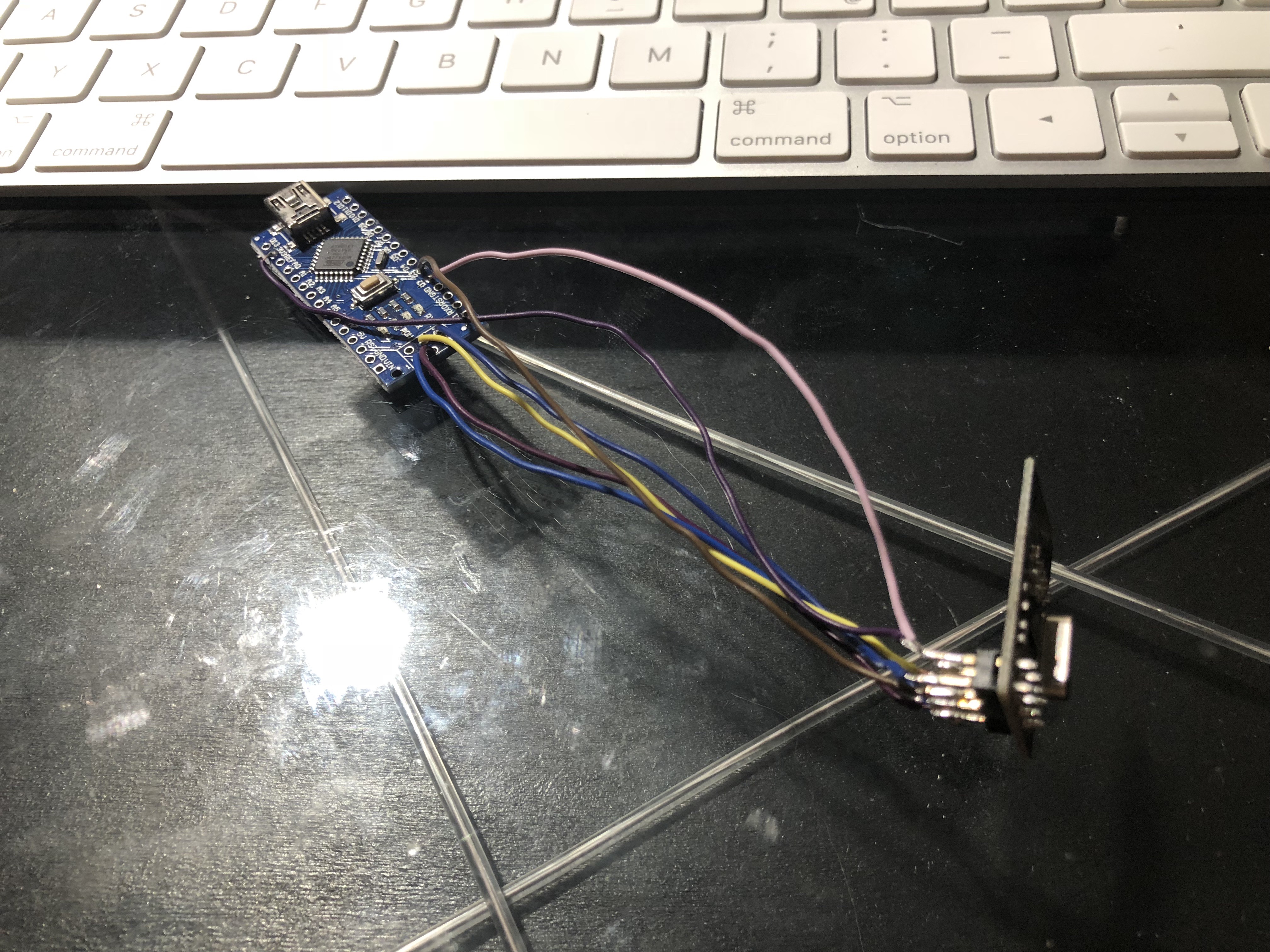
My main circuit is a bit complicated at the moment, so I am using two fresh Nanos to test the Code posted by MaB. If it works, I will implement it on the main one. If this all works, I could post my full code and shematics and somebody could order PCBs for everyone.
The code works but needs Debugging. If you turn the TX off the receiver keep the last throttle!!!
To use nRF24 reliably, add the power shield module to it.
For that reason I was thinking of implementing the ramp on the receiver side so if the throttle jumps in big steps (up or down) due to a transmission error, it would be softened by the ramp code. I also implemented a check on the receiver side, if there is no radio link for a defined time (700ms), the throttle is set to 0.
1 Like
I have a 1500millis timeout on the receiver but it has no effect… I need to figure out why.
How did you managed the ramp on the receiver? For first trials I will use a GT2B for reliability but adding an Arduino to smooth reactions was my first thought.