Mat how is your diy waterproof remote coming along? Have you tested it yet ![]()
On Monday I’m starting to design a DIY waterproof surfboard remote control as well.
1 Like
yes, tested in the water… the remote worked great and no water inside.
but i couldn’t get to to work through a bit more than 1 feet of water, so i had to bring the receiver above the surface.
My motor design is slightly under power and first try was with a kite wing and a very small board… so it was not picking up speed… and i ended up burning my amp-meter.
now in the process of making a bigger board and bigger wing…
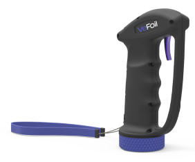
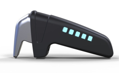
I came across this wireless waterproof remote from Radinn, a mfr of e-wakeboards, Details HERE
4 Likes
Hi @Alexander
Which hall effect sensor did you use in the 3D remote. Is it for 3.3 volts. I can only find a hall effect sensor for 5+ volts
I use the SS495a which is 5v but seems to work fine on 3.2v from teensy.
1 Like
Hi,
I used this one… it works perfect with 3.3V
https://sensing.honeywell.com/honeywell-sensing-ss39et-ss49e-ss59et-product-sheet-005850-3-en.pdf
Think it’s the ss49e from Honeywell. Bought it on eBay back then ![]()
1 Like
Thankyou. Your help is appreciated
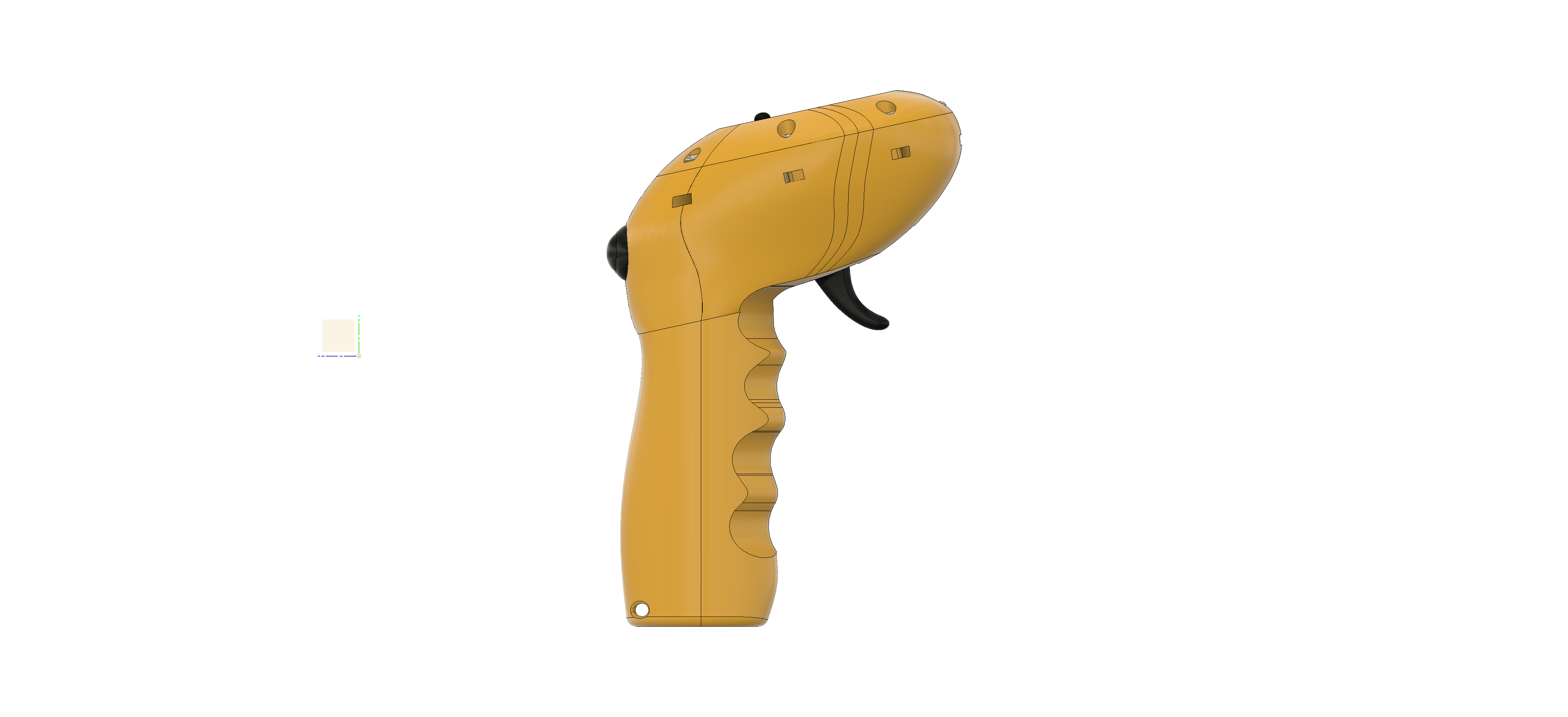
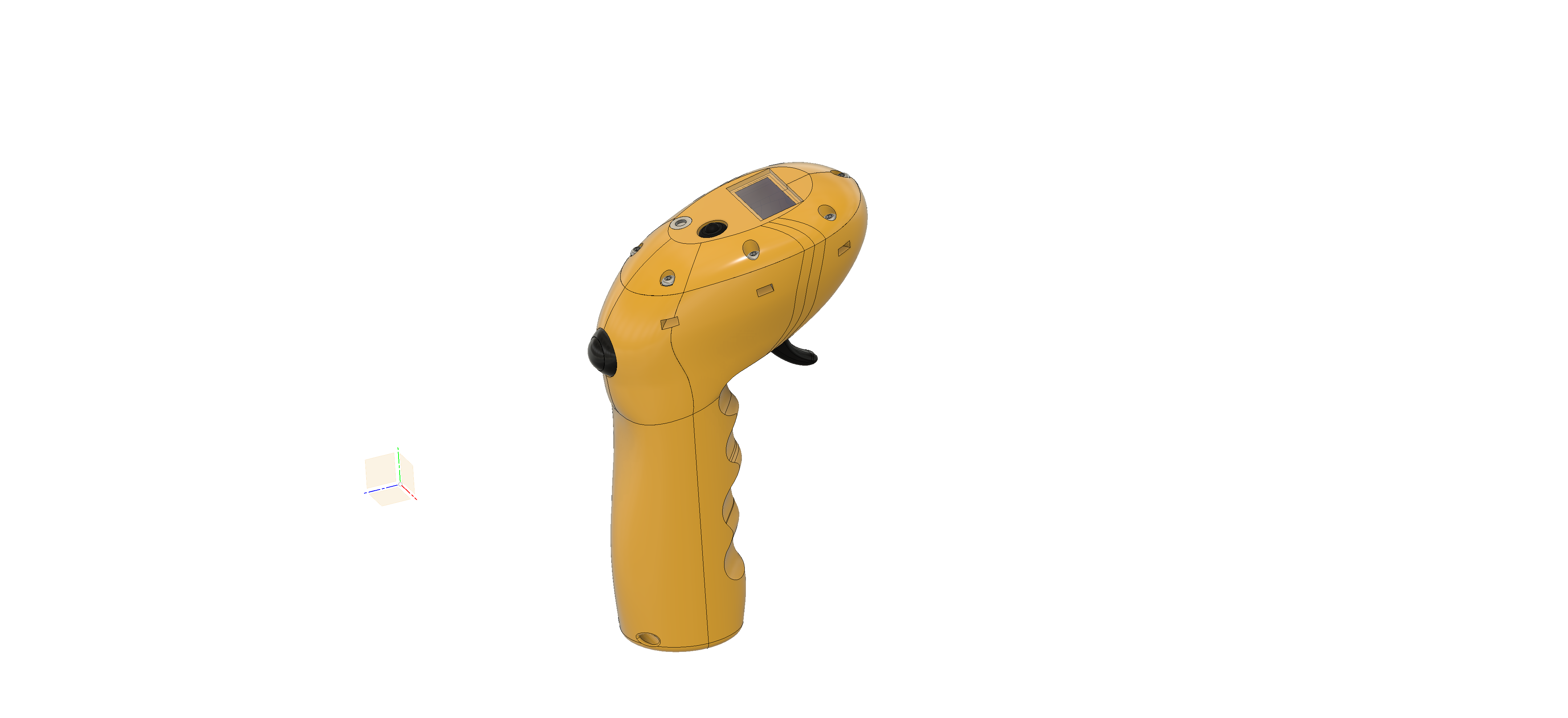
Just finished designing my waterproof remote. It’s on the printer now so hopefully it works as planned. huge thanks to @Hiorth for the trigger design, you guys are awesome. Using an ESP32 Dev board, 0.96inch OLED screen, IP68 Dead Man Switch and 18650 cell. Will also have LED battery indicator for the remote, Board battery indicator will be shown on Screen. Going to make my own On Off switch with a tac switch rubber cap and epoxy
5 Likes
I plan to do my remote a bit differently. When you fall, you are likely to grab the remote tightly, so you actually accelerate even more. I want to make it so that it stops the motor if you give it full power. Some rockclimbing belay devices have such a panic feature.
I want to add 3 waterproof buttons to the remote. Each with 2 switch levels (press down/ press all the way). One to activate the switch and the second one to panic stop it. All switches will slowly accelerate the motor to keep the load down and the acceleration predictable for the rider.
Switch 1 is for trolling about.
Switch 2 is calibrated for planing speed, so you can get up on your feet without jerky acceleration. Getting up is difficult enough. Try it on your floor!
Switch 3 is to get to cruising speed.
You could also add an override switch to adjust for heavy riders or experienced vs beginner.
I imagine that this system will be much easier to control and give you one less thing to think about. Hopefully the repeatability of the acceleration will make riding easier to learn. I used to fly glider planes and the acceleration at the start is always controlled by somebody on the ground.
There will also be an on/off button that activates my big relay. Like the egniton in a car.
All will be done with 2 Arduinos and 2,4Ghz modules. Module The arduino is great because you can easily add a ton of procedures that will be automated. Like battery management, temperature monitoring, anti spark and emergency stops.
@MaxMaker what switches do you plan to use? It is difficult to find a suitable ‘waterproof’ basic switch let alone a 2 stage one. I have similar ideas to what you are discussing around different speed controls, but currently are only using 2x single stage position push buttons.
Yes having a micro-controller, teensy in my case, allows for lots of extra features, maybe too many  . Let me know if you find anything suitable for the switches.
Sounds complicated. I like simple. You certainly want fine control over your speed at all times, e.g. when you are on a wave or when you want to do tight slow turns in the marina. I have tried many different remotes and right now I like the handling of thumb control the best. But that’s personal preference. Thumb throttles also look less like guns, you look a little less 007 but you also cause less panic. I think a cutoff mechanism at full throttle will make you crash more because you will accidentally trigger it.
1 Like
I never tried the efoil yet, but I wonder if the deadman is so necessary on the remote. It complicate waterproofing while adding potential failures… Maybe a safety on the board could work more effectively?
It complicates things, but we think its worth the extra steps to have safety features on both, to ensure no people getting hurt.
1 Like
Hello
I tried your code (transmitter)for arduino and when compiling a code “Fatal error: RF24.h: no file or directory of this type” appeared, can you help me on this small problem, in advance thank you.
I finally found, it missed in the bibliotherque of the program arduino the file RF24 master, thanks
Hi @philippe I have the same error code. Could you please share you working codes for the receiver and transmitter. Thanks for your help
Hello,
at first, you have to download the file “RF24-master.zip” (
do not decompress ), then to launch the Arduino program, then go to the tab “sketch” then in “include a library” then "add the library .zip “and normally it’s good, just take the files” ino "of Pacificmeister ,if you have any other question, I am available!
1 Like
Just trying out a new idea for a waterproof trigger mechanism. Think I will still go with my version 1 design and @Hiorth hall effect sensor trigger setup but wanted to try this out to see if it worked. Uses magnets each side of the shell with a lever connected to a potentiometer. This design is just a concept and isn’t ergonomically designed yet. The potentiometer isn’t glued in place so the lever rubs on the inside of the shell due to the magnetic force, works smoothly if held in place. Could also put some teflon tape in the channel on the outside to make things smoother. It works better than I expected though. There is a short video clip in the google drive link below
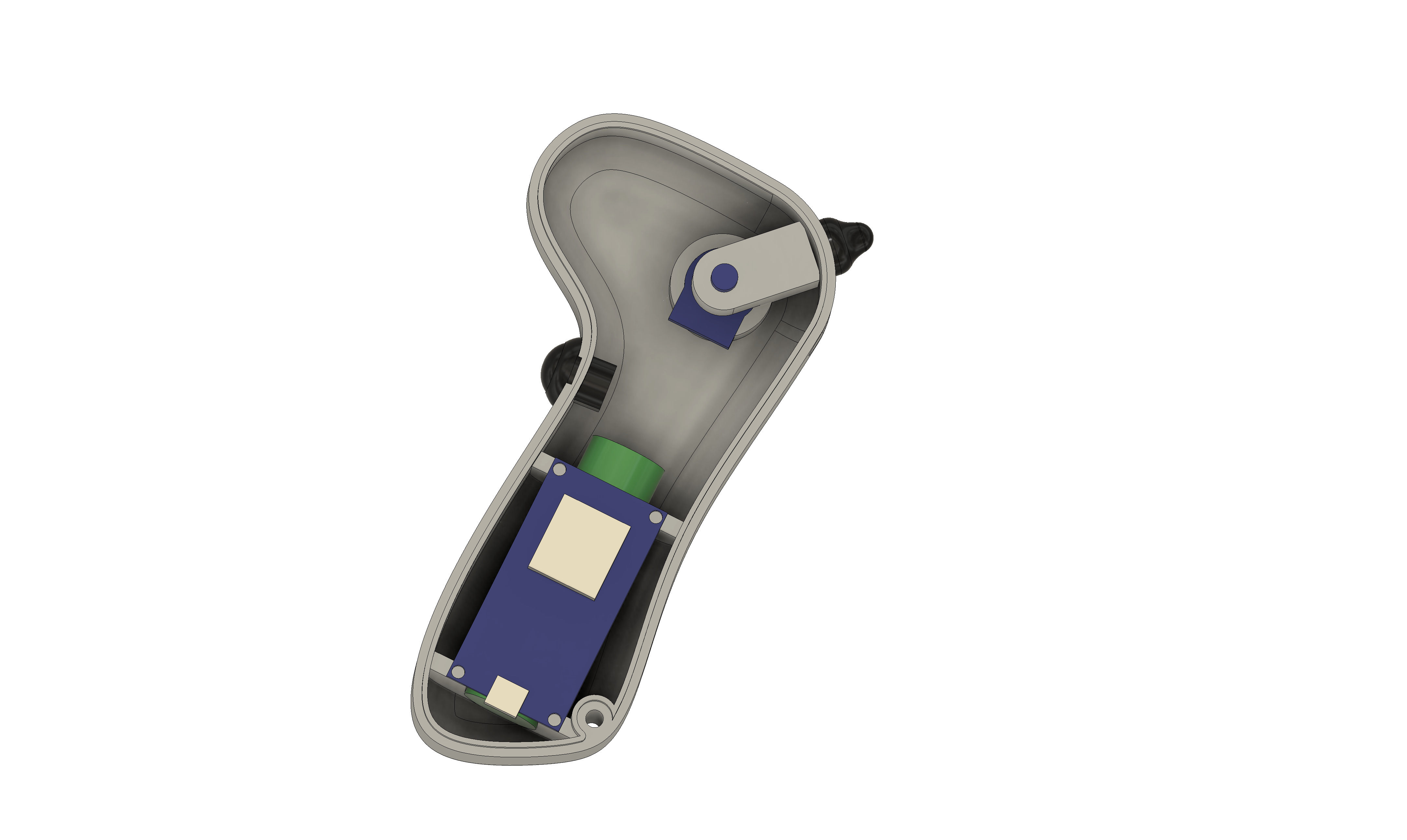
3 Likes
@pacificmeister @Alexander
I am building a Arduino remote and receiver using the same parts suggested in your post.
I hope this isn’t a silly question, but do the 2 RF24L01 modules need to be somehow paired with each other, or is it in the Arduino coding?
Thankyou for your help.