Thanks for the update!
My board length is around 340cm.
I can imagine there are reasons for this kind of design, could you please explain why you would choose it? Do you have experience with such design?
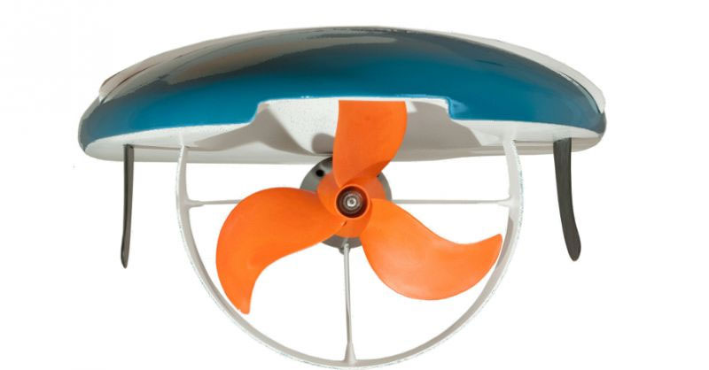
Here is a pic of a tunnel hull.
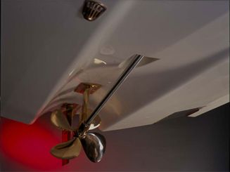
As you can see the prop sits a lot closer up to the hull. It kind of sits between a jet and inboard. It provides much better handling when turning as the prop stays more centered instead of shifting side to side like a pendulum. Waterwolf use this method on their boards too:
Your board is also incredibly long! It would be very interesting to see how short you can go and still get similar speeds but with much better handling.
1 Like
I have been considering a propeller tunnel hull om my motor surfer project. One of the advantages is the shallow draft. Another reason on bigger boats (inboard engines) is that the shaft angle can be kept more favorable in relation to keel line. In our application a duct can probably be integrated in to the hull shape rather easily, like Waterwolf. However my plan is to keep the motor inside the hull. I have no idea how prop tunnelwill affect handling/steering on a surf board, in some respect would imagine the tunnel would stabilize the the stern like a keel due to the denser water flow around the propeller, good or bad for turning don’t know.
Again if keeping as comparison bigger boat applications usually the propeller tunnel boats(at least those i have been studying) is usually on semi displacement application, inboard engines, and probably more usual in twin engine applications but also in single engine use, not many used on light fast crafts. Waterwolf is the only one have seen in combination with a duct so far. Hope mine will be the second one:) Otherwise will not copy waterwolf, its not according to my own vision.
PowerGlider will not have any issues with the shaft angle as the motor is outside the hull so the angle can be adjusted easily. Usually optimal prop shaft angel is very close to the same as horizontal direction of movement, this way not much lost energy. Often shaft angle is used to trim the hull higher but then you always lose some efficiency.
1 Like
Wonder considering the turnability, how would increasing the “V” of the bottom affect handling? At lest stability would probably be harder to manage, but would also turning be more easy?
F1 power boats are also classed as tunnel hulls. Then there’s all the other shallow hull race boats that use tunnel hulls. If you look at a jet drive boards they create a type of tunnel hill.
If you want to go the straight motor on board or motor in board route, loom at the most successful jet boards on the market and look at how to adapt them into using a prop drive. There’s no reason to try completely reinvent the wheel. Rather adapt and improve.
Yes, the F1 and other similar catamarans are classed tunnel huls, there the tunnel does not touch the water and the idea is to generate aerodynamic lift to minimize the wetted surface of the pontoons, this to increase speed. What we are talking here is usually refereed to as “propeller tunnels” or “propeller pockets”. Here an interesting article about the subject.
It is true that the jet propulsion gives a pretty good hint about the principle. In case inboard motor due to we have a much bigger diameter propeller, some modifications of the principle is needed.
What i think is very interesting is the awake design. Looks like a hybrid between Jet, Ducted propeller and propeller pocket. Motor is binged down to get the shaft almost straight.
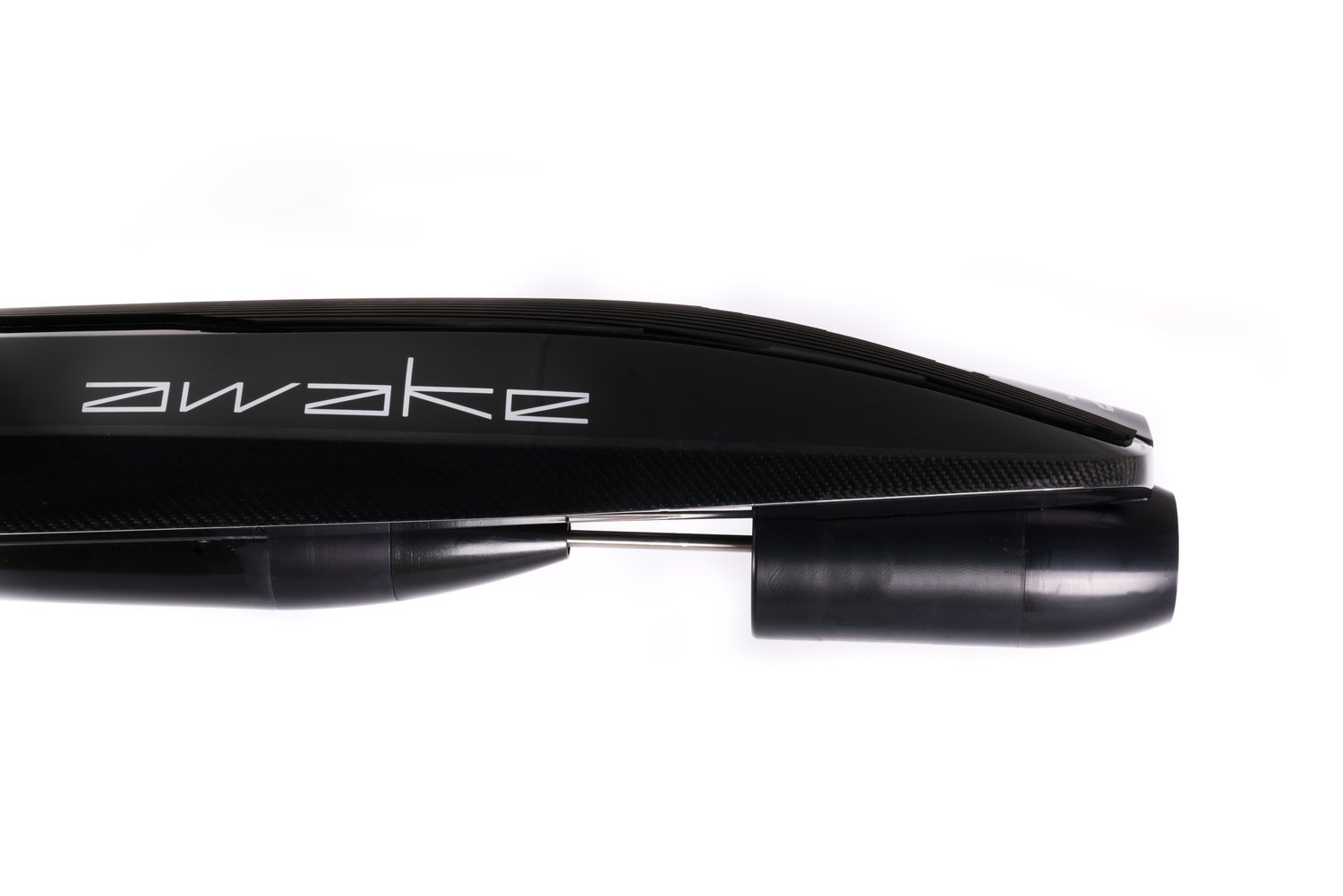
2 Likes
Hallo PowerGlider.
Job well done, congrats. One question please. I originally assumed that the water between coils and magnets would start to boil du to the magnetic and friction force. Do you have any long time testing results?
Kind regards
Harald
The very first design (which i did not describe in this thread because it was quickly destroyed) had no openings in the bell at all and a fully covered stator which lead to overheating and cooking water indeed. All later designs have some sort of opening in the end bell to ease waterflow.
I started a new thread regarding the 63100 which has a completely closed bell. In this bell i drilled two small holes on the outer diameter of the end bell to have some water flow.
Here you can find the fusion file:
Maybe its not the optimal position to locate these holes and you have better ideas how to locate them for optimal cooling and low friction. Of course there is a slight risk of cavitation. To reduce this risk, the inside of the bell is filled with epoxy between and covering the magnets so it is basically a cylinder rotating over the stillstanding jagged topology formed by the stator.
1 Like