Dude that looks SO FUN!!! So jealous…I have my propeller and drive shaft now 
Guys this is so much easier to watch than to make!!!
Dude that looks SO FUN!!! So jealous…I have my propeller and drive shaft now
Guys this is so much easier to watch than to make!!!
Here comes a long large version of my 2018 videos in mediterranean sea:
Please tell me if the download works.
I have posted a 2nd smaller version around 200MB.
Can you reach it?
Have Fun!
Works, but it says only for today.
Nice video!
Didn’t work for me…
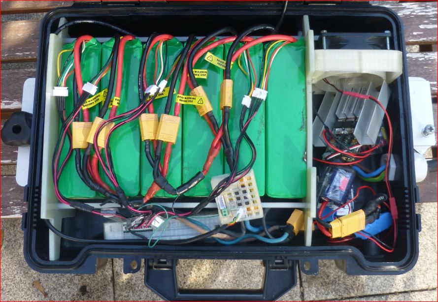
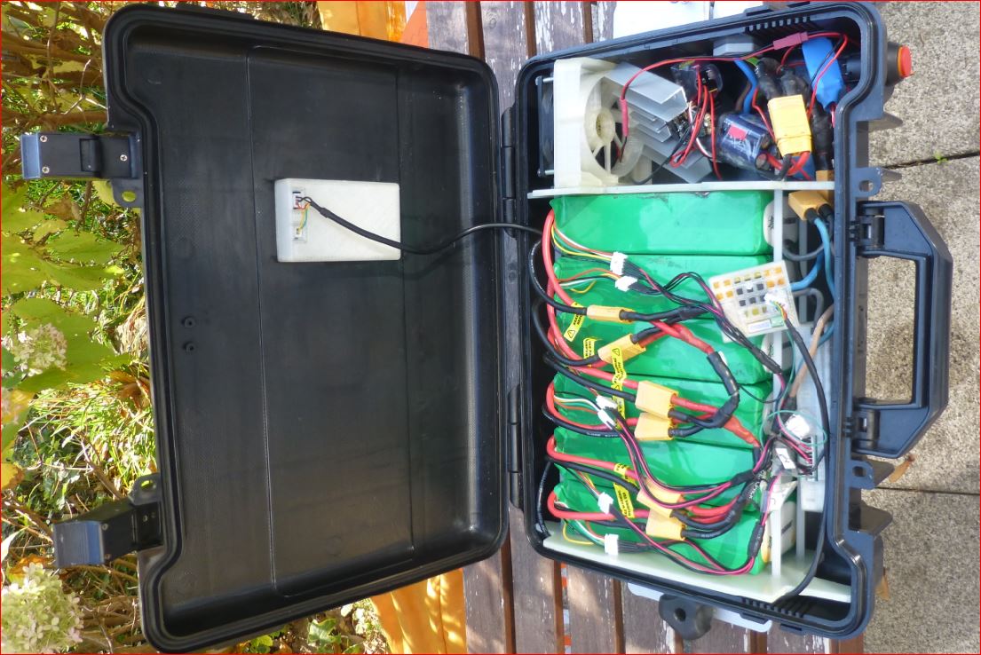
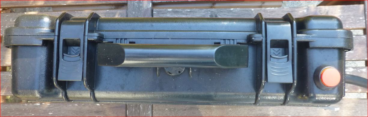
Nice board and good video! How big is your box? (Can you post a photo of the inside?)
Good idea to use the cutout for mastbase for fasten the box!
Thank you very much! Awesome!
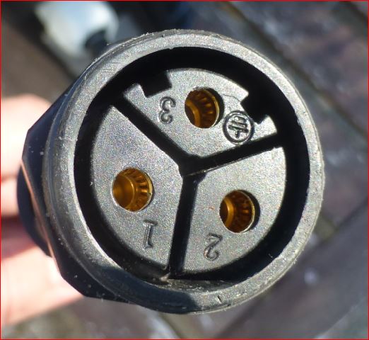
Where can I buy such a connector?
I can sell you one (inside europe), please write pm.
What is the current rating per pin? (sorry if I overread information on this connector)
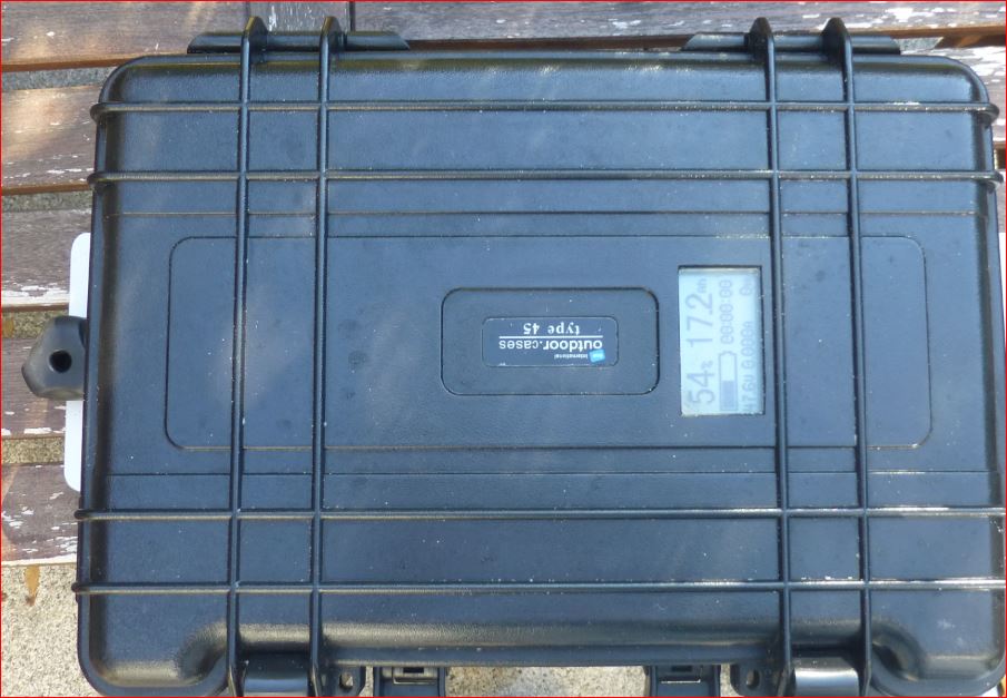
What size box is that?
Its an Auhoa AH-M29-3503MMZ01122 , nominal rating 35A DC or RMS per pin, 4mm diameter per pin, max 6mm^2 solder connection, 11-15mm outer diameter of cable. I combine it with rubber cable.
The box is a B&W International type 45 black leer/empty.
Lets make a small rough calculation about the force F_w of a torpedo style body:
We have the outer diameter of 0.063m, a roughly estimated c_w of 0.3, ro is 1013kg/m^3, my velocity at the moment is max 5m/s.
wikipedia says:
F_w = c_w * A * 0.5 * ro * v^2
F_w = 0.3 * (0.063/2)^2 * pi * 0.5* 1013 * v^2=0.473*v^2
With 5 m/s: 11.83N
With 10 m/s : 47N
So the power is Force * velocity:
P_w = 0.473 * v^3
5 m/s: 60W
10 m/s: 470W
How do you get so high values? Am i missing the friction?
Also i do not understand your estimations about surfer and the power human develops.
If i remember correct, i can run 20m of stairs in 40s. So its 0.5m/s with a force of roughly 750N, this makes a power of 375W.
If i look at the surfer, there is a forward component force on the boards mastfoot and the human, lets assume 400N, at a speed of 10 m/s, so its a power of 4kW. The surfer does not generate any power by holding the sails forces.
With the setup you see in the vids and pictures i had a reach of 11km, at a battery power between 1.7-2.2kW, the oscillation you can hear in the last 35 seconds. This oscillation is between 60 an 80% dutycycle with a VESC 4.12 tuned for low powerloss pcb and very direct cooling. It is caused by thermal protection. Unfortunately the two shunt VESC with its fw 3.39 has a turbo gap between 60 and 80%. It is frequently triggered by the thermal cutback. I use BLDC mode and DC control by PPM. I have opened the limits to 100A phase current, 80A battery current and abs hw limit to 200A. In the beginning, the power can be up to 2.7kW, even 3 i have seen for short time, and it feels good and straight for the job.
I need a new cooling system to outside of the box.
Sorry for the confusion but I was comparing the waterwolf with the 3.5 inch diameter hub with a half sphere nose which yields a .5 coefficient of drag
I also have researched this a lot with human powered hydrofoils such as this one IHPVA - International Human Powered Vehicle Association
and the power to launch is 400 watts and 200 watts for sustained planing/flying
The Manta5 is an excellent example of this
I tend ot come at engineering problems in a very counterintuitive way sorry ![]()
So, i need a new cooling system for my box with integrated VESC. I made some studies in fusion and now i ordered an alu cooler PR158, 100mm long, 159 width, Fins 11mm high, back 4mm.
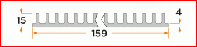
https://www.alutronic.de/produkte/standardprofile/profile-einseitig-verrippt/114/pr158
This cooler i want to mount to the outside/downside of the box, so the fins point outside and downwards. I make a hole of e.g. 40x80mm in the box bottom. Into this hole i put a copper bar e.g. 40x80x10mm and screw it to the alu cooler. I glue everything from the inside, so there is a thin barrier of glasfiber and epoxy on the copper cooler inside the box. Onto this i mount a new designed VESC, with the PCB on the Epoxy on the copper.
The Alu fins outside are wetted by water as you can imagine from the videos. If the water flow is too low in general, i could mount a nozzle in the dagger board space to feed some water via a hose onto the board and the fins of the cooler.
What is the benefit? There is no pump. There is no water inside the box. There are no openings for water in/outlet. There is a kind of water cooling and material transport, because the cooler is wet. There is no box separation between battery and ESC, no additional connections.
The electric isolation between inside and outside of the box has to be realized by the coating of the inside metal components.
What do you think?
I planned to do the same thing, but didn’t do any calculations or thinking regarding heatsink size. But I forgot that there isn’t really space on the bottom due to the foil, I would need to put the esc way forward. So I thought a heatsink on the top could do the trick too, good airflow is provided.
Material flow is the trick, especially water below 25°C.
Because I am uncertain about the amount of heat dissipation I wanted to dry test motor + ESC with different cooling solutions to see which ones are suitable and which aren’t. But on the other side I want to get going quickly and haven’t found a perfect cheap way to load the motor realistically without putting it in water. I want to use the Freefly Arc200, which has very promising and believable current specs:
Max peak phase current: 200A
Continuous current with little to no heatsinking (hot-side facing upwards and unobstructed): 60A
Continuous current when bolted to a typical EV aluminum chassis: 100-150A
Continuous current with infinite aluminum heatsink or water cooling, and forced air cooling on phase wires: 200A
https://freeflyrobotics.com/products/arc200
That makes me believe that it is enough to bolt it upside down to a aluminum heatsink on top of a aluminum box.
Hi PG
I spent a long time trying to find this link as I found it on my work laptop
Please let me know what you think of the final summary at the en of the video with regards to power requirements
Lastly, I feel the propeller/mast configuration is absolutely ideal for a powered efoil and for a powered surfboard
Best regards
Peter