Hi @powerglider. Did you have a chance to test your new setup? Thrust and speed? Will appreciate your feedback on the alien 100kv motor (powerglider motor).
What is the fin type you have used?
Many thanks!
Hi @powerglider. Did you have a chance to test your new setup? Thrust and speed? Will appreciate your feedback on the alien 100kv motor (powerglider motor).
What is the fin type you have used?
Many thanks!
Hi there,
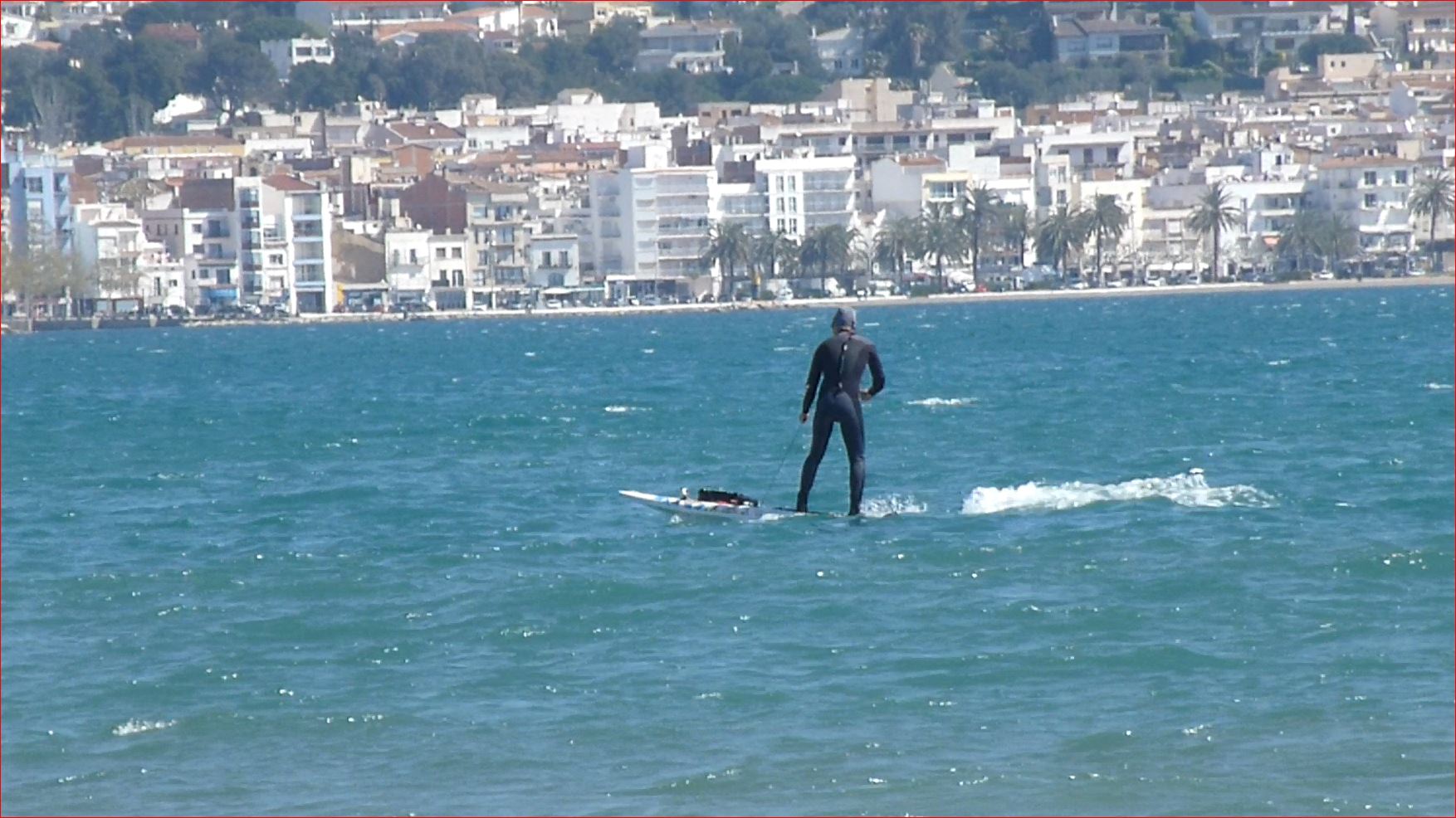
yes i tested it for some minutes until the battery box became untight because of a mechanical overload to the cable. As it was in choppy sea with strong wind it is hard to judge it.

The fin is made from high quality glass fiber, US/standard fin box. You can find high quality easily today, because a lot of windsurfers have grown old and sell their old but high quality equipment for peanuts.
Great! Thanks for such a prompt update!
Sounds like there is a room for bigger prop to get more power from the system ( unless it just became more efficient comparing to the old setup). Interesting to know the speed of the board, can you measure it next time? (Can be done with smart phone, taken with you to the ride).
Good luck and awaiting for new updates
Maybe i should try outlet vanes.
As outlet vane? Since intake is kinda done by your fin and prop closure supporters.
Can someone recommend an app for android for recording the GPS data with high resolution? Is GPSlogger a good solution?
I used runtastic, it showed max velo of 13.4 km/h. At 1.7-1.8kW. We drove around over an hour with a standup paddle windsurfboard and the Boosted board. We tried some towing also, it was hard to hold the rope.
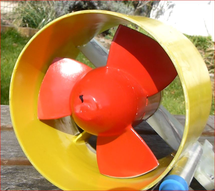
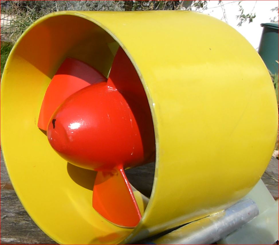
Its a little bit strange: If i take the pitch of the prop and the RPM, the props velocity without slip is around 30km/h. The inlet diameter of the duct is 160mm, reducing to 140mm at the outlet which is a factor of 1.3. Divide 30 by 1.3 is 23km/h. 13/23=57%, so the slip is higher than expected.
I could not mount the old drive system, because i was not able to open the nut of the cable plug by hand, so i was not able to test it to compare directly.
Any suggestions how to proceed? Higher pitch? Higher Kv? Vanes?
do you get the correct rpm? on boat prop i read that the best working part is between 80-100% of the diameter, may be cut this one too much ?
the prop on your first set up is the same ? it looks about 160mm right?
cutting: efficency loose +duct +slip = 57% why not ?
if you use an another boat prop with higher pitch you will need to cut it too …
Hi @PowerGlider Can you please share your design for the motor mount on the fin and the prop closure and spinner cap?
I would like to make the same setup (as alrady mentioned) and try different props and SK3-149KV motor as well.
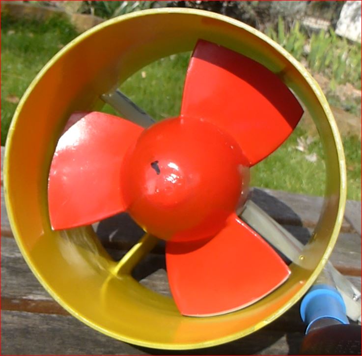
I think the speed of 14Km/h with 1700wt is reasonable so in order to get more power and speed it will require more prop pitch, keeping the same diameter of enclosure and number of blades (which are 3)
No. Powerglider setup is exactly targeted to solve the hitting problem, since the motor is open to the water after it is coated with epoxi. So water touches and flows through the motor. My hope also that in your setup the prop wasn’t optimized. Anyway I will configure the ESC to limit the current to about 80a not to go over 3000wt.
I just need powerglider motor mount design on the fin and the prop enclosure to print it out and try
Hi @Antonbit, great that you and @PowerGlider are experimenting with wet outrunners. I did a similar test with a too-small motor a while ago and I am happy to share my Fusion designs if that’s helpful. Let me know. See details here: For who try/have tried direct drive with outrunner - #3 by pacificmeister - Propulsion System (Motor, Gears) - FOIL.zone. It was the simplest design of everything I tried or have seen since we don’t have to deal with waterproofing, messy heat paste, etc… (aside from the motor epoxy prep, which I skipped). Hope you guys get this running!
The RPM is going up directly at standstill, no problem, the electrical system is underloaded.
The old setup was with 170mm inner duct diameter.
I think i will proceed like this: I have two 6384 100kV PG spare motors, untouched. I will rewind one of them for higher Kv, use it for the new setup, and use the 100kV from new setup for the old setup which was always overloaded.
I also have 6384 130kV which is in reality only 123kV. I could also give a try with this 130kV stator on the new setup, but the difference is not so high, and the efficiency will be lower because of reduced length of the usual stator.
By this i would end up with two better fitting setups which i can use depending on the situation.
Only question remaining: Which Kv for the new setup? If i choose 200Kv i do not need to rewind but only to open some winding head and reconnect.
That would mean i have 72 instead of 36A at 13.4km/h and with a limit by the VESC and motor cables of 90A there is not much headroom.
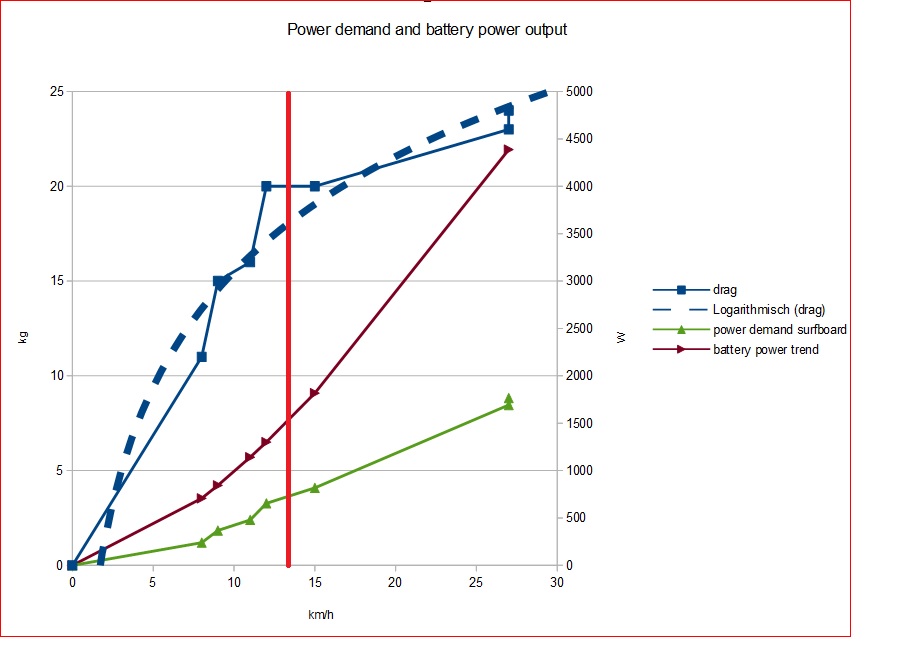
Lets have a look at this diagram once more:
I modified it, focusing on the surfboard and its power demand and my observed battery power and some assumptions:
Hi @powerglider. It is interesting analysis. Does it mean that the surf drag is lower in high speeds? If it is so why the required power is razing faster vs speed?
Can you explain the diagram?
What is the difference between “drag” and “power demand surfboard” ?
How can “battery power” be lower than “drag”? are you decelerating? i guess it should be equal while having a constant speed?!
I did try to understand the diagram myself yesterday eveneing, here is what I assume to be shown:
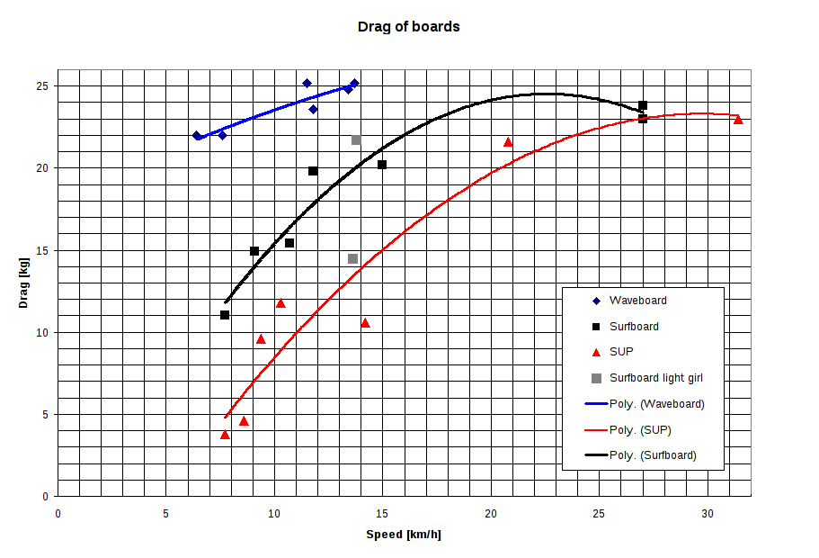
The dotted drag kurve is @PowerGlider’s assumtion of a logarithmic function for drag vs. speed. The blue measurement points are the values for Drag vs. Speed from the original diagram. Those values are drag forces (in kg on the left scale). The bright red vertical line is his mesurment point he described in an earlier post. The power demand surfboard curve appears to be calculated from the drag curve and uses the scale in Watts on the right. If you calculate the power from the drag interpolation in the original diagram ( Power = Force * (distance/time) and converted the drag to Newtons and the km/h to m/s) I get 589W for 18kg@12km/h and 1090W for 24kg@20km/h. This matches the green line for me.
@PowerGlider, it would be very kind of you to release your spreadsheet. This makes it easier to understand how you arrive at your conclusions. I can however understand that this is quite an effort. My own spreadsheet is quite ‘without structure’, so cleaning it up for sharing it would be hard.
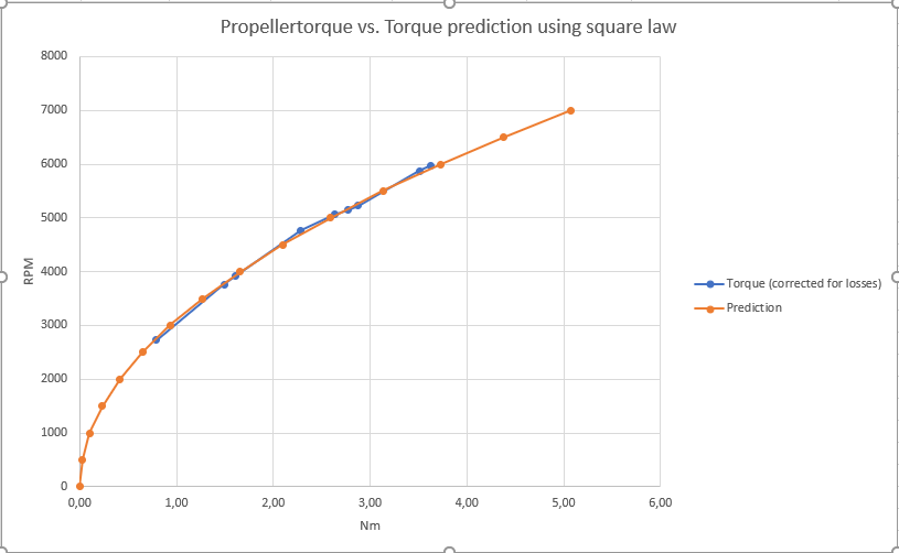
Anyway, on the topic of missing motor phase current dependent on speed. I think we are searching for the same basic information here. I formulated it as drop on propeller load(=torque) when the vehicle speed rises. As phase current is pretty much dependent on load torque I think we are searching for the same information. I’d love to have a model here. In other words I would like to know how the follwoing graph changes with vehicle speed.
Hi
it is a lot of work to extract the correct parts, because i made such a lot of modifications in the design process. I do not want to release the complete history, it is a mess. Additionally i adapted some parts by hand after printing. Would it help if i release some stl files i exported for printing?
There are big uncertaincies in my graph. The original measuring data is instable, and the assumptions i made are optimistic. I used my measuring point for 13.4km/h at 1700W and adapted the battery power graph to be similar to the power demand graph, than scaled it by factor 2.4. Very simple approach.
Time to get some books.
STL files are also very helpful, since I have the same motor as yours and I would try different props with this setup based on your STL files.
