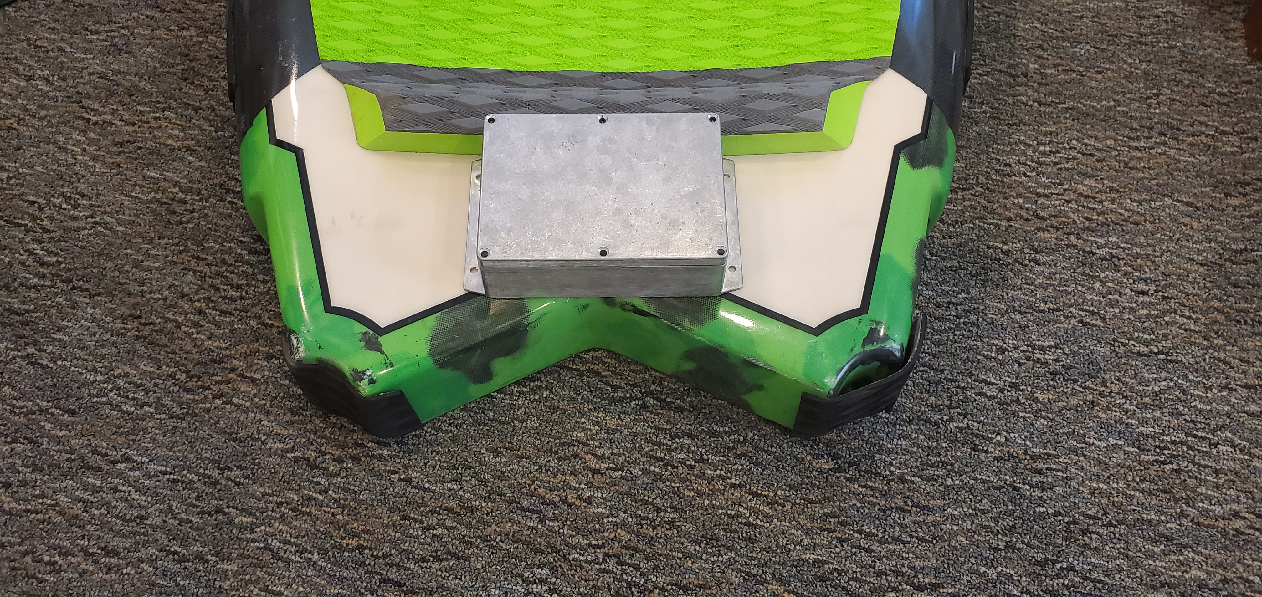
For the motor controller enclosure we are using a Polycase AN-06F. It’s an IP68 rated aluminum enclosure with dimensions 6.73 x 4.76 x 2.17 in. It has a flange for easy mounting.
1 Like
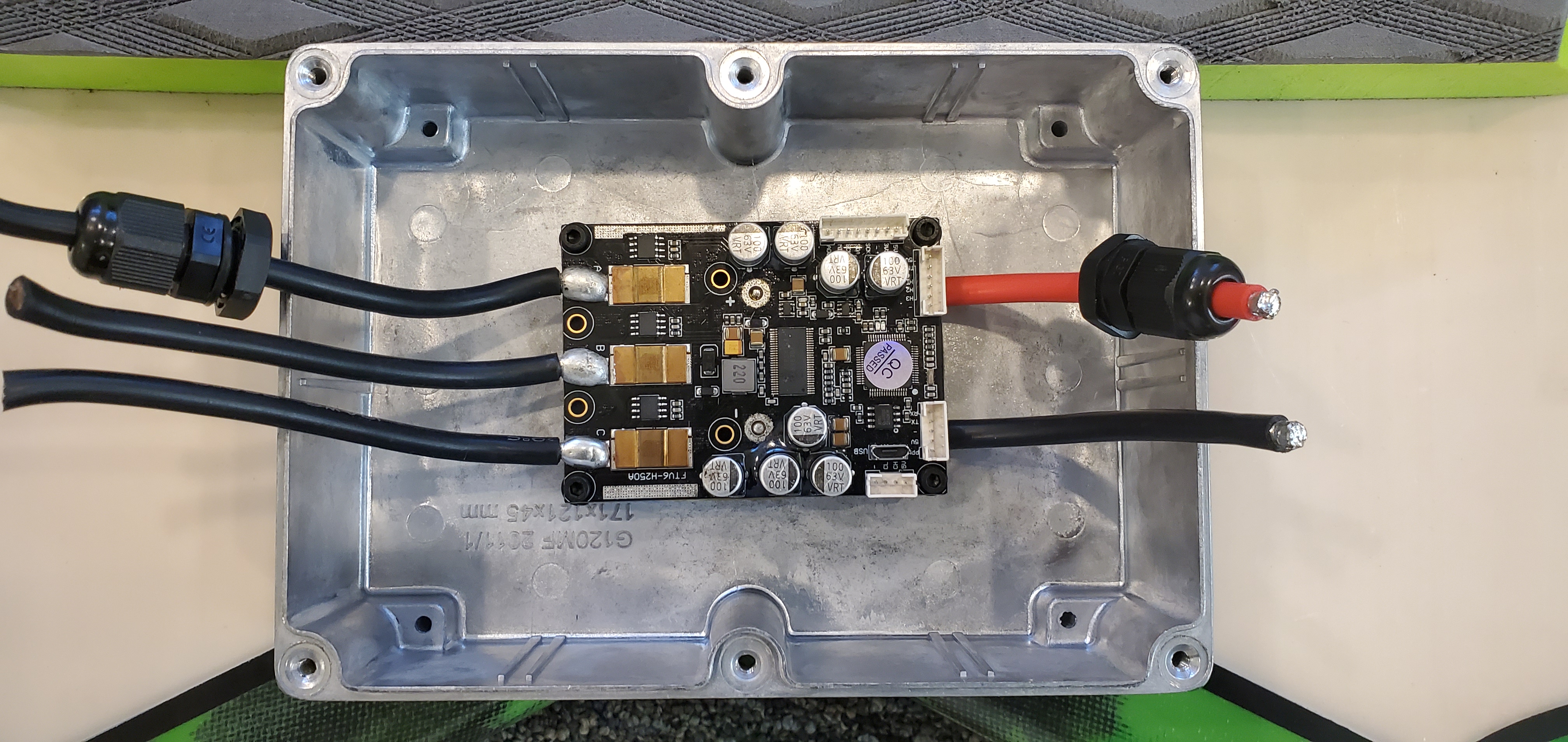
As mentioned in the introduction post we are using a VESC motor controller as the primary academic purpose of our build is data collection. We are using an implementation of the VESC6 by Benjamin Vedder manufactured by Flipsky with an advertised rating of 200A.
Note: I purchased this VESC during the planning phases of the project. Some time has passed since then and Flipsky now sells the 200A version in a potted enclosure with water cooling ports. I suspect it is more robust. In an effort to keep it simple we will implement passive cooling.
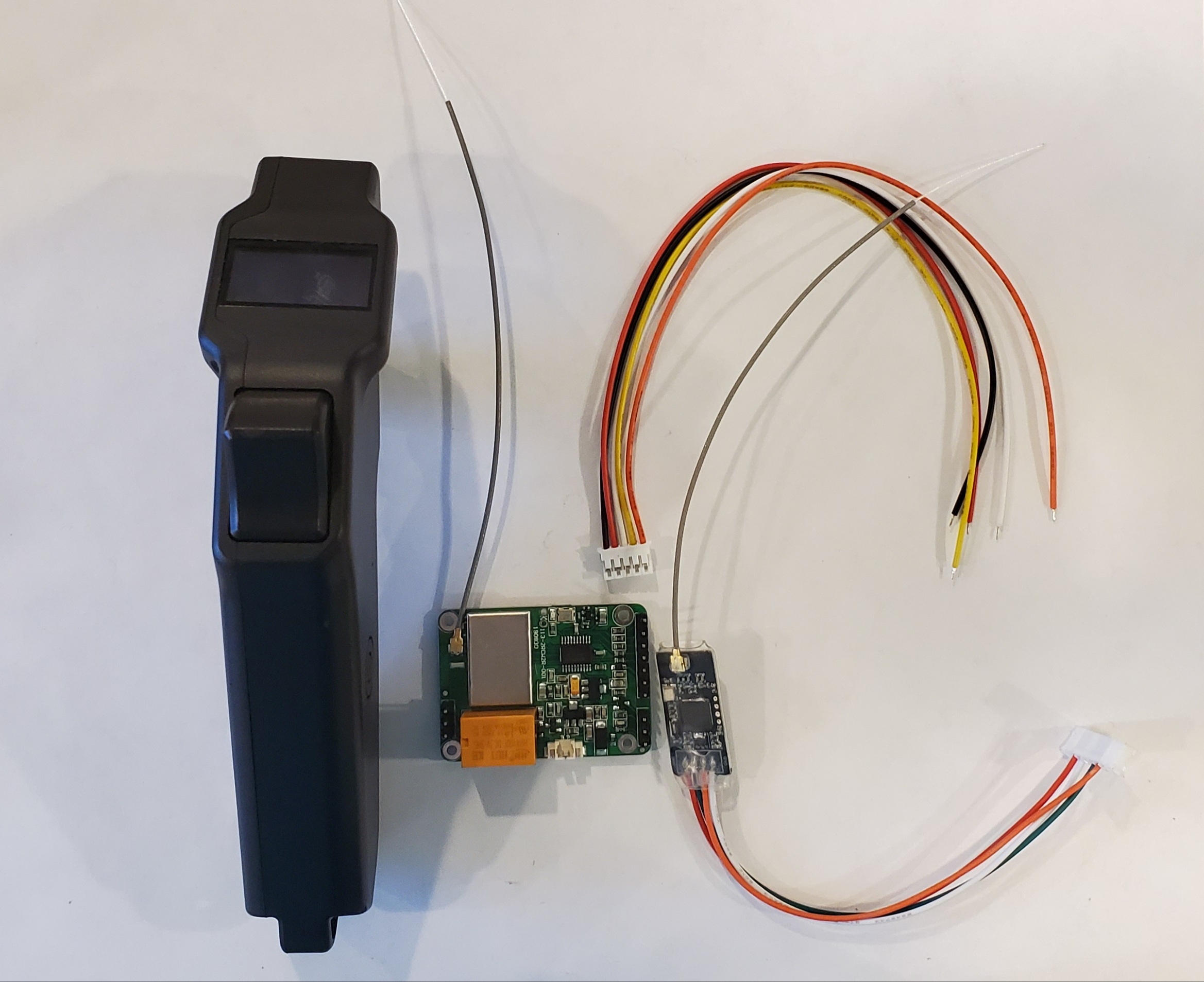
We are using the Maytech V2 waterproof remote with firmware v1.13 and the Flipsky VESC6 Bluetooth module for our radios.
The Maytech remote allows us to view RPM and battery voltage on the display without occupying the VESC communication channel. We are able to get these values by jumping a motor wire and battery wire directly to pins on the Maytech receiver PCB. We also purchased JST-PH 5 pin connectors to make a small harness. Note: JST-PH is smaller than Li-Po battery balance leads.
The Flipsky Bluetooth module for VESC6 allows us to connect an Android phone running Vedder’s Vesc Tool app. We can display these values to the rider while datalogging via the phone mounted inside the battery enclosure.
The Maytech remote features two accessory relays (exciting!) for whatever you would like. We will not be using the 30A relay for a water pump (even though its ideal) because we are keeping it simple. Did I mention we are keeping it simple?
Hey my names Dave I’m a mechanical engineering student on the east coast would definitely like to talk about refining your design. My schooling combined with yours can come up with a great refined system.
I have extensive experience in FEA and fluid analysis using CAD programs. I also have built Multiple surfboards from scratch as I live near a surf supply ware house . One thing I don’t have experience is in the electrical aspect. I do have experience in data collection and processing for electrical systems that relate to mechanical world.
Have you set a budget for this project?
The goal was $3,000 and that ship has sailed. The final components that make it into the board will likely meet our $3,000 goal however. It is often overlooked in these builds the expense involved with the aggregation of little parts like adhesives, connectors, wires and enclosures. Tool access is also often overlooked. We were fortunate to receive a grant award from our university to cover the big stuff. Thanks for the interest.
1 Like
Still 4K under the cheapest on the market. Did you guys buy the board and foils aswell. If so approximately what percentage of the total cost was just electrical components?
It’s not done yet. 
Will be cool to see final design , good luck on your guys presentation.
Thank you. Keep an eye on this thread as I’ll be updating it frequently up until the conference. I will convert this to a personal project after the conference and continue over the summer.
1 Like
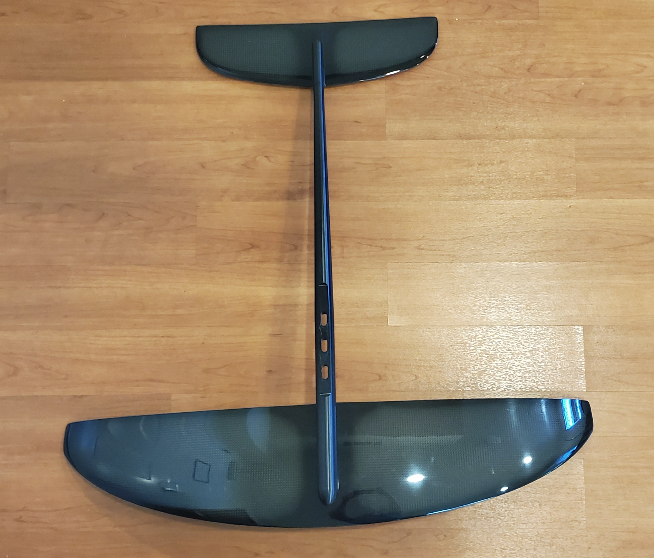
That board is beautiful must be really thick to have 145liters on that short length!
Yes sir! At 4.5" thick its asking for an electronics cavity to be cut. Learning from past projects, don’t ever make your version 1 complicated. Keep it as simple as possible! I’m using Velcro to secure the battery and ESC enclosures.

Simplicity should not come at the expense of safety! I am using an EL-AN200 200A fuse able to prevent flashover up to 58V DC. The fuse should be the weakest point in the system by design. I think with a fuse of this size the Li-Po XT90’s would slowly go first. I do believe I should have gone for the 150A version especially with a 12S 12Ah Li-Po back rated at 12C (144A cont. max rating) this fuse is really only good for protecting against accidental shorts. I will install this fuse holder and swap the internal fuse to a 150A.
Can you send a link to where you got this fuse from?
I only seem to find ones rated for 32volts…
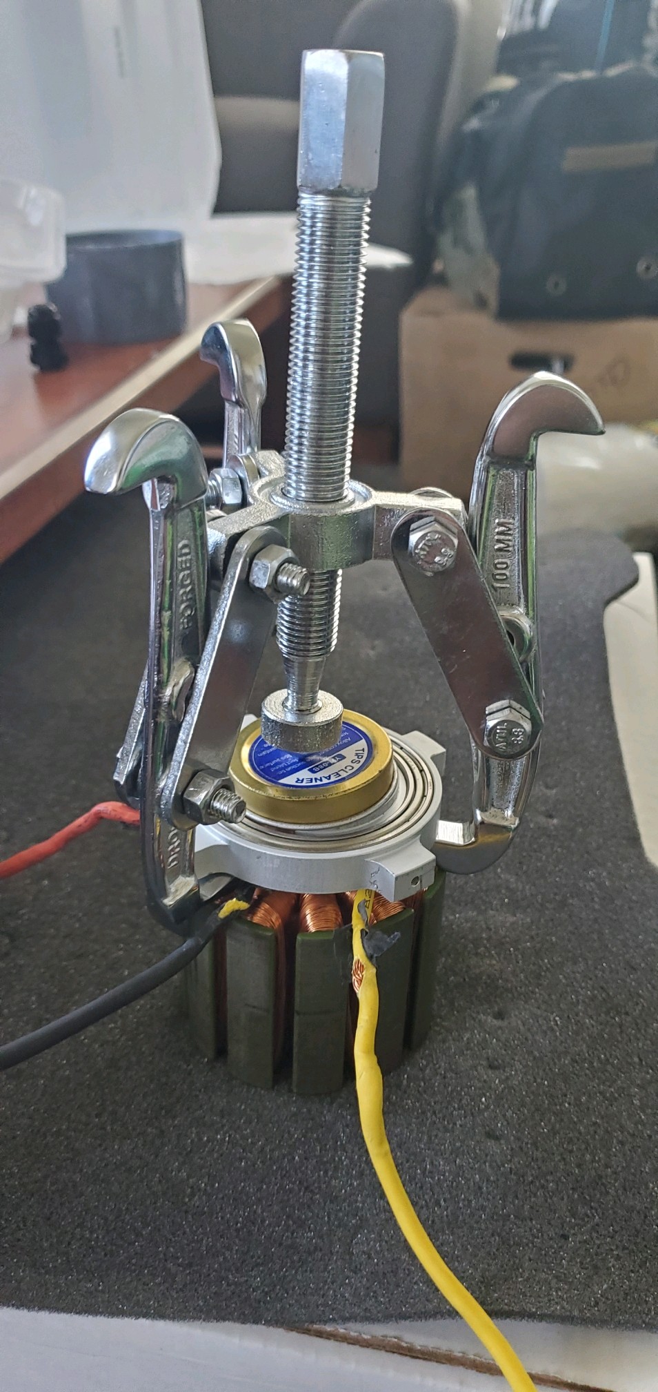
For the motor we are using an APS 80100 80kv. I am getting ready to paint the stator with epoxy. The first step was to remove the main bearing. It was tricky because there is a smaller bearing in the center. I used a cap to span the bearing and put the load onto the stator core. It worked well after the cap crushed down; the shaft bearing looks unaffected.
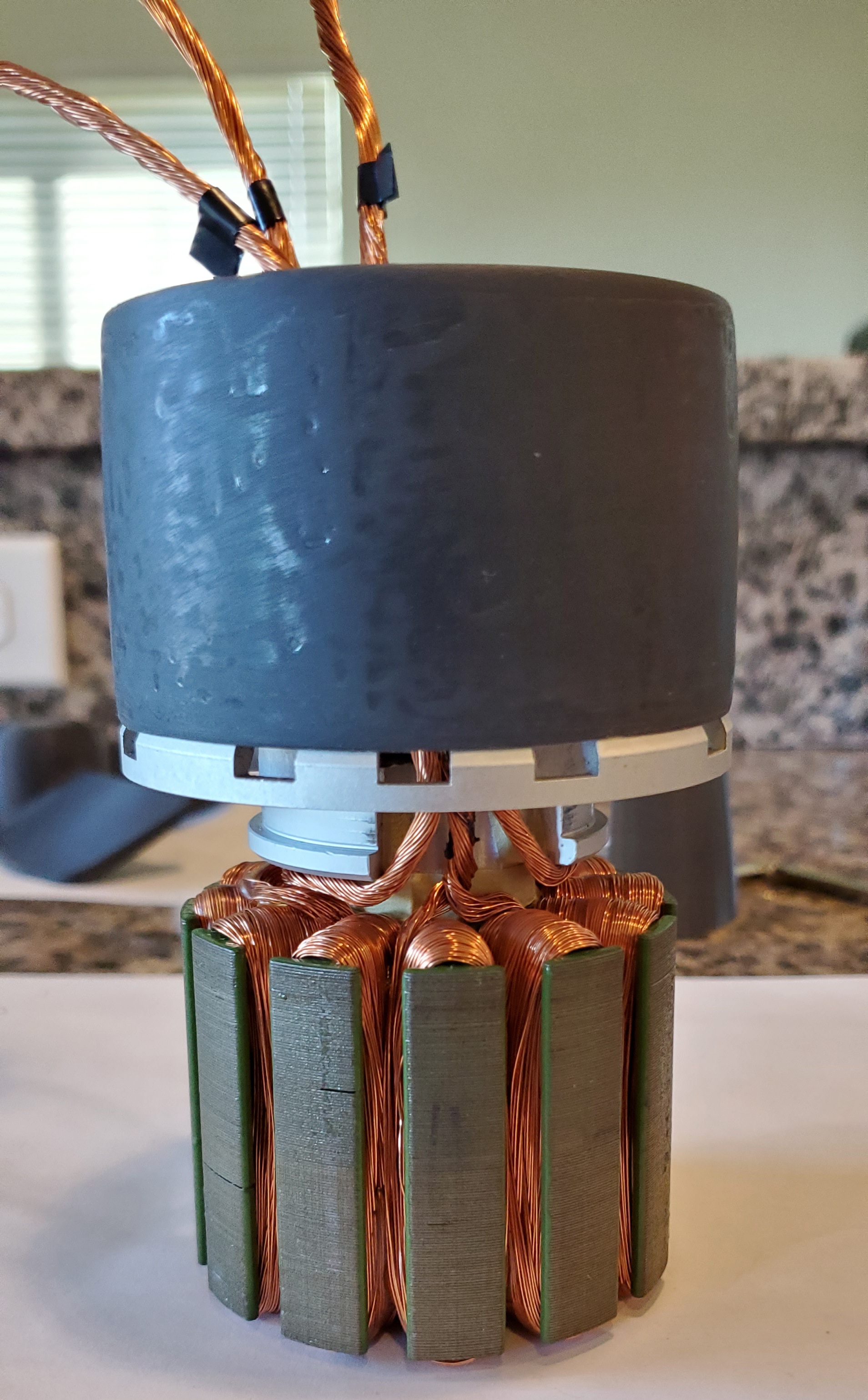
Today I prepared the stator for epoxy. I removed the wire insulation, covered the shaft bearing and threaded holes with e-tape and marked how far along the wires should have epoxy using the rear mast clamp.
The Maker Lab at SCU drilled holes in the motor cap for me to allow the wires to enter the clamp. They also 3D printed the mast clamp by V_S from the Volker build.
I will be filming the epoxy painting process for the stator and clamp parts. Stay safe and stay tuned!
1 Like
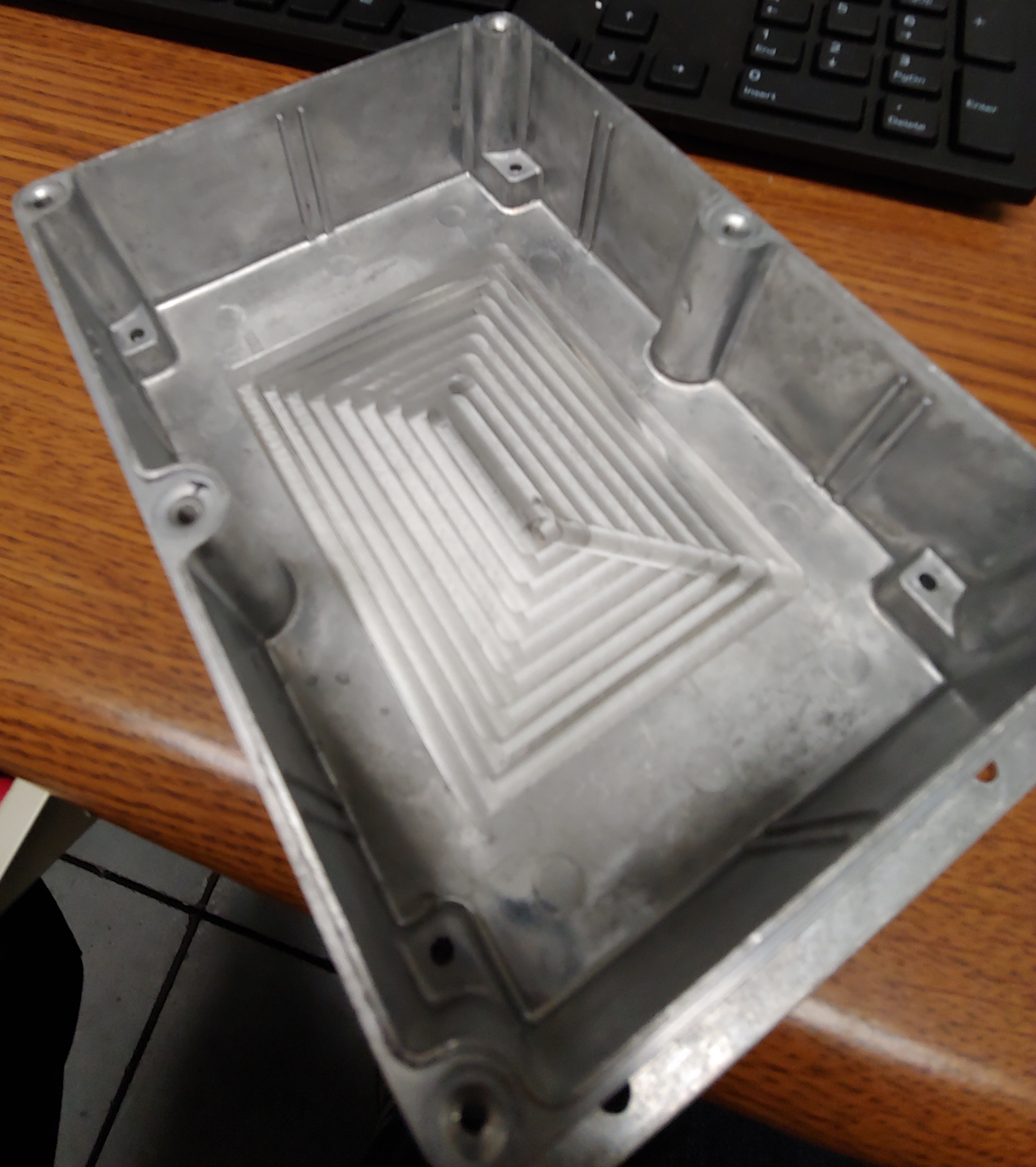
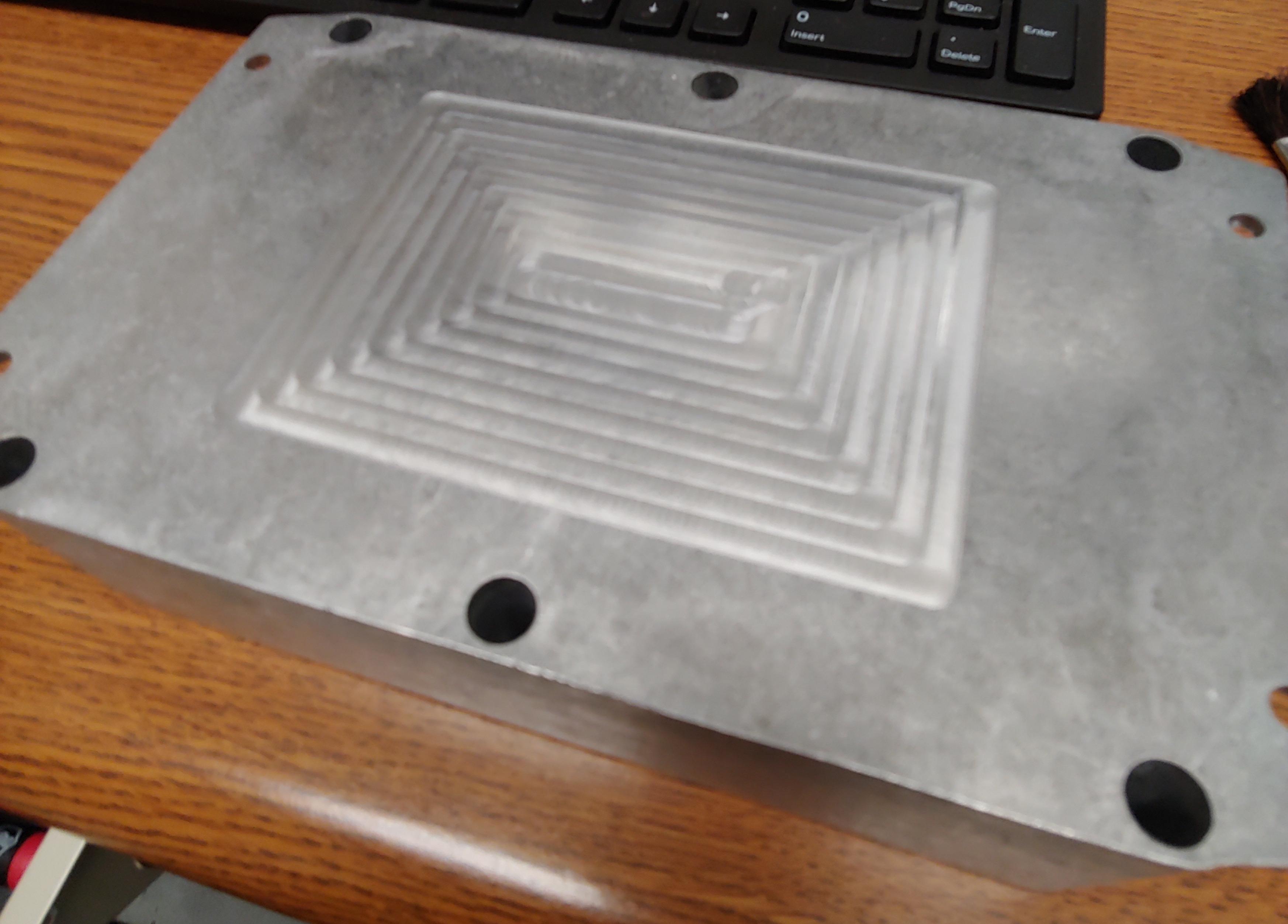
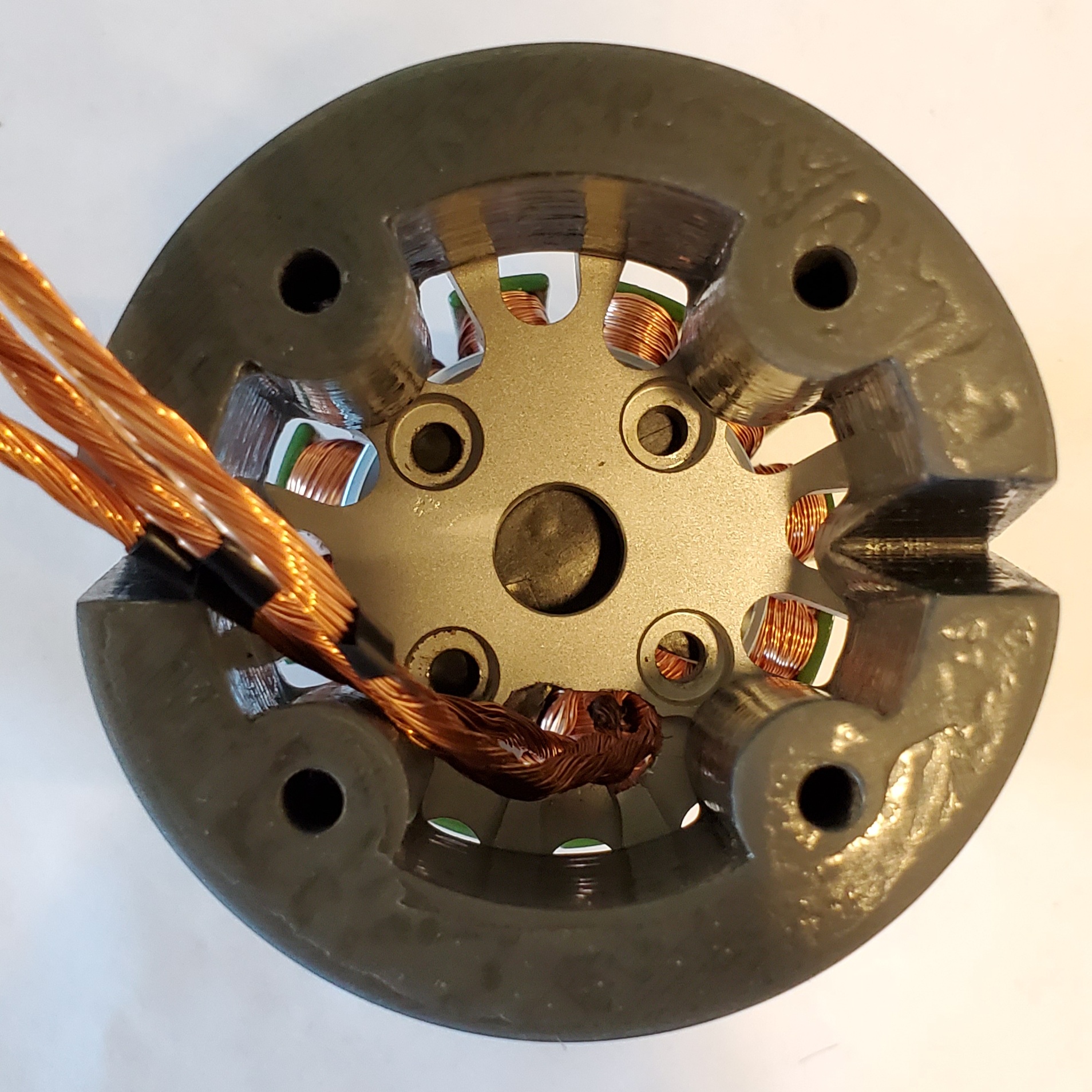
The machine shop at SCU is also helping me with this project. The shop used the CNC to spot face the inside and outside of the bottom face. The purpose of this is to improve thermal conductivity when mounting the VESC and heat sink with thermal adhesive. The original surface was tarnished and I was worried would cause thermal resistance.